US5875550A - Steer spindle bullet tool - Google Patents
Steer spindle bullet tool Download PDFInfo
- Publication number
- US5875550A US5875550A US08/899,229 US89922997A US5875550A US 5875550 A US5875550 A US 5875550A US 89922997 A US89922997 A US 89922997A US 5875550 A US5875550 A US 5875550A
- Authority
- US
- United States
- Prior art keywords
- spindle
- bullet
- steer
- diameter
- inches
- Prior art date
- Legal status (The legal status is an assumption and is not a legal conclusion. Google has not performed a legal analysis and makes no representation as to the accuracy of the status listed.)
- Expired - Lifetime
Links
- 239000000463 material Substances 0.000 claims description 8
- 125000000218 acetic acid group Chemical group C(C)(=O)* 0.000 claims description 3
- 125000006850 spacer group Chemical group 0.000 description 11
- 230000000712 assembly Effects 0.000 description 4
- 238000000429 assembly Methods 0.000 description 4
- 238000000034 method Methods 0.000 description 4
- 239000004677 Nylon Substances 0.000 description 3
- 238000004519 manufacturing process Methods 0.000 description 3
- 229920001778 nylon Polymers 0.000 description 3
- 239000004699 Ultra-high molecular weight polyethylene Substances 0.000 description 2
- 230000007246 mechanism Effects 0.000 description 2
- 229920000785 ultra high molecular weight polyethylene Polymers 0.000 description 2
- 229920004943 Delrin® Polymers 0.000 description 1
- 230000002411 adverse Effects 0.000 description 1
- 238000013459 approach Methods 0.000 description 1
- 230000000694 effects Effects 0.000 description 1
- 239000012530 fluid Substances 0.000 description 1
- 238000009434 installation Methods 0.000 description 1
- 238000003754 machining Methods 0.000 description 1
- 238000012986 modification Methods 0.000 description 1
- 230000004048 modification Effects 0.000 description 1
- 230000036316 preload Effects 0.000 description 1
- 239000011435 rock Substances 0.000 description 1
- 238000007493 shaping process Methods 0.000 description 1
Images


Classifications
-
- B—PERFORMING OPERATIONS; TRANSPORTING
- B25—HAND TOOLS; PORTABLE POWER-DRIVEN TOOLS; MANIPULATORS
- B25B—TOOLS OR BENCH DEVICES NOT OTHERWISE PROVIDED FOR, FOR FASTENING, CONNECTING, DISENGAGING OR HOLDING
- B25B27/00—Hand tools, specially adapted for fitting together or separating parts or objects whether or not involving some deformation, not otherwise provided for
- B25B27/0028—Tools for removing or installing seals
-
- B—PERFORMING OPERATIONS; TRANSPORTING
- B25—HAND TOOLS; PORTABLE POWER-DRIVEN TOOLS; MANIPULATORS
- B25B—TOOLS OR BENCH DEVICES NOT OTHERWISE PROVIDED FOR, FOR FASTENING, CONNECTING, DISENGAGING OR HOLDING
- B25B27/00—Hand tools, specially adapted for fitting together or separating parts or objects whether or not involving some deformation, not otherwise provided for
- B25B27/02—Hand tools, specially adapted for fitting together or separating parts or objects whether or not involving some deformation, not otherwise provided for for connecting objects by press fit or detaching same
-
- B—PERFORMING OPERATIONS; TRANSPORTING
- B60—VEHICLES IN GENERAL
- B60B—VEHICLE WHEELS; CASTORS; AXLES FOR WHEELS OR CASTORS; INCREASING WHEEL ADHESION
- B60B27/00—Hubs
- B60B27/02—Hubs adapted to be rotatably arranged on axle
-
- B—PERFORMING OPERATIONS; TRANSPORTING
- B60—VEHICLES IN GENERAL
- B60B—VEHICLE WHEELS; CASTORS; AXLES FOR WHEELS OR CASTORS; INCREASING WHEEL ADHESION
- B60B37/00—Wheel-axle combinations, e.g. wheel sets
- B60B37/10—Wheel-axle combinations, e.g. wheel sets the wheels being individually rotatable around the axles
-
- F—MECHANICAL ENGINEERING; LIGHTING; HEATING; WEAPONS; BLASTING
- F16—ENGINEERING ELEMENTS AND UNITS; GENERAL MEASURES FOR PRODUCING AND MAINTAINING EFFECTIVE FUNCTIONING OF MACHINES OR INSTALLATIONS; THERMAL INSULATION IN GENERAL
- F16C—SHAFTS; FLEXIBLE SHAFTS; ELEMENTS OR CRANKSHAFT MECHANISMS; ROTARY BODIES OTHER THAN GEARING ELEMENTS; BEARINGS
- F16C19/00—Bearings with rolling contact, for exclusively rotary movement
- F16C19/54—Systems consisting of a plurality of bearings with rolling friction
- F16C19/546—Systems with spaced apart rolling bearings including at least one angular contact bearing
- F16C19/547—Systems with spaced apart rolling bearings including at least one angular contact bearing with two angular contact rolling bearings
- F16C19/548—Systems with spaced apart rolling bearings including at least one angular contact bearing with two angular contact rolling bearings in O-arrangement
-
- F—MECHANICAL ENGINEERING; LIGHTING; HEATING; WEAPONS; BLASTING
- F16—ENGINEERING ELEMENTS AND UNITS; GENERAL MEASURES FOR PRODUCING AND MAINTAINING EFFECTIVE FUNCTIONING OF MACHINES OR INSTALLATIONS; THERMAL INSULATION IN GENERAL
- F16C—SHAFTS; FLEXIBLE SHAFTS; ELEMENTS OR CRANKSHAFT MECHANISMS; ROTARY BODIES OTHER THAN GEARING ELEMENTS; BEARINGS
- F16C25/00—Bearings for exclusively rotary movement adjustable for wear or play
- F16C25/06—Ball or roller bearings
-
- F—MECHANICAL ENGINEERING; LIGHTING; HEATING; WEAPONS; BLASTING
- F16—ENGINEERING ELEMENTS AND UNITS; GENERAL MEASURES FOR PRODUCING AND MAINTAINING EFFECTIVE FUNCTIONING OF MACHINES OR INSTALLATIONS; THERMAL INSULATION IN GENERAL
- F16C—SHAFTS; FLEXIBLE SHAFTS; ELEMENTS OR CRANKSHAFT MECHANISMS; ROTARY BODIES OTHER THAN GEARING ELEMENTS; BEARINGS
- F16C35/00—Rigid support of bearing units; Housings, e.g. caps, covers
- F16C35/04—Rigid support of bearing units; Housings, e.g. caps, covers in the case of ball or roller bearings
- F16C35/06—Mounting or dismounting of ball or roller bearings; Fixing them onto shaft or in housing
- F16C35/063—Fixing them on the shaft
-
- F—MECHANICAL ENGINEERING; LIGHTING; HEATING; WEAPONS; BLASTING
- F16—ENGINEERING ELEMENTS AND UNITS; GENERAL MEASURES FOR PRODUCING AND MAINTAINING EFFECTIVE FUNCTIONING OF MACHINES OR INSTALLATIONS; THERMAL INSULATION IN GENERAL
- F16C—SHAFTS; FLEXIBLE SHAFTS; ELEMENTS OR CRANKSHAFT MECHANISMS; ROTARY BODIES OTHER THAN GEARING ELEMENTS; BEARINGS
- F16C19/00—Bearings with rolling contact, for exclusively rotary movement
- F16C19/22—Bearings with rolling contact, for exclusively rotary movement with bearing rollers essentially of the same size in one or more circular rows, e.g. needle bearings
- F16C19/34—Bearings with rolling contact, for exclusively rotary movement with bearing rollers essentially of the same size in one or more circular rows, e.g. needle bearings for both radial and axial load
- F16C19/36—Bearings with rolling contact, for exclusively rotary movement with bearing rollers essentially of the same size in one or more circular rows, e.g. needle bearings for both radial and axial load with a single row of rollers
- F16C19/364—Bearings with rolling contact, for exclusively rotary movement with bearing rollers essentially of the same size in one or more circular rows, e.g. needle bearings for both radial and axial load with a single row of rollers with tapered rollers, i.e. rollers having essentially the shape of a truncated cone
-
- F—MECHANICAL ENGINEERING; LIGHTING; HEATING; WEAPONS; BLASTING
- F16—ENGINEERING ELEMENTS AND UNITS; GENERAL MEASURES FOR PRODUCING AND MAINTAINING EFFECTIVE FUNCTIONING OF MACHINES OR INSTALLATIONS; THERMAL INSULATION IN GENERAL
- F16C—SHAFTS; FLEXIBLE SHAFTS; ELEMENTS OR CRANKSHAFT MECHANISMS; ROTARY BODIES OTHER THAN GEARING ELEMENTS; BEARINGS
- F16C2226/00—Joining parts; Fastening; Assembling or mounting parts
- F16C2226/50—Positive connections
- F16C2226/60—Positive connections with threaded parts, e.g. bolt and nut connections
-
- F—MECHANICAL ENGINEERING; LIGHTING; HEATING; WEAPONS; BLASTING
- F16—ENGINEERING ELEMENTS AND UNITS; GENERAL MEASURES FOR PRODUCING AND MAINTAINING EFFECTIVE FUNCTIONING OF MACHINES OR INSTALLATIONS; THERMAL INSULATION IN GENERAL
- F16C—SHAFTS; FLEXIBLE SHAFTS; ELEMENTS OR CRANKSHAFT MECHANISMS; ROTARY BODIES OTHER THAN GEARING ELEMENTS; BEARINGS
- F16C2326/00—Articles relating to transporting
- F16C2326/01—Parts of vehicles in general
- F16C2326/02—Wheel hubs or castors
-
- Y—GENERAL TAGGING OF NEW TECHNOLOGICAL DEVELOPMENTS; GENERAL TAGGING OF CROSS-SECTIONAL TECHNOLOGIES SPANNING OVER SEVERAL SECTIONS OF THE IPC; TECHNICAL SUBJECTS COVERED BY FORMER USPC CROSS-REFERENCE ART COLLECTIONS [XRACs] AND DIGESTS
- Y10—TECHNICAL SUBJECTS COVERED BY FORMER USPC
- Y10T—TECHNICAL SUBJECTS COVERED BY FORMER US CLASSIFICATION
- Y10T29/00—Metal working
- Y10T29/49—Method of mechanical manufacture
- Y10T29/49636—Process for making bearing or component thereof
- Y10T29/49696—Mounting
Definitions
- the present invention relates to a steering axle assembly for a motor vehicle, and more particularly, relates to a steer spindle bullet tool used in the steering axle assembly for a vehicle.
- the steering system of a vehicle has a standard hub assembly and spindle.
- the spindle hub assembly includes a steer spindle, a hub, a seal, an inner bearing and an outer bearing.
- the inner and outer bearings have to be precisely placed on the spindle and within the hub unit in order for the seal to properly seal the hub unit.
- the assembly of the hub currently involves an operator aligning the hub with the spindle and then gently pushing the assembly on to the spindle end. If the hub is not completely centered about the spindle then the inner and outer bearings will not be properly seated and the only available solution to the inner bearing alignment problem is for the operator to rock, in a side to side motion, the hub until the inner bearing is properly seated. Even then it is not a certainty that the hub has been properly seated on the spindle of the steering column.
- axle bullet for assembling a drive axle and other such applications, however there has never been a device developed in assembling steer spindles and the associated hub in the steering assembly.
- the axle bullet is placed within the axle, then the rotor and other parts are slid around the axle bullet such that the rotor is properly seated on the end of the axle.
- One object of the present invention is to provide a steer spindle bullet.
- Another object of the present invention is to provide a device for protecting the threads and seal during hub mounting.
- Yet a further advantage of the present invention is to provide a device that will pilot the outer bearing to reduce inner bearing hang-up and misalignment during installation of the hub on the steer spindle.
- Yet a further object of the present invention is to reduce the occurrence of the seal being off-centered or disassembled.
- a further object of the present invention is to provide a device to use with non-traditional hub assemblies such that the device will align a spacer between the inner bearing and outer bearing.
- the steer spindle bullet includes a body member which has a reduced stepped diameter portion, and a cavity on the opposite end.
- the spindle bullet also includes a circular channel along the axis of the body member which extends between the cavity and the end of the spindle bullet.
- the cavity has a predetermined outside diameter and inside diameter.
- One advantage of the present invention is that the steer spindle bullet will protect the spindle threads and hub seal during hub mounting.
- a further advantage of the present invention is that the steer spindle bullet will correctly pilot the outer bearing onto the spindle in order to reduce inner bearing hang-up or misalignment.
- a further advantage of the present invention is that the steer spindle bullet will reduce the possibility of seal misalignment or disassembly within the steer spindle hub assembly.
- a farther advantage of the present invention is that with traditional and non-traditional hub assemblies the spacer between the bearings will be properly aligned using the steer spindle bullet.
- FIG. 1 shows a plan view of the present invention.
- FIG. 2 shows a standard hub assembly
- FIG. 3 shows a mounting hub under prior art conditions.
- FIG. 4 shows the components of the seal within the hub assembly.
- FIG. 4A shows the assembled seal of FIG. 4.
- FIG. 5 shows a seal assembly within the hub.
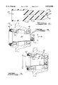
- FIG. 6 shows mounting the hub using the steer spindle bullet.
- FIG. 7 shows the hub mounted on the spindle using the steer spindle bullet.
- FIG. 8 shows a non-traditional hub assembly
- FIG. 9 shows mounting a non-traditional hub assembly under the prior art conditions.
- FIG. 10 shows mounting of a non-traditional hub assembly using the steer spindle bullet.
- FIG. 11 shows a non-traditional hub mounted on a spindle using the steer spindle bullet.
- the steer spindle bullet 16 generally includes a body member 18 that has a reduced diameter step portion 20.
- the reduced diameter portion 20 is used as a handle or grip member to place the steer spindle bullet 16 over a spindle 22 and to remove the steer spindle bullet 16 from the spindle 22 once the hub assembly 24 has been completed.
- the steer spindle bullet body 18 and handle 20 is made of delrin or acetyl which is similar to a nylon material.
- any other suitable nylon like material with the same hardness may also be used such as UHMW-PE (Ultra High Molecular Weight Poly Ethylene) or any other comparable material.
- the steer spindle bullet 16 is made by typical machining and/or any other method known which can shape the nylon like material into the required steer spindle bullet shape.
- the first reduced diameter portion 20 occurs at a gradual angle wherein the gradual step has an included angle of approximately 30° however, it should be noted that in general the included angle of the first reduced step down portion 26 can be anywhere from between 10° to 50° depending on the application necessary.
- the end of the handle 20 of the steer spindle bullet 16 includes a second reduced diameter portion 28 the angle at which the reduction occurs is also approximately 30° but it should be noted that any angle from 10° to approximately 60° may be used in shaping the end of the steer spindle bullet handle.
- the handle 20 in the preferred embodiment has a diameter of approximately 1.375 inches however, it should be noted that any appropriate diameter to fit the hand of the user and/or which is designed for specific use in the environment being used.
- the handle diameter can be within the range of one half an inch to several inches.
- the second reduced diameter portion 28 at the end of the handle has a diameter of approximately three quarters of an inch but it also should be noted that any other diameter may be used depending on the overall diameter of the handle such that it is smaller than the diameter of the handle.
- the handle portion has a length of approximately three inches, but it should be noted that any length greater than 1.25 inches may be used.
- the handle 20 of the body member 18 of the steer spindle bullet 16 is a large cylindrical shaped cavity 30 which is preferably bored out by an appropriate boring tool.
- the cylindrically shaped cavity 30 is used to place over the threads 32 of a spindle 34 of a steering axle.
- the body portion 18 of the steer spindle bullet 16 is approximately 2.25 inches long however it should be noted that depending on the size of the spindle this size may vary from a few inches to numerous inches.
- the cylindrical shaped cavity 30 has a diameter of approximately 1.5 inches plus or minus 0.005 of an inch however, it should be noted that generally speaking the diameter of the cavity will match the spindle thread diameter of the steer spindle being fitted with the hub and bearing assemblies.
- the tolerances are preferably 0.005 of an inch however it can be up to plus or minus five tenths of an inch.
- the depth of the cylindrical cavity is approximately 1.7 inches however, it should also be noted that depending on the size and shape of the spindle threads being covered the depth may vary from anywhere to a few inches to numerous inches.
- the outside diameter of the steer spindle bullet body member 18 is approximately 1.75 inches plus or minus 0.005 of an inch in its preferred embodiment however it should be noted that the outside diameter will vary with the diameter of the spindle journal 36. It should also be noted that the tolerances may be anywhere from 0.02 of an inch up to 0.0001 of an inch.
- a circular channel 38 extends the entire length of the steer spindle bullet 16 between the end of the handle 40 and the bottom of the cavity 30.
- the circular channel 38 has approximately a diameter of 0.125 inches and is placed along the axis of the steer spindle bullet 16. It should be noted that any other shape other than circular may be use for the channel and that the dimension of the channel may differ plus or minus two tenths of an inch depending on the needs of the steer spindle bullet 16 and the size of the spindle being protected.
- the circular channel 38 provides for a pressure release mechanism such that the steer spindle bullet 16 is easily placed upon the spindle thread and removed from the spindle threads without any back pressure or counter pressure adversely affecting the removability of the steer spindle bullet 16.
- the outside diameter of the body member of the steer spindle bullet 16 is machined to match the dimension of the outer bearing spindle journal 36 such that it creates a parallel intersection between the outer ring spindle journal and the outer circumference of the steer spindle bullet 16.
- a centered hub assembly 24 and spindle 34 used on a steer axle include a steer spindle 34, a hub 24, a seal 42, an inner bearing 44, and an outer bearing 46.
- the hub 24 is placed over the end of the spindle 34 and the seal 42 engages the spindle 34 and keeps fluid from leaking from the hub 24 outside onto the steer axle.
- the inner bearing 44 is placed against the spindle 34 as the outer bearing 46 is placed at the end of the spindle 34 above the spindle threads 32.
- To mount the hub assembly 24 onto the steer axle under prior art methods includes the following steps. First, the hub assembly 24 is supported with an overhead crane. Then the operator will align the hub 24 with the spindle 34 and gently move the hub assembly 24 onto the end of the spindle 34.
- the hub 24 will not center itself upon the spindle 34 correctly which in turn will wedge the inner bearing 44 in an improperly seated manner against the spindle 34.
- This condition occurs because of the lack of aligning mechanisms between the hub 24 and the spindle 34 and because the clearance between the inner bearing 44 and the spindle journal 36 is very small.
- the operator can remedy the wedged inner bearing by either rocking the hub in a gentle side by side motion and in turn walk the bearing on the spindle 34 however, this causes the seal to become cocked within the hub and leads to improper seal position within the spindle 34 and the hub 24, see FIG. 5.
- the other alternative for the operator is to remove the hub 24 and to try sliding the entire hub assembly 24 on the spindle journal once again in a more centered fashion.
- the seal 42 which is placed within the mounting hub 24 includes a main case 48 which incorporates a seal lip 50, a wear sleeve 52 and retainer ring 54 into a U-shaped seal.
- the design of this seal 42 is such that if the inner bearing 44 becomes wedged on the spindle 34 because it is off center, as the operator removes the hub off the spindle so as to realign the hub the inner bearing cone will come into contact with the wear seal of the seal thus pushing the retaining ring off of the seal which in turn will completely disassemble the seal further increasing manufacturing costs and time to properly seat the hub upon the spindle journal. Damage may also occur to the seal components thus requiring a new seal and/or components further increasing manufacturing costs.
- the mounting of the hub assembly 24 on the steer axle with the present invention steer spindle bullet 16 is done as follows. First, the steer spindle bullet 16 is placed over the steer axle such that the spindle threads 32 are completely covered and that the outer diameter of the steer spindle bullet 16 aligns in a parallel interface with the outer bearing spindle journal 36. Next, the operator will support the hub 24 with an overhead crane and then while securing the outer bearing 46 in the hub 24 will slide the hub assembly over the bullet 16, see FIGS. 6, 7. As the outside diameter of the spindle bullet 16 is exactly the same dimension as the spindle journal 36 the piloting or guiding of the outer bearing 46 begins before the inner bearing 44 comes into contact with the inner bearing journal further upon the spindle 34.
- a non-traditional hub assembly includes a hub 24, a seal 42, an inner bearing 44, a spacer 56 means, and an outer bearing 46.
- the spacer 56 is placed between the inner and outer bearings (44, 46) and is used to control the preload and any end play of the wheel end in the steer axle.
- To mount the non-traditional hub assembly the current method includes using an overhead crane and having the outer bearing 46 held in place by hand or a retainer where that retainer is used during assembly and is then removed after the hub is mounted on the spindle 34. When the outer bearing 46 is being held by the operator the spacers 56 are able to drop the hub 24 into the cavity between the inner bearing and the outer bearing.
- the steer spindle bullet 16 is used for mounting a non-traditional hub assembly using a spacer 56 the bullet 16 will pilot the outer bearing 46 to reduce the inner bearing hang up and/or misseating and it also protects the threads in the seal from damage by the spacer and also properly centers and aligns the spacer 56 onto the spindle 34 of the steer axle.
Landscapes
- Engineering & Computer Science (AREA)
- Mechanical Engineering (AREA)
- General Engineering & Computer Science (AREA)
- Rolling Contact Bearings (AREA)
Abstract
A spindle bullet for mounting a hub on a steer spindle of a steer axle. The spindle bullet includes a body member in contact with a reduced diameter portion. The body member includes a circular cavity. A circular channel connects an end of the reduced diameter portion and the cavity.
Description
1. Field of the Invention
The present invention relates to a steering axle assembly for a motor vehicle, and more particularly, relates to a steer spindle bullet tool used in the steering axle assembly for a vehicle.
2. Description of Related Art
The steering system of a vehicle has a standard hub assembly and spindle. The spindle hub assembly includes a steer spindle, a hub, a seal, an inner bearing and an outer bearing. During the actually assembly of the steering system the inner and outer bearings have to be precisely placed on the spindle and within the hub unit in order for the seal to properly seal the hub unit.
The assembly of the hub currently involves an operator aligning the hub with the spindle and then gently pushing the assembly on to the spindle end. If the hub is not completely centered about the spindle then the inner and outer bearings will not be properly seated and the only available solution to the inner bearing alignment problem is for the operator to rock, in a side to side motion, the hub until the inner bearing is properly seated. Even then it is not a certainty that the hub has been properly seated on the spindle of the steering column.
The prior art has shown the use of an axle bullet for assembling a drive axle and other such applications, however there has never been a device developed in assembling steer spindles and the associated hub in the steering assembly. The axle bullet is placed within the axle, then the rotor and other parts are slid around the axle bullet such that the rotor is properly seated on the end of the axle.
Therefore, there is a need in the art for a device to simplify and insure proper bearing seating for a steer spindle and hub assembly operation.
One object of the present invention is to provide a steer spindle bullet.
Another object of the present invention is to provide a device for protecting the threads and seal during hub mounting.
Yet a further advantage of the present invention is to provide a device that will pilot the outer bearing to reduce inner bearing hang-up and misalignment during installation of the hub on the steer spindle.
Yet a further object of the present invention is to reduce the occurrence of the seal being off-centered or disassembled.
A further object of the present invention is to provide a device to use with non-traditional hub assemblies such that the device will align a spacer between the inner bearing and outer bearing.
To achieve the foregoing objects the steer spindle bullet includes a body member which has a reduced stepped diameter portion, and a cavity on the opposite end. The spindle bullet also includes a circular channel along the axis of the body member which extends between the cavity and the end of the spindle bullet. The cavity has a predetermined outside diameter and inside diameter.
One advantage of the present invention is that the steer spindle bullet will protect the spindle threads and hub seal during hub mounting.
A further advantage of the present invention is that the steer spindle bullet will correctly pilot the outer bearing onto the spindle in order to reduce inner bearing hang-up or misalignment.
A further advantage of the present invention is that the steer spindle bullet will reduce the possibility of seal misalignment or disassembly within the steer spindle hub assembly.
A farther advantage of the present invention is that with traditional and non-traditional hub assemblies the spacer between the bearings will be properly aligned using the steer spindle bullet.
Other objects, features and advantages of the present invention will become apparent from the subsequent description and appended claims, taken in conjunction with the accompanying drawings.
FIG. 1 shows a plan view of the present invention.
FIG. 2 shows a standard hub assembly.
FIG. 3 shows a mounting hub under prior art conditions.
FIG. 4 shows the components of the seal within the hub assembly.
FIG. 4A shows the assembled seal of FIG. 4.
FIG. 5 shows a seal assembly within the hub.
FIG. 6 shows mounting the hub using the steer spindle bullet.
FIG. 7 shows the hub mounted on the spindle using the steer spindle bullet.
FIG. 8 shows a non-traditional hub assembly.
FIG. 9 shows mounting a non-traditional hub assembly under the prior art conditions.
FIG. 10 shows mounting of a non-traditional hub assembly using the steer spindle bullet.
FIG. 11 shows a non-traditional hub mounted on a spindle using the steer spindle bullet.
Referring to the drawings, a steer spindle bullet 16 according to the present invention is shown. The steer spindle bullet 16 generally includes a body member 18 that has a reduced diameter step portion 20. The reduced diameter portion 20 is used as a handle or grip member to place the steer spindle bullet 16 over a spindle 22 and to remove the steer spindle bullet 16 from the spindle 22 once the hub assembly 24 has been completed.
In the preferred embodiment the steer spindle bullet body 18 and handle 20 is made of delrin or acetyl which is similar to a nylon material. However, it should be noted that any other suitable nylon like material with the same hardness may also be used such as UHMW-PE (Ultra High Molecular Weight Poly Ethylene) or any other comparable material.
The steer spindle bullet 16 is made by typical machining and/or any other method known which can shape the nylon like material into the required steer spindle bullet shape. The first reduced diameter portion 20 occurs at a gradual angle wherein the gradual step has an included angle of approximately 30° however, it should be noted that in general the included angle of the first reduced step down portion 26 can be anywhere from between 10° to 50° depending on the application necessary. The end of the handle 20 of the steer spindle bullet 16 includes a second reduced diameter portion 28 the angle at which the reduction occurs is also approximately 30° but it should be noted that any angle from 10° to approximately 60° may be used in shaping the end of the steer spindle bullet handle. The handle 20 in the preferred embodiment has a diameter of approximately 1.375 inches however, it should be noted that any appropriate diameter to fit the hand of the user and/or which is designed for specific use in the environment being used. The handle diameter can be within the range of one half an inch to several inches. The second reduced diameter portion 28 at the end of the handle has a diameter of approximately three quarters of an inch but it also should be noted that any other diameter may be used depending on the overall diameter of the handle such that it is smaller than the diameter of the handle. In the preferred embodiment the handle portion has a length of approximately three inches, but it should be noted that any length greater than 1.25 inches may be used.
Opposite the handle 20 of the body member 18 of the steer spindle bullet 16 is a large cylindrical shaped cavity 30 which is preferably bored out by an appropriate boring tool. The cylindrically shaped cavity 30 is used to place over the threads 32 of a spindle 34 of a steering axle. In the preferred embodiment the body portion 18 of the steer spindle bullet 16 is approximately 2.25 inches long however it should be noted that depending on the size of the spindle this size may vary from a few inches to numerous inches. In the preferred embodiment the cylindrical shaped cavity 30 has a diameter of approximately 1.5 inches plus or minus 0.005 of an inch however, it should be noted that generally speaking the diameter of the cavity will match the spindle thread diameter of the steer spindle being fitted with the hub and bearing assemblies. However it should be mentioned that the tolerances are preferably 0.005 of an inch however it can be up to plus or minus five tenths of an inch. Also in the preferred embodiment the depth of the cylindrical cavity is approximately 1.7 inches however, it should also be noted that depending on the size and shape of the spindle threads being covered the depth may vary from anywhere to a few inches to numerous inches. The outside diameter of the steer spindle bullet body member 18 is approximately 1.75 inches plus or minus 0.005 of an inch in its preferred embodiment however it should be noted that the outside diameter will vary with the diameter of the spindle journal 36. It should also be noted that the tolerances may be anywhere from 0.02 of an inch up to 0.0001 of an inch.
A circular channel 38 extends the entire length of the steer spindle bullet 16 between the end of the handle 40 and the bottom of the cavity 30. The circular channel 38 has approximately a diameter of 0.125 inches and is placed along the axis of the steer spindle bullet 16. It should be noted that any other shape other than circular may be use for the channel and that the dimension of the channel may differ plus or minus two tenths of an inch depending on the needs of the steer spindle bullet 16 and the size of the spindle being protected. In operation the circular channel 38 provides for a pressure release mechanism such that the steer spindle bullet 16 is easily placed upon the spindle thread and removed from the spindle threads without any back pressure or counter pressure adversely affecting the removability of the steer spindle bullet 16. The outside diameter of the body member of the steer spindle bullet 16 is machined to match the dimension of the outer bearing spindle journal 36 such that it creates a parallel intersection between the outer ring spindle journal and the outer circumference of the steer spindle bullet 16.
In operation a centered hub assembly 24 and spindle 34 used on a steer axle include a steer spindle 34, a hub 24, a seal 42, an inner bearing 44, and an outer bearing 46. The hub 24 is placed over the end of the spindle 34 and the seal 42 engages the spindle 34 and keeps fluid from leaking from the hub 24 outside onto the steer axle. The inner bearing 44 is placed against the spindle 34 as the outer bearing 46 is placed at the end of the spindle 34 above the spindle threads 32. To mount the hub assembly 24 onto the steer axle under prior art methods includes the following steps. First, the hub assembly 24 is supported with an overhead crane. Then the operator will align the hub 24 with the spindle 34 and gently move the hub assembly 24 onto the end of the spindle 34. However, it is common that the hub 24 will not center itself upon the spindle 34 correctly which in turn will wedge the inner bearing 44 in an improperly seated manner against the spindle 34. This condition occurs because of the lack of aligning mechanisms between the hub 24 and the spindle 34 and because the clearance between the inner bearing 44 and the spindle journal 36 is very small. Currently, the operator can remedy the wedged inner bearing by either rocking the hub in a gentle side by side motion and in turn walk the bearing on the spindle 34 however, this causes the seal to become cocked within the hub and leads to improper seal position within the spindle 34 and the hub 24, see FIG. 5. The other alternative for the operator is to remove the hub 24 and to try sliding the entire hub assembly 24 on the spindle journal once again in a more centered fashion.
It has to be noted that the seal 42 which is placed within the mounting hub 24 includes a main case 48 which incorporates a seal lip 50, a wear sleeve 52 and retainer ring 54 into a U-shaped seal. The design of this seal 42 is such that if the inner bearing 44 becomes wedged on the spindle 34 because it is off center, as the operator removes the hub off the spindle so as to realign the hub the inner bearing cone will come into contact with the wear seal of the seal thus pushing the retaining ring off of the seal which in turn will completely disassemble the seal further increasing manufacturing costs and time to properly seat the hub upon the spindle journal. Damage may also occur to the seal components thus requiring a new seal and/or components further increasing manufacturing costs.
The mounting of the hub assembly 24 on the steer axle with the present invention steer spindle bullet 16 is done as follows. First, the steer spindle bullet 16 is placed over the steer axle such that the spindle threads 32 are completely covered and that the outer diameter of the steer spindle bullet 16 aligns in a parallel interface with the outer bearing spindle journal 36. Next, the operator will support the hub 24 with an overhead crane and then while securing the outer bearing 46 in the hub 24 will slide the hub assembly over the bullet 16, see FIGS. 6, 7. As the outside diameter of the spindle bullet 16 is exactly the same dimension as the spindle journal 36 the piloting or guiding of the outer bearing 46 begins before the inner bearing 44 comes into contact with the inner bearing journal further upon the spindle 34. This will in effect reduce the possibility of the inner bearing becoming cock-eyed or misseated and wedged on the spindle 34 because the alignment begins before the inner bearing 44 even approaches the spindle 34. This will allow for accurate centering of the hub assembly 24 upon the steer axle and reduce manufacturing cost because of seals that have to be replaced or bearing hub assemblies that had to be placed upon the spindle numerous times.
A non-traditional hub assembly includes a hub 24, a seal 42, an inner bearing 44, a spacer 56 means, and an outer bearing 46. The spacer 56 is placed between the inner and outer bearings (44, 46) and is used to control the preload and any end play of the wheel end in the steer axle. To mount the non-traditional hub assembly the current method includes using an overhead crane and having the outer bearing 46 held in place by hand or a retainer where that retainer is used during assembly and is then removed after the hub is mounted on the spindle 34. When the outer bearing 46 is being held by the operator the spacers 56 are able to drop the hub 24 into the cavity between the inner bearing and the outer bearing. As the operator slides the hub over the spindle the spacer has been known to come into contact with the spindle threads and possibly damage the threads or the spacer 56 and then the operator has to simultaneously align the spacer 56 with the spindle 34 while he is placing the hub onto the spindle. Another problem with the prior art method is that as the hub 24 is under the spindle there is the possibility and likely occurrence of the bearing becoming entangled with the journal on the spindle end of the axle. However, if the steer spindle bullet 16 is used for mounting a non-traditional hub assembly using a spacer 56 the bullet 16 will pilot the outer bearing 46 to reduce the inner bearing hang up and/or misseating and it also protects the threads in the seal from damage by the spacer and also properly centers and aligns the spacer 56 onto the spindle 34 of the steer axle.
The present invention has been described in an illustrative manner, it is to be understood that the terminology which has been used is intended to be in the nature of words of description rather than of limitation.
Many modifications and variations of the present invention are possible in light of the above teachings. Therefore, within the scope of the appended claims, the present invention may be practiced otherwise than as specifically described.
Claims (18)
1. A spindle bullet, said spindle bullet including:
a body member, said body member including a reduced diameter step portion, said body member having a cavity at an end;
a circular channel extending along the axis of the body member, said channel extends between said cavity and an end of said reduced diameter portion, said channel releases pressure for said spindle bullet, said cavity end having a predetermined outside diameter and a predetermined inside diameter.
2. The spindle bullet of claim 1 wherein said body is made of a plastic material.
3. The spindle bullet of claim 2 wherein said plastic material is acetyl.
4. The spindle bullet of claim 1 wherein said reduced diameter portion has a predetermined angle of incline.
5. The spindle bullet of claim 1 further including a second reduced diameter portion.
6. The spindle bullet of claim 1 wherein said spindle bullet has a length between 3 inches and 12 inches.
7. The spindle bullet of claim 1 wherein said outer diameter is between 0.5 inches and 4.125 inches.
8. The spindle bullet of claim 1 wherein said inside diameter is between 0.25 inch and 4 inches.
9. A spindle bullet for use in mounting a hub assembly on a steer spindle, the steer spindle having an outer bearing spindle journal and spindle threads, said spindle bullet including:
a body member made of a plastic material, said body member having a cylindrical cavity in one end thereof, said body member having a predetermined outside diameter, said cavity having a predetermined diameter and depth;
a reduced diameter handle joined by a fixed angle step to said body member, said handle having a predetermined diameter;
a second reduced diameter portion joined by a fixed angle step to said handle;
a circular channel along an axis of said spindle bullet, said channel extending from said cavity to said second reduced diameter portion.
10. The spindle bullet of claim 9 wherein said spindle bullet has a length of approximately 5.25 inches.
11. The spindle bullet of claim 9 wherein said outside diameter is approximately 1.75 inches.
12. The spindle bullet of claim 1 wherein said inside diameter is approximately 1.5 inches.
13. The spindle bullet of claim 9 wherein said plastic material is acetyl.
14. The spindle bullet of claim 9 wherein said fixed angle step is approximately 30°.
15. The spindle bullet of claim 9 wherein said outside diameter is approximately equal to an outer bearing spindle journal diameter.
16. The spindle bullet of claim 9 wherein said inside diameter is approximately equal to a diameter of steer spindle threads.
17. The spindle bullet of claim 9 wherein said spindle bullet guides bearings onto said spindle and said spindle bullet protects spindle threads.
18. The spindle bullet of claim 9 wherein said channel releases air from one end thereof to facilitate removal of said spindle bullet from the steer spindle.
Priority Applications (2)
| Application Number | Priority Date | Filing Date | Title |
|---|---|---|---|
| US08/899,229 US5875550A (en) | 1997-07-23 | 1997-07-23 | Steer spindle bullet tool |
| CA002235201A CA2235201A1 (en) | 1997-07-23 | 1998-04-20 | Steer spindle bullet tool |
Applications Claiming Priority (1)
| Application Number | Priority Date | Filing Date | Title |
|---|---|---|---|
| US08/899,229 US5875550A (en) | 1997-07-23 | 1997-07-23 | Steer spindle bullet tool |
Publications (1)
| Publication Number | Publication Date |
|---|---|
| US5875550A true US5875550A (en) | 1999-03-02 |
Family
ID=25410642
Family Applications (1)
| Application Number | Title | Priority Date | Filing Date |
|---|---|---|---|
| US08/899,229 Expired - Lifetime US5875550A (en) | 1997-07-23 | 1997-07-23 | Steer spindle bullet tool |
Country Status (2)
| Country | Link |
|---|---|
| US (1) | US5875550A (en) |
| CA (1) | CA2235201A1 (en) |
Cited By (14)
| Publication number | Priority date | Publication date | Assignee | Title |
|---|---|---|---|---|
| US6149244A (en) * | 1998-05-29 | 2000-11-21 | Consolidated Metco Inc. | Wheel hub assembly and method of installing a hub on an axle |
| US6533363B1 (en) * | 2002-02-26 | 2003-03-18 | Meritor Heavy Vehicle Technology, Llc | Grease retainer for vehicle wheel hubs |
| US6647606B2 (en) * | 1998-06-23 | 2003-11-18 | Nissan Motor Co., Ltd. | Jig and method for assembling toroidal continuously variable transmission |
| US20040117969A1 (en) * | 2001-03-06 | 2004-06-24 | Avery Michael C. | Installation of a hub/bearing assembly for an automotive vehicle |
| US20060137186A1 (en) * | 2003-02-07 | 2006-06-29 | Koyo Seiko Co., Ltd. | Method for assembling rolling bearing device |
| US20070086687A1 (en) * | 2003-10-14 | 2007-04-19 | Shevket Cengiz R | Asymmetric hub assembly |
| US20070271790A1 (en) * | 2006-05-25 | 2007-11-29 | Bingham Douglas S | Methods and guide members to transfer a wheel assembly |
| US20080230999A1 (en) * | 2007-03-20 | 2008-09-25 | Hopper Jeffrey N | Seal installation tool and method of using same |
| US20090005182A1 (en) * | 2007-06-27 | 2009-01-01 | Kyung Don Lee | Mounting structure of constant velocity joint and bearing |
| DE102009024988A1 (en) * | 2009-06-16 | 2010-12-30 | Aktiebolaget Skf | Bearing arrangement with at least two axially spaced bearings |
| FR3000986A1 (en) * | 2013-01-17 | 2014-07-18 | Peugeot Citroen Automobiles Sa | Method for assembling rotor of oil pump on crankshaft in engine of car, involves sliding rotary part with respect to longitudinal direction of conical element such that one or multiple portions of rotary part slide along conical element |
| US10054165B2 (en) * | 2015-01-15 | 2018-08-21 | Aktiebolaget Skf | Wheel bearing unit and method of securing the wheel bearing unit for transport |
| JP2018165524A (en) * | 2017-03-28 | 2018-10-25 | Nok株式会社 | Sealing device |
| US20230003302A1 (en) * | 2020-04-23 | 2023-01-05 | Nok Corporation | Gasket mounting structure |
Citations (15)
| Publication number | Priority date | Publication date | Assignee | Title |
|---|---|---|---|---|
| US3537163A (en) * | 1968-04-30 | 1970-11-03 | Robert H Steidl | Method of installing a cylindrical element into a cylindrical bore |
| US3824660A (en) * | 1973-05-04 | 1974-07-23 | Gen Tire & Rubber Co | Method and apparatus for vacuum assembling of bushings |
| US3981513A (en) * | 1975-05-27 | 1976-09-21 | Allis-Chalmers, Rumely, Ltd. | Steering axle assembly |
| US4150468A (en) * | 1975-11-03 | 1979-04-24 | The Timken Company | Adjusting process for bearings |
| US4338711A (en) * | 1980-10-09 | 1982-07-13 | Wright John T | Brake adjuster tool |
| US4660500A (en) * | 1985-03-23 | 1987-04-28 | Petri Ag | Steering wheel installation alignment device |
| US4832413A (en) * | 1987-03-17 | 1989-05-23 | Waggoner Wayne M | Device for mounting vehicle wheels |
| US4847989A (en) * | 1983-06-16 | 1989-07-18 | Burr Oak Tool & Gauge Company | Spiral expanding bullet |
| US4847971A (en) * | 1988-03-04 | 1989-07-18 | Gevas James C | Wheeled vehicle tire wheel mounting aid |
| US5165156A (en) * | 1990-05-29 | 1992-11-24 | Shultz William E | Clutch housing assembly and planetary gear assembly tool |
| US5184402A (en) * | 1990-09-05 | 1993-02-09 | Nippon Seiko Kabushiki Kaisha | Method of installing roller bearing |
| US5209623A (en) * | 1990-08-08 | 1993-05-11 | Krehnovi Michael E | Wheel stud installation apparatus |
| US5341559A (en) * | 1993-04-13 | 1994-08-30 | Fatigue Technology, Inc. | Method and apparatus for securing a tubular bushing in a circular opening |
| US5386630A (en) * | 1993-09-27 | 1995-02-07 | The Timken Company | Process and tool for adjusting bearings |
| US5757084A (en) * | 1995-09-15 | 1998-05-26 | Consolidated Metco, Inc. | Wheel hub assembly and method of installing a hub on an axle |
-
1997
- 1997-07-23 US US08/899,229 patent/US5875550A/en not_active Expired - Lifetime
-
1998
- 1998-04-20 CA CA002235201A patent/CA2235201A1/en not_active Abandoned
Patent Citations (15)
| Publication number | Priority date | Publication date | Assignee | Title |
|---|---|---|---|---|
| US3537163A (en) * | 1968-04-30 | 1970-11-03 | Robert H Steidl | Method of installing a cylindrical element into a cylindrical bore |
| US3824660A (en) * | 1973-05-04 | 1974-07-23 | Gen Tire & Rubber Co | Method and apparatus for vacuum assembling of bushings |
| US3981513A (en) * | 1975-05-27 | 1976-09-21 | Allis-Chalmers, Rumely, Ltd. | Steering axle assembly |
| US4150468A (en) * | 1975-11-03 | 1979-04-24 | The Timken Company | Adjusting process for bearings |
| US4338711A (en) * | 1980-10-09 | 1982-07-13 | Wright John T | Brake adjuster tool |
| US4847989A (en) * | 1983-06-16 | 1989-07-18 | Burr Oak Tool & Gauge Company | Spiral expanding bullet |
| US4660500A (en) * | 1985-03-23 | 1987-04-28 | Petri Ag | Steering wheel installation alignment device |
| US4832413A (en) * | 1987-03-17 | 1989-05-23 | Waggoner Wayne M | Device for mounting vehicle wheels |
| US4847971A (en) * | 1988-03-04 | 1989-07-18 | Gevas James C | Wheeled vehicle tire wheel mounting aid |
| US5165156A (en) * | 1990-05-29 | 1992-11-24 | Shultz William E | Clutch housing assembly and planetary gear assembly tool |
| US5209623A (en) * | 1990-08-08 | 1993-05-11 | Krehnovi Michael E | Wheel stud installation apparatus |
| US5184402A (en) * | 1990-09-05 | 1993-02-09 | Nippon Seiko Kabushiki Kaisha | Method of installing roller bearing |
| US5341559A (en) * | 1993-04-13 | 1994-08-30 | Fatigue Technology, Inc. | Method and apparatus for securing a tubular bushing in a circular opening |
| US5386630A (en) * | 1993-09-27 | 1995-02-07 | The Timken Company | Process and tool for adjusting bearings |
| US5757084A (en) * | 1995-09-15 | 1998-05-26 | Consolidated Metco, Inc. | Wheel hub assembly and method of installing a hub on an axle |
Cited By (22)
| Publication number | Priority date | Publication date | Assignee | Title |
|---|---|---|---|---|
| US6149244A (en) * | 1998-05-29 | 2000-11-21 | Consolidated Metco Inc. | Wheel hub assembly and method of installing a hub on an axle |
| US6647606B2 (en) * | 1998-06-23 | 2003-11-18 | Nissan Motor Co., Ltd. | Jig and method for assembling toroidal continuously variable transmission |
| US20040117969A1 (en) * | 2001-03-06 | 2004-06-24 | Avery Michael C. | Installation of a hub/bearing assembly for an automotive vehicle |
| US6935005B2 (en) * | 2001-03-06 | 2005-08-30 | The Timken Company | Installation of, a hub/bearing assembly for an automotive vehicle |
| US6533363B1 (en) * | 2002-02-26 | 2003-03-18 | Meritor Heavy Vehicle Technology, Llc | Grease retainer for vehicle wheel hubs |
| US7757402B2 (en) * | 2003-02-07 | 2010-07-20 | Jtekt Corporation | Method for assembling rolling bearing device |
| US20060137186A1 (en) * | 2003-02-07 | 2006-06-29 | Koyo Seiko Co., Ltd. | Method for assembling rolling bearing device |
| US20070086687A1 (en) * | 2003-10-14 | 2007-04-19 | Shevket Cengiz R | Asymmetric hub assembly |
| US20070271790A1 (en) * | 2006-05-25 | 2007-11-29 | Bingham Douglas S | Methods and guide members to transfer a wheel assembly |
| US7900357B2 (en) * | 2007-03-20 | 2011-03-08 | GM Global Technology Operations LLC | Seal installation tool and method of using same |
| US20080230999A1 (en) * | 2007-03-20 | 2008-09-25 | Hopper Jeffrey N | Seal installation tool and method of using same |
| US20090005182A1 (en) * | 2007-06-27 | 2009-01-01 | Kyung Don Lee | Mounting structure of constant velocity joint and bearing |
| US7841949B2 (en) * | 2007-06-27 | 2010-11-30 | Korea Flange Co., Ltd. | Mounting structure of constant velocity joint and bearing |
| DE102009024988A1 (en) * | 2009-06-16 | 2010-12-30 | Aktiebolaget Skf | Bearing arrangement with at least two axially spaced bearings |
| US20110033147A1 (en) * | 2009-06-16 | 2011-02-10 | Aktiebolaget Skf | Bearing Assembly |
| US8632255B2 (en) | 2009-06-16 | 2014-01-21 | Aktiebolaget Skf | Bearing assembly |
| DE102009024988B4 (en) * | 2009-06-16 | 2018-11-22 | Aktiebolaget Skf | Bearing arrangement with at least two axially spaced bearings |
| FR3000986A1 (en) * | 2013-01-17 | 2014-07-18 | Peugeot Citroen Automobiles Sa | Method for assembling rotor of oil pump on crankshaft in engine of car, involves sliding rotary part with respect to longitudinal direction of conical element such that one or multiple portions of rotary part slide along conical element |
| US10054165B2 (en) * | 2015-01-15 | 2018-08-21 | Aktiebolaget Skf | Wheel bearing unit and method of securing the wheel bearing unit for transport |
| JP2018165524A (en) * | 2017-03-28 | 2018-10-25 | Nok株式会社 | Sealing device |
| US20230003302A1 (en) * | 2020-04-23 | 2023-01-05 | Nok Corporation | Gasket mounting structure |
| US12117081B2 (en) * | 2020-04-23 | 2024-10-15 | Nok Corporation | Gasket mounting structure |
Also Published As
| Publication number | Publication date |
|---|---|
| CA2235201A1 (en) | 1999-01-23 |
Similar Documents
| Publication | Publication Date | Title |
|---|---|---|
| US5875550A (en) | Steer spindle bullet tool | |
| EP0997657B1 (en) | Adjustable preload spindle | |
| US5165169A (en) | Bearing servicing tool | |
| US11821463B2 (en) | Rotary machining device, method of manufacturing hub unit bearing and method of manufacturing vehicle | |
| JP4051102B2 (en) | Portable power polishing equipment | |
| US5074788A (en) | Device for preventing intrusion of foreign matter into dental handpiece | |
| US5150994A (en) | Spindle means of machine center | |
| US5651726A (en) | Mounting apparatus for grinding wheels | |
| EP1640090B1 (en) | Spindle unit of a machine tool | |
| US8714559B2 (en) | Spindle seal with tangential flow-inducing distribution ring | |
| US20060051005A1 (en) | Pivot bearing with lubricant transmission | |
| JP4593150B2 (en) | Universal joint | |
| JP3862488B2 (en) | Processing method and apparatus for hub wheel in wheel bearing device | |
| JPH1090103A (en) | Automatic locking device for wheel of automobile in balancing machine | |
| CN101736452A (en) | Thrust bearing | |
| US5709074A (en) | Open end spinning roller with exchangeable combing ring | |
| US20090155011A1 (en) | Rotary tapered tool holder with adapter sleeve | |
| KR100611360B1 (en) | Shaping pulley assembly for belt notching machine | |
| US20020090885A1 (en) | Flange connection | |
| US4930261A (en) | Valve resurfacing apparatus and method for making the same | |
| MXPA04012782A (en) | Staked spindle nut system. | |
| US5802900A (en) | Apparatus for fabricating a fluid bearing | |
| JPH10263902A (en) | Spindle device | |
| JPH07204908A (en) | Spindle device | |
| JPS624550A (en) | Tool holder unit with oiler |
Legal Events
| Date | Code | Title | Description |
|---|---|---|---|
| AS | Assignment |
Owner name: FREUDENBERG-NOK GENERAL PARTNERSHIP, MICHIGAN Free format text: ASSIGNMENT OF ASSIGNORS INTEREST;ASSIGNOR:KOHN, DAN;REEL/FRAME:008667/0442 Effective date: 19970723 |
|
| STCF | Information on status: patent grant |
Free format text: PATENTED CASE |
|
| FPAY | Fee payment |
Year of fee payment: 4 |
|
| REMI | Maintenance fee reminder mailed | ||
| FPAY | Fee payment |
Year of fee payment: 8 |
|
| SULP | Surcharge for late payment |
Year of fee payment: 7 |
|
| FPAY | Fee payment |
Year of fee payment: 12 |