US5873654A - Twin screw extruder type batch mixers - Google Patents
Twin screw extruder type batch mixers Download PDFInfo
- Publication number
- US5873654A US5873654A US08/744,633 US74463396A US5873654A US 5873654 A US5873654 A US 5873654A US 74463396 A US74463396 A US 74463396A US 5873654 A US5873654 A US 5873654A
- Authority
- US
- United States
- Prior art keywords
- screws
- mixer
- screw
- outlet
- clockwise
- Prior art date
- Legal status (The legal status is an assumption and is not a legal conclusion. Google has not performed a legal analysis and makes no representation as to the accuracy of the status listed.)
- Expired - Fee Related
Links
- 239000000463 material Substances 0.000 claims abstract description 34
- 238000002156 mixing Methods 0.000 claims abstract description 16
- 238000007599 discharging Methods 0.000 claims abstract description 7
- 238000002844 melting Methods 0.000 claims description 4
- 230000008018 melting Effects 0.000 claims description 4
- 239000011295 pitch Substances 0.000 claims description 3
- 238000001125 extrusion Methods 0.000 description 9
- 238000013461 design Methods 0.000 description 5
- 238000000034 method Methods 0.000 description 5
- 238000012360 testing method Methods 0.000 description 4
- 229920001971 elastomer Polymers 0.000 description 2
- 230000010006 flight Effects 0.000 description 2
- 239000013529 heat transfer fluid Substances 0.000 description 2
- 238000012986 modification Methods 0.000 description 2
- 230000004048 modification Effects 0.000 description 2
- 229920000642 polymer Polymers 0.000 description 2
- 239000002861 polymer material Substances 0.000 description 2
- 238000005070 sampling Methods 0.000 description 2
- 229910000831 Steel Inorganic materials 0.000 description 1
- 239000000654 additive Substances 0.000 description 1
- 239000000956 alloy Substances 0.000 description 1
- 229910045601 alloy Inorganic materials 0.000 description 1
- 238000006243 chemical reaction Methods 0.000 description 1
- 238000004140 cleaning Methods 0.000 description 1
- 238000013329 compounding Methods 0.000 description 1
- 238000010924 continuous production Methods 0.000 description 1
- 239000000806 elastomer Substances 0.000 description 1
- 238000005516 engineering process Methods 0.000 description 1
- 239000008187 granular material Substances 0.000 description 1
- 230000005484 gravity Effects 0.000 description 1
- 239000011346 highly viscous material Substances 0.000 description 1
- 239000011261 inert gas Substances 0.000 description 1
- 238000004898 kneading Methods 0.000 description 1
- 239000007788 liquid Substances 0.000 description 1
- 238000005259 measurement Methods 0.000 description 1
- 239000004033 plastic Substances 0.000 description 1
- 229920003023 plastic Polymers 0.000 description 1
- 238000012545 processing Methods 0.000 description 1
- 230000003134 recirculating effect Effects 0.000 description 1
- 230000002441 reversible effect Effects 0.000 description 1
- 238000013341 scale-up Methods 0.000 description 1
- 238000007493 shaping process Methods 0.000 description 1
- 239000007787 solid Substances 0.000 description 1
- 239000010959 steel Substances 0.000 description 1
- 229920001169 thermoplastic Polymers 0.000 description 1
- 229920001187 thermosetting polymer Polymers 0.000 description 1
- 239000004416 thermosoftening plastic Substances 0.000 description 1
- 238000012546 transfer Methods 0.000 description 1
Images

Classifications
-
- B—PERFORMING OPERATIONS; TRANSPORTING
- B29—WORKING OF PLASTICS; WORKING OF SUBSTANCES IN A PLASTIC STATE IN GENERAL
- B29B—PREPARATION OR PRETREATMENT OF THE MATERIAL TO BE SHAPED; MAKING GRANULES OR PREFORMS; RECOVERY OF PLASTICS OR OTHER CONSTITUENTS OF WASTE MATERIAL CONTAINING PLASTICS
- B29B7/00—Mixing; Kneading
- B29B7/30—Mixing; Kneading continuous, with mechanical mixing or kneading devices
- B29B7/34—Mixing; Kneading continuous, with mechanical mixing or kneading devices with movable mixing or kneading devices
- B29B7/38—Mixing; Kneading continuous, with mechanical mixing or kneading devices with movable mixing or kneading devices rotary
- B29B7/46—Mixing; Kneading continuous, with mechanical mixing or kneading devices with movable mixing or kneading devices rotary with more than one shaft
- B29B7/48—Mixing; Kneading continuous, with mechanical mixing or kneading devices with movable mixing or kneading devices rotary with more than one shaft with intermeshing devices, e.g. screws
-
- B—PERFORMING OPERATIONS; TRANSPORTING
- B29—WORKING OF PLASTICS; WORKING OF SUBSTANCES IN A PLASTIC STATE IN GENERAL
- B29B—PREPARATION OR PRETREATMENT OF THE MATERIAL TO BE SHAPED; MAKING GRANULES OR PREFORMS; RECOVERY OF PLASTICS OR OTHER CONSTITUENTS OF WASTE MATERIAL CONTAINING PLASTICS
- B29B7/00—Mixing; Kneading
- B29B7/02—Mixing; Kneading non-continuous, with mechanical mixing or kneading devices, i.e. batch type
- B29B7/06—Mixing; Kneading non-continuous, with mechanical mixing or kneading devices, i.e. batch type with movable mixing or kneading devices
- B29B7/10—Mixing; Kneading non-continuous, with mechanical mixing or kneading devices, i.e. batch type with movable mixing or kneading devices rotary
- B29B7/12—Mixing; Kneading non-continuous, with mechanical mixing or kneading devices, i.e. batch type with movable mixing or kneading devices rotary with single shaft
- B29B7/14—Mixing; Kneading non-continuous, with mechanical mixing or kneading devices, i.e. batch type with movable mixing or kneading devices rotary with single shaft with screw or helix
-
- B—PERFORMING OPERATIONS; TRANSPORTING
- B29—WORKING OF PLASTICS; WORKING OF SUBSTANCES IN A PLASTIC STATE IN GENERAL
- B29B—PREPARATION OR PRETREATMENT OF THE MATERIAL TO BE SHAPED; MAKING GRANULES OR PREFORMS; RECOVERY OF PLASTICS OR OTHER CONSTITUENTS OF WASTE MATERIAL CONTAINING PLASTICS
- B29B7/00—Mixing; Kneading
- B29B7/02—Mixing; Kneading non-continuous, with mechanical mixing or kneading devices, i.e. batch type
- B29B7/06—Mixing; Kneading non-continuous, with mechanical mixing or kneading devices, i.e. batch type with movable mixing or kneading devices
- B29B7/10—Mixing; Kneading non-continuous, with mechanical mixing or kneading devices, i.e. batch type with movable mixing or kneading devices rotary
- B29B7/18—Mixing; Kneading non-continuous, with mechanical mixing or kneading devices, i.e. batch type with movable mixing or kneading devices rotary with more than one shaft
-
- B—PERFORMING OPERATIONS; TRANSPORTING
- B29—WORKING OF PLASTICS; WORKING OF SUBSTANCES IN A PLASTIC STATE IN GENERAL
- B29B—PREPARATION OR PRETREATMENT OF THE MATERIAL TO BE SHAPED; MAKING GRANULES OR PREFORMS; RECOVERY OF PLASTICS OR OTHER CONSTITUENTS OF WASTE MATERIAL CONTAINING PLASTICS
- B29B7/00—Mixing; Kneading
- B29B7/80—Component parts, details or accessories; Auxiliary operations
- B29B7/82—Heating or cooling
- B29B7/826—Apparatus therefor
-
- B—PERFORMING OPERATIONS; TRANSPORTING
- B29—WORKING OF PLASTICS; WORKING OF SUBSTANCES IN A PLASTIC STATE IN GENERAL
- B29C—SHAPING OR JOINING OF PLASTICS; SHAPING OF MATERIAL IN A PLASTIC STATE, NOT OTHERWISE PROVIDED FOR; AFTER-TREATMENT OF THE SHAPED PRODUCTS, e.g. REPAIRING
- B29C48/00—Extrusion moulding, i.e. expressing the moulding material through a die or nozzle which imparts the desired form; Apparatus therefor
- B29C48/25—Component parts, details or accessories; Auxiliary operations
- B29C48/36—Means for plasticising or homogenising the moulding material or forcing it through the nozzle or die
- B29C48/395—Means for plasticising or homogenising the moulding material or forcing it through the nozzle or die using screws surrounded by a cooperating barrel, e.g. single screw extruders
- B29C48/40—Means for plasticising or homogenising the moulding material or forcing it through the nozzle or die using screws surrounded by a cooperating barrel, e.g. single screw extruders using two or more parallel screws or at least two parallel non-intermeshing screws, e.g. twin screw extruders
- B29C48/405—Intermeshing co-rotating screws
-
- B—PERFORMING OPERATIONS; TRANSPORTING
- B29—WORKING OF PLASTICS; WORKING OF SUBSTANCES IN A PLASTIC STATE IN GENERAL
- B29C—SHAPING OR JOINING OF PLASTICS; SHAPING OF MATERIAL IN A PLASTIC STATE, NOT OTHERWISE PROVIDED FOR; AFTER-TREATMENT OF THE SHAPED PRODUCTS, e.g. REPAIRING
- B29C48/00—Extrusion moulding, i.e. expressing the moulding material through a die or nozzle which imparts the desired form; Apparatus therefor
- B29C48/25—Component parts, details or accessories; Auxiliary operations
- B29C48/78—Thermal treatment of the extrusion moulding material or of preformed parts or layers, e.g. by heating or cooling
- B29C48/80—Thermal treatment of the extrusion moulding material or of preformed parts or layers, e.g. by heating or cooling at the plasticising zone, e.g. by heating cylinders
- B29C48/83—Heating or cooling the cylinders
-
- B—PERFORMING OPERATIONS; TRANSPORTING
- B29—WORKING OF PLASTICS; WORKING OF SUBSTANCES IN A PLASTIC STATE IN GENERAL
- B29C—SHAPING OR JOINING OF PLASTICS; SHAPING OF MATERIAL IN A PLASTIC STATE, NOT OTHERWISE PROVIDED FOR; AFTER-TREATMENT OF THE SHAPED PRODUCTS, e.g. REPAIRING
- B29C48/00—Extrusion moulding, i.e. expressing the moulding material through a die or nozzle which imparts the desired form; Apparatus therefor
- B29C48/25—Component parts, details or accessories; Auxiliary operations
- B29C48/92—Measuring, controlling or regulating
-
- B—PERFORMING OPERATIONS; TRANSPORTING
- B29—WORKING OF PLASTICS; WORKING OF SUBSTANCES IN A PLASTIC STATE IN GENERAL
- B29C—SHAPING OR JOINING OF PLASTICS; SHAPING OF MATERIAL IN A PLASTIC STATE, NOT OTHERWISE PROVIDED FOR; AFTER-TREATMENT OF THE SHAPED PRODUCTS, e.g. REPAIRING
- B29C2948/00—Indexing scheme relating to extrusion moulding
- B29C2948/92—Measuring, controlling or regulating
- B29C2948/92009—Measured parameter
- B29C2948/92019—Pressure
-
- B—PERFORMING OPERATIONS; TRANSPORTING
- B29—WORKING OF PLASTICS; WORKING OF SUBSTANCES IN A PLASTIC STATE IN GENERAL
- B29C—SHAPING OR JOINING OF PLASTICS; SHAPING OF MATERIAL IN A PLASTIC STATE, NOT OTHERWISE PROVIDED FOR; AFTER-TREATMENT OF THE SHAPED PRODUCTS, e.g. REPAIRING
- B29C2948/00—Indexing scheme relating to extrusion moulding
- B29C2948/92—Measuring, controlling or regulating
- B29C2948/92009—Measured parameter
- B29C2948/92209—Temperature
Definitions
- This invention relates to batch mixers with twin screw configurations.
- the mixers are useful for melting, mixing and reacting highly viscous materials. Especially, they are useful for melting, mixing and reacting polymer materials.
- Another shortcoming with a internal mixer is in tts use in evaluating materials for an extrusion process.
- One of the major uses of a laboratory internal mixer is to test the processibility of thermoplastics, thermosets and elastomers, and transfer the information to a continuous production process such as extrusion.
- both the geometry of a internal mixer and mixing mechanism are different from those of an extruder, it is often difficult to predict extrusion results from information learnt through a batch internal mixer study.
- Scott and Macosko (Scott, C. E. and Macosko, C. W., Polymer Engineering and Science, 33, 1065, 1993) developed a batch mixer named the recirculating screw mixer(RSM) based on single screw extrusion technology.
- the mixing mechanism in RSM is more representative of that in a continuous single screw extruder and thus results obtained are more meaningful in scale up for continuous single screw extrusion operation.
- a single screw extruder and RSM do not have very good mixing capabilities. More polymer mixing and reaction processes are performed in twin screw extruders which have much better mixing capabilities.
- a twin screw type batch mixer should provide not only a good batch mixer but also a tool with which useful information which can be easily transformed to continuous twin screw extrusion can be learnt.
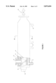
- FIG. 1 is an elevation view of the same hand screw flight version of the batch mixer of the present invention
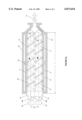
- FIGS. 2a-2b are cross sectional plan views of FIG. 1.
- FIG. 2a shows the screw rotational directions and material flow during the charging and discharging mode
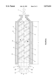
- FIG. 2b shows the screw rotational directions and material flow during the mixing mode.
- FIG. 3 is a cross sectional end view taken along line A--A of FIG. 1;
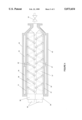
- FIG. 4 is a cross sectional plan view of an opposite hand screw flight version of the mixer of the present invention.
- a barrel casing or housing 11 is made of a suitable material such as an alloy of steel.
- Housing 11 is shown in a FIG. 8 shape, but is not limited to such a shape. Housing 11 also need not be limited to one piece as shown in FIGS. 1 to 3. It may consist of different sections of different lengths or same length. Each section may be formed of two halves(as known as split barrel design).
- Housing 11 contains a feed inlet 12 and a product outlet with a closing device 13, as well as a jacket chamber 14 having an outer shell 20 for use with an appropriate heat transfer fluid.
- Heat transfer fluid inlet and outlet conduits 15 communicate with jacket chamber 14 which may also contain other typical auxiliaries such as thermocouples, pressure gauges, sampling ports, etc. which are not shown.
- Screws 16 and 17 runs in two modes: co-rotating and counter-rotating.
- Co-rotating mode is normally used just for loading or unloading materials while counter-rotating mode is normally used for testing, mixing, reacting materials.
- Screw shaft ends 19a and 19b extend through shaft seals 18a and 18b are coupled to reversible motors 22 and 23.
- a torque measurement attachment which measures the torque on the screws is used but not shown in the figures.
- the helix angles and the channel depths of both screws need not be same.
- the rotational speeds of the screws also need not be same.
- the Screw flights 26 and 27 of screw 16 and 17 can be either right handed or left handed, but must be of the same hand.
- the diameters of screw 16 and screw 17 are indicated as D a and D b and the mixer length is indicated as L.
- the distance between the two screw center lines 24 and 25 is shown as B.
- the pitches of the screws may independently ranges from 1/5 to 8 of screw diameter as is well known in the art of extrusion.
- the mixer length to half of the sum of two screw diameters should be in the range of 1 to 40.
- FIG. 4 The apparatus shown in FIG. 4 is analogous to that shown in FIGS. 1-3, except that the two screw flights are of opposite hands. Another exception is that for opposite hand screw flight case, there are two configurations: Staggered or matched screw flight oppositions. In the opposite hand screw flight apparatus, counter-rotating mode is normally for loading and unloading materials while the co-rotating mode is normally for testing, mixing and reacting materials.
- the discharge can be connected to a die and thus the material can be discharged into a certain form such as strands and then be cut into granules.
- the apparatus may be equipped with ports for liquid or solid additives, devolatilization, pressure release, sampling, viewing, etc.
- the mixers may be equipped with temperature and/or pressure gauges, thermocouples, inert gas blanket lines, dies at the discharge zone, etc.
Landscapes
- Engineering & Computer Science (AREA)
- Mechanical Engineering (AREA)
- Physics & Mathematics (AREA)
- Thermal Sciences (AREA)
- Processing And Handling Of Plastics And Other Materials For Molding In General (AREA)
Abstract
A twin screw extruder type batch mixer that is comprised of two screws parallel to each other with the distance between the two screw center lines being larger or equal than the half of the sum of two screw diameters and the two screws conveying material in the opposite direction during mixing and reacting stage and the same direction during charging and discharging stages; and a barrel casing completely enclosing said screws which can run clockwise and counter-clockwise independently.
Description
This is a provisional application Ser. No. 60/006,280 filed Nov. 7, 1996.
This invention relates to batch mixers with twin screw configurations. The mixers are useful for melting, mixing and reacting highly viscous materials. Especially, they are useful for melting, mixing and reacting polymer materials.
The most widely used batch mixer for bulk polymer materials mixing is rotor type mixer called internal mixer which was originally designed by Banbury (Banbury, F. H., U.S. Pat. No. 1,200,070, 1916). Over the years since its inception, numerous modifications in design have been introduced, but the basic principle remains the same. They are all comprised of two parallel kneading rotors, each rotating within the corresponding region of a double trough or W-shaped chamber, but with the walls of the chamber continuing upwards over the rotors to constitute a closed mixing chamber. Although widely used in rubber and plastics compounding, these types of mixers have some shortcomings. One of them is material discharge. In these machines, at the completion of the mixing cycle, the discharge door is opened and the mass was discharged by gravity as shapeless lump or lumps which are difficult to handle for the next operation. This discharge mechanism makes it necessary to interpose at least one more intermediate processing stage before final shaping or next operation. It is also difficult for some materials to discharge and discharge completely. For small laboratory internal mixer machines as produced by C. W. Brabender Inc. and Haake Buchler Instruments Inc., there is no discharge door. The discharge has to be performed by disassembling the mixer and then removing the material manually. Very often, time spent on recovering the final material and cleaning the machine is more than testing time.
Another shortcoming with a internal mixer is in tts use in evaluating materials for an extrusion process. One of the major uses of a laboratory internal mixer is to test the processibility of thermoplastics, thermosets and elastomers, and transfer the information to a continuous production process such as extrusion. As both the geometry of a internal mixer and mixing mechanism are different from those of an extruder, it is often difficult to predict extrusion results from information learnt through a batch internal mixer study. Scott and Macosko (Scott, C. E. and Macosko, C. W., Polymer Engineering and Science, 33, 1065, 1993) developed a batch mixer named the recirculating screw mixer(RSM) based on single screw extrusion technology. The mixing mechanism in RSM is more representative of that in a continuous single screw extruder and thus results obtained are more meaningful in scale up for continuous single screw extrusion operation. However, a single screw extruder and RSM do not have very good mixing capabilities. More polymer mixing and reaction processes are performed in twin screw extruders which have much better mixing capabilities. Thus a twin screw type batch mixer should provide not only a good batch mixer but also a tool with which useful information which can be easily transformed to continuous twin screw extrusion can be learnt.
Thus, it is the objective of this invention:
(a) to provide a design of a batch mixer with a twin screw configuration;
(b) to provide a design of a batch mixer which has a efficient material discharge mechanism and the material can be formed into certain shape per discharge;
(c) to provide a design of a batch mixer which can be used to provide useful information for continuous twin screw extrusion processes.
FIG. 1 is an elevation view of the same hand screw flight version of the batch mixer of the present invention;
FIGS. 2a-2b are cross sectional plan views of FIG. 1. FIG. 2a shows the screw rotational directions and material flow during the charging and discharging mode; FIG. 2b shows the screw rotational directions and material flow during the mixing mode.
FIG. 3 is a cross sectional end view taken along line A--A of FIG. 1;
FIG. 4 is a cross sectional plan view of an opposite hand screw flight version of the mixer of the present invention.
In the apparatus of FIGS. 1 TO 3, a barrel casing or housing 11 is made of a suitable material such as an alloy of steel. Housing 11 is shown in a FIG. 8 shape, but is not limited to such a shape. Housing 11 also need not be limited to one piece as shown in FIGS. 1 to 3. It may consist of different sections of different lengths or same length. Each section may be formed of two halves(as known as split barrel design). Housing 11 contains a feed inlet 12 and a product outlet with a closing device 13, as well as a jacket chamber 14 having an outer shell 20 for use with an appropriate heat transfer fluid. Heat transfer fluid inlet and outlet conduits 15 communicate with jacket chamber 14 which may also contain other typical auxiliaries such as thermocouples, pressure gauges, sampling ports, etc. which are not shown. Screws 16 and 17 runs in two modes: co-rotating and counter-rotating. Co-rotating mode is normally used just for loading or unloading materials while counter-rotating mode is normally used for testing, mixing, reacting materials. Screw shaft ends 19a and 19b extend through shaft seals 18a and 18b are coupled to reversible motors 22 and 23. A torque measurement attachment which measures the torque on the screws is used but not shown in the figures. The helix angles and the channel depths of both screws need not be same. The rotational speeds of the screws also need not be same. The Screw flights 26 and 27 of screw 16 and 17 can be either right handed or left handed, but must be of the same hand. The diameters of screw 16 and screw 17 are indicated as Da and Db and the mixer length is indicated as L. The distance between the two screw center lines 24 and 25 is shown as B. The pitches of the screws may independently ranges from 1/5 to 8 of screw diameter as is well known in the art of extrusion. The mixer length to half of the sum of two screw diameters should be in the range of 1 to 40.
The apparatus shown in FIG. 4 is analogous to that shown in FIGS. 1-3, except that the two screw flights are of opposite hands. Another exception is that for opposite hand screw flight case, there are two configurations: Staggered or matched screw flight oppositions. In the opposite hand screw flight apparatus, counter-rotating mode is normally for loading and unloading materials while the co-rotating mode is normally for testing, mixing and reacting materials.
From the description above, a number of advantages of the twin screw type batch mixer become evident:
(a) During the charging and discharging stages, both of the screws drag material toward the discharge, which makes the process very easy.
(b) The discharge can be connected to a die and thus the material can be discharged into a certain form such as strands and then be cut into granules.
(c) As the material in this type of mixer experiences similar history as in a twin screw extruder, the information learnt from the batch mixer can be readily transfered to a continuous twin screw extrusion process.
Although several specific configurations of the mixers of the present invention have been shown for illustrative purposes, it should be understood that modifications well known in the art pertaining to extruders and batch mixers may be made to the present invention without departing from the spirit thereof. For example, the apparatus may be equipped with ports for liquid or solid additives, devolatilization, pressure release, sampling, viewing, etc. In addition, the mixers may be equipped with temperature and/or pressure gauges, thermocouples, inert gas blanket lines, dies at the discharge zone, etc. The scope of the invention should be determined not by the embodiments illustrated, but by the appended claims which follow.
Claims (6)
1. A twin screw extruder type batch mixer comprised of:
(a) two screws parallel to each other and non-intermeshing;
(b) a barrel casing completely enclosing said screws and containing a feed inlet and a product outlet with a closing device on each, said screws having same hands throughout the entire mixer barrel casing.
(c) means for charging materials to the mixer by running the two screws in the same direction either clockwise or counter-clockwise so that the material flows from the inlet to the outlet direction;
(d) means for melting and mixing the material by running the two screws in the opposite directions so that one screw move the material from the inlet to the outlet direction while the other screw moves the material from outlet to the inlet direction;
(e) means for discharging the mixed material by running the two screws in the same direction either clockwise or counter-clockwise so that the material flows from the inlet to the outlet direction;
(f) means for forming the discharging material into certain shapes connected to said mixer outlet.
2. The mixer of claim 1 wherein the screws independently have pitches in the range of 1/5 to 8 of screw diameter.
3. The mixer of claim 1 wherein the mixer length to half of the sum of two screw diameters ratio is in the range of 1 to 40.
4. A twin screw extruder type batch mixer comprised of:
(a) two screws parallel to each other and non-intermeshing;
(b) a barrel casing completely enclosing said screws and containing a feed inlet and a product outlet with a closing device on each, said screws having opposite hands throughout the entire mixer barrel casing.
(c) means for charging materials to the mixer by running the two screws in the opposite directions either clockwise or counter-clockwise so that the material flows from the inlet to the outlet direction;
(d) means for melting and mixing the material by running the two screws in the same direction so that one screw move the material from the inlet to the outlet direction while the other screw moves the material from outlet to the inlet direction;
(e) means for discharging the mixed material by running the two screws in the opposite direction either clockwise or counter-clockwise so that the material flows from the inlet to the outlet direction;
(f) means for forming the discharging material into certain shapes connected to said mixer outlet.
5. The mixer of claim 4 wherein the screws independently have pitches in the range of 1/5 to 8 of screw diameter.
6. The mixer of claim 5 wherein the mixer length to half of the sum of two screw diameters ratio is in the range of 1 to 40.
Priority Applications (1)
| Application Number | Priority Date | Filing Date | Title |
|---|---|---|---|
| US08/744,633 US5873654A (en) | 1995-11-07 | 1996-11-06 | Twin screw extruder type batch mixers |
Applications Claiming Priority (2)
| Application Number | Priority Date | Filing Date | Title |
|---|---|---|---|
| US628095P | 1995-11-07 | 1995-11-07 | |
| US08/744,633 US5873654A (en) | 1995-11-07 | 1996-11-06 | Twin screw extruder type batch mixers |
Publications (1)
| Publication Number | Publication Date |
|---|---|
| US5873654A true US5873654A (en) | 1999-02-23 |
Family
ID=26675425
Family Applications (1)
| Application Number | Title | Priority Date | Filing Date |
|---|---|---|---|
| US08/744,633 Expired - Fee Related US5873654A (en) | 1995-11-07 | 1996-11-06 | Twin screw extruder type batch mixers |
Country Status (1)
| Country | Link |
|---|---|
| US (1) | US5873654A (en) |
Cited By (10)
| Publication number | Priority date | Publication date | Assignee | Title |
|---|---|---|---|---|
| US20030124211A1 (en) * | 2001-02-15 | 2003-07-03 | Avraam Isayev | Ultrasound assisted continuous process for making polymer blends and copolymers |
| US20050069601A1 (en) * | 2001-12-07 | 2005-03-31 | Reinhard Uphus | Multiple extruder configuration |
| US20050270894A1 (en) * | 2004-06-04 | 2005-12-08 | Gates Thomas A | Dynamic mixer screw tip |
| US20060061007A1 (en) * | 1999-12-15 | 2006-03-23 | Hong Chen | Method and apparatus for extruding cementitious articles |
| US20060193197A1 (en) * | 2003-01-27 | 2006-08-31 | Pierre-Alain Fleury | Method for the continuous phase conversion of a product |
| US20070109911A1 (en) * | 2005-11-16 | 2007-05-17 | Neubauer Anthony C | High speed and direct driven rotating equipment for polyolefin manufacturing |
| US20090008220A1 (en) * | 2005-07-04 | 2009-01-08 | Basf Aktiengessellschaft | Use of an Apparatus for Adding at Least One Additive to a Reactor Interior |
| US20120097048A1 (en) * | 2009-09-02 | 2012-04-26 | Stefano Tomatis | Curd kneading apparatus for production of pasta-filata cheese |
| DE102011054409A1 (en) * | 2011-10-12 | 2013-04-18 | Noris Plastic GmbH & Co. KG | Extruder device i.e. twin screw extruder device, for use in plastic industry for manufacturing plastic composites, has worm gears comprising drives, where distance between gears is large such that gears are not combed with one another |
| CN103962035A (en) * | 2013-02-04 | 2014-08-06 | 昆山尚达智机械有限公司 | Novel double-helix blender |
Citations (5)
| Publication number | Priority date | Publication date | Assignee | Title |
|---|---|---|---|---|
| US3602484A (en) * | 1967-12-28 | 1971-08-31 | Poncet Pierre | Mixers |
| US3749374A (en) * | 1970-12-10 | 1973-07-31 | Werener & Pfleiderer | Screw extruder for the treatment of pulverized material |
| US4844619A (en) * | 1987-04-13 | 1989-07-04 | Weiler & Co. | Sampling mechanism for a meat mixing machine |
| US5083506A (en) * | 1991-03-06 | 1992-01-28 | Blentech Corporation | Continuous compartmented mixer |
| US5228775A (en) * | 1989-05-04 | 1993-07-20 | Blentech Corporation | Reversing blender agitators |
-
1996
- 1996-11-06 US US08/744,633 patent/US5873654A/en not_active Expired - Fee Related
Patent Citations (5)
| Publication number | Priority date | Publication date | Assignee | Title |
|---|---|---|---|---|
| US3602484A (en) * | 1967-12-28 | 1971-08-31 | Poncet Pierre | Mixers |
| US3749374A (en) * | 1970-12-10 | 1973-07-31 | Werener & Pfleiderer | Screw extruder for the treatment of pulverized material |
| US4844619A (en) * | 1987-04-13 | 1989-07-04 | Weiler & Co. | Sampling mechanism for a meat mixing machine |
| US5228775A (en) * | 1989-05-04 | 1993-07-20 | Blentech Corporation | Reversing blender agitators |
| US5083506A (en) * | 1991-03-06 | 1992-01-28 | Blentech Corporation | Continuous compartmented mixer |
Cited By (18)
| Publication number | Priority date | Publication date | Assignee | Title |
|---|---|---|---|---|
| US20060061007A1 (en) * | 1999-12-15 | 2006-03-23 | Hong Chen | Method and apparatus for extruding cementitious articles |
| US20030124211A1 (en) * | 2001-02-15 | 2003-07-03 | Avraam Isayev | Ultrasound assisted continuous process for making polymer blends and copolymers |
| US20050069601A1 (en) * | 2001-12-07 | 2005-03-31 | Reinhard Uphus | Multiple extruder configuration |
| US7017732B2 (en) * | 2001-12-07 | 2006-03-28 | Berstorff Gmbh | Multiple extruder configuration |
| US20060193197A1 (en) * | 2003-01-27 | 2006-08-31 | Pierre-Alain Fleury | Method for the continuous phase conversion of a product |
| US7762712B2 (en) * | 2003-01-27 | 2010-07-27 | List Holding Ag | Method for the continuous phase conversion of a product |
| US20050270894A1 (en) * | 2004-06-04 | 2005-12-08 | Gates Thomas A | Dynamic mixer screw tip |
| US7246936B2 (en) | 2004-06-04 | 2007-07-24 | Certainteed Corp. | Dynamic mixer screw tip |
| US20090008220A1 (en) * | 2005-07-04 | 2009-01-08 | Basf Aktiengessellschaft | Use of an Apparatus for Adding at Least One Additive to a Reactor Interior |
| US8206027B2 (en) * | 2005-07-04 | 2012-06-26 | Basf Aktiengesellschaft | Use of an apparatus for adding at least one additive to a reactor interior |
| US8790003B2 (en) | 2005-07-04 | 2014-07-29 | Basf Se | Use of an apparatus for adding at least one additive to a receptor interior |
| US20070109911A1 (en) * | 2005-11-16 | 2007-05-17 | Neubauer Anthony C | High speed and direct driven rotating equipment for polyolefin manufacturing |
| US20110085408A1 (en) * | 2005-11-16 | 2011-04-14 | Univation Technologies, Llc | High Speed and Direct Driven Rotating Equipment for Polyolefin Manufacturing |
| US8066423B2 (en) | 2005-11-16 | 2011-11-29 | Univation Technologies, Llc | High speed and direct driven rotating equipment for polyolefin manufacturing |
| US20120097048A1 (en) * | 2009-09-02 | 2012-04-26 | Stefano Tomatis | Curd kneading apparatus for production of pasta-filata cheese |
| DE102011054409A1 (en) * | 2011-10-12 | 2013-04-18 | Noris Plastic GmbH & Co. KG | Extruder device i.e. twin screw extruder device, for use in plastic industry for manufacturing plastic composites, has worm gears comprising drives, where distance between gears is large such that gears are not combed with one another |
| DE102011054409B4 (en) * | 2011-10-12 | 2021-02-11 | Noris Plastic GmbH & Co. KG | Extruder device and extrusion process, in particular for compounding plastics |
| CN103962035A (en) * | 2013-02-04 | 2014-08-06 | 昆山尚达智机械有限公司 | Novel double-helix blender |
Similar Documents
| Publication | Publication Date | Title |
|---|---|---|
| US5873654A (en) | Twin screw extruder type batch mixers | |
| JP4024976B2 (en) | Closed kneader | |
| Altomare et al. | An analysis of residence time distribution patterns in a twin screw cooking extruder | |
| US4059232A (en) | Stirring or agitating mills | |
| US3154808A (en) | Continuous internal stiff-gel mixer | |
| RU2550175C9 (en) | Auger elements for extrusion of viscoelastic compounds, application and process | |
| US3102716A (en) | Apparatus for mixing | |
| US5421650A (en) | Mixing machinery of the transfermix type | |
| US20040141405A1 (en) | Homogenizing and/or dispersing device comprising endless screws | |
| US3239878A (en) | Continuous internal stiff-gel mixer | |
| US3841814A (en) | Apparatus for processing plastic materials | |
| JPH0130615B2 (en) | ||
| JP2648513B2 (en) | Mixing machine and how to operate it | |
| US3700374A (en) | Continuous mixer with screw discharge control | |
| JPS6256086B2 (en) | ||
| US3623703A (en) | Machine for mixing and plasticating of plastics, rubber and other highly viscous materials at controlled pressure, friction and shear conditions | |
| US3998439A (en) | Apparatus for mixing materials in molding machines | |
| US3575382A (en) | Multipurpose continuous mixing and/or kneading apparatus | |
| US3730663A (en) | Pelletizer | |
| KR100311120B1 (en) | Recruiter for handling media | |
| JPS63258627A (en) | Kneading control method for kneading extruder | |
| US6224251B1 (en) | Continuous kneading machine | |
| CA1302398C (en) | High shear mixing | |
| GB1585531A (en) | Mixing apparatus | |
| US3676035A (en) | Apparatus for processing plastic materials |
Legal Events
| Date | Code | Title | Description |
|---|---|---|---|
| REMI | Maintenance fee reminder mailed | ||
| LAPS | Lapse for failure to pay maintenance fees | ||
| STCH | Information on status: patent discontinuation |
Free format text: PATENT EXPIRED DUE TO NONPAYMENT OF MAINTENANCE FEES UNDER 37 CFR 1.362 |
|
| FP | Lapsed due to failure to pay maintenance fee |
Effective date: 20030223 |