US587145A - eckert - Google Patents
eckert Download PDFInfo
- Publication number
- US587145A US587145A US587145DA US587145A US 587145 A US587145 A US 587145A US 587145D A US587145D A US 587145DA US 587145 A US587145 A US 587145A
- Authority
- US
- United States
- Prior art keywords
- semaphore
- lever
- actuating
- signal
- attachment
- Prior art date
- Legal status (The legal status is an assumption and is not a legal conclusion. Google has not performed a legal analysis and makes no representation as to the accuracy of the status listed.)
- Expired - Lifetime
Links
- ORILYTVJVMAKLC-UHFFFAOYSA-N Adamantane Natural products C1C(C2)CC3CC1CC2C3 ORILYTVJVMAKLC-UHFFFAOYSA-N 0.000 description 1
- 241001155961 Baris Species 0.000 description 1
- 238000010276 construction Methods 0.000 description 1
Images

Classifications
-
- B—PERFORMING OPERATIONS; TRANSPORTING
- B61—RAILWAYS
- B61L—GUIDING RAILWAY TRAFFIC; ENSURING THE SAFETY OF RAILWAY TRAFFIC
- B61L19/00—Arrangements for interlocking between points and signals by means of a single interlocking device, e.g. central control
- B61L19/02—Interlocking devices having mechanical or fluid-pressure operation
Definitions
- This invention relates to an improved com- IO pensating attachment for semaphore-signals in which the wire cords that connect the semaphores with the actuating-levers are kept perfectly taut at any temperature, so that the slackening of the wires and the consequent l 5 unreliable setting of the semaphore-signals is entirely prevented, and the absolute setting of the same at any temperature to the danger position, even when the connecting wires or cords should break, is secured; and the invention consists of a compensating attachment for semaphore-signals in which the wire cords that operate the semaphore-signal are passed over suitable pulleys applied to the f ulcrumed operating-lever and connected to a compen- .2 5 Eating device that takes up the slack of the wire cords and produces the setting to the danger position in case of the breaking of the connecting wire cord.
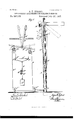
- Figure 1 represents a side elevation of my improved 5 compensating attachment for semaphore-signals, showing the same respectively in normal or dangerposition and in clear position in dotted lines.
- Fig. 2 is a like elevation showing the signal and its actuating-lever in re- 0 versed position, indicating that the track is clear.
- A represents a 4 5 semaphore-mast which is located at any suitable distance from the switchtower from which the semaphore-signal is set in the danger or clear position.
- B is the semaphore-signal, th at is pivotedin a suitable manner at a point near the upper end of the mast and is provided with a suitable counterweight.
- the fulcrumed and weighted lever C is connected by wire cords wit-h the actuating-lever D, which is located at the switch-tower, said wire cords being known as front and back Wires and are attached to the lever O equidistantly from the fulcrum, as shown in Fig. 1.
- the front wire E is guided over pulleys e e c and the back wire E over pulleys f f the ends of both wires being connected with a suitable compensating attachment G.
- the pulleys e and f are suspended by means of pivot links or hangers e and f from the lower portion D of the fulcrumed actuating- 7o lever D, said hangers being arranged equidistantly from the fulcrum on opposite sides of a the same.
- Each actuating-lever D is provided with the usual locking device d, by which the lever is locked in normal or danger position and clear position in connection with the block D as shown in Fig. 1.
- the compensating attachment is composed of a vertical rod g, which is guided in suitable eyes or sleeves 9', attached to a horizon- 8o tal plank G.
- the lower end of the vertical rod g is provided with a suitable weight G suspended thereto, while the upper end of the rod is provided with two arms, of which the right-hand arm is provided with a short hook, 8 5 while the left-hand arm is provided with a longer hook, as shown clearly in the drawings.
- the hook-shaped ends of the arms serve for engaging a horizontal bar 9 which is provided at one end with a downwardly- 9o bent portion g and at the opposite end with an upwardly-bent portion g and a hookshaped end g
- the ends of the front and back Wires are provided with rings, which are attached, respectively, to the right-hand end of the bar 9 and to the bent portion 9 of the same, while the hook-shaped ends of the forked vertical rod 9 are hung, respectively,
- the semaphore-signal B When the actuatinglever D is in its normal position, the semaphore-signal B is in its horizontal or danger position, so as to indicate that the track is not clear. hen the actuating-lever D is set into its second or clear position, the semaphore-signal is moved in its lower position and indicates thereby that the track is clear and that trains can pass.
- the weighted compensating attachment keeps the front and back wires that form con nections between the actuating-lever and semaphore-signal taut and takes up any slack that is caused by a change of temperature, and especially during hot weather when the connecting-wires are elongated by the influence of the heat.
- the compensating attachment has an additional advantagenamely, that it sets the semaphore-signal to danger in case of a break in the front or back wire.
- This position is illustrated in Fig. 2, in which it is assumed that the back wire is broken.
- the horizontal bar of the compensating attachment is disengaged and dropped down, so as to unhook the front wire,'leaving it slack, so that the counterweight on the semaphorepole places the semaphore-signal into the danger position and causing thereby the stoppage of any approaching train in case the track is not clear.
- a compensating attachment for semaphore-signals composed of a vertical rod, a weight applied to the lower end of same, arms at the upper end of same provided with hookshaped ends, and a disengaging-bar provided with bent portions and hook-shaped ends engaging respeetively the hooks of the arms of the vertical rod, and rings at the ends of the connecting semaphore-operating wires, substantially as set forth.
Landscapes
- Engineering & Computer Science (AREA)
- Mechanical Engineering (AREA)
- Orthopedics, Nursing, And Contraception (AREA)
Description
(No Model.) 2 Sheets-Sheet 1 A. E. EOKERT. GQMPENSATING ATTACHMENT FOR SEMAPHORE SIGNALS. No. 587,145. Patented July 27,1897.
lT/VESSE (No Model.) 2 Sheets-Sheet 2.
I A. E. EOKERT.
GOMPENSATING ATTACHMENT FOR SEMAPHORE SIGNALS.
No. 587,145. Patented July 27, 1897.
Ln; W 2722/ UNITED STATES PATENT nricn.
ADAM E. EGKERT, OF YONKERS, NEW YORK, ASSIGNOR OF ONE-HALF TO ALBERT H. FANGBONER, OF SAME PLACE.
COMPENSATING ATTACHMENT FOR SEMAPHORE-SIGNALS.
SPECIFICATIOLT forming part of Letters Patent No. 587,145, dated July 27, 1897.
Application filed May 7, 1897. Serial No. 635,474. (No modeli) To all whom it may concern.-
I Be it known that I, ADAM E. ECKERT, a citizen of the United States, residing at Yonkers, county of Westchester, State of New York,
have invented certain new and useful Improvements in Compensating Attachments for Semaphore-Signals, of which the following is a specification.
This invention relates to an improved com- IO pensating attachment for semaphore-signals in which the wire cords that connect the semaphores with the actuating-levers are kept perfectly taut at any temperature, so that the slackening of the wires and the consequent l 5 unreliable setting of the semaphore-signals is entirely prevented, and the absolute setting of the same at any temperature to the danger position, even when the connecting wires or cords should break, is secured; and the invention consists of a compensating attachment for semaphore-signals in which the wire cords that operate the semaphore-signal are passed over suitable pulleys applied to the f ulcrumed operating-lever and connected to a compen- .2 5 Eating device that takes up the slack of the wire cords and produces the setting to the danger position in case of the breaking of the connecting wire cord.
This invention consists, further, of the 0 special construction of the compensating attachment, as will be fully described hereinafter and finally pointed out in the claims.
In the accompanying drawings, Figure 1 represents a side elevation of my improved 5 compensating attachment for semaphore-signals, showing the same respectively in normal or dangerposition and in clear position in dotted lines. Fig. 2 is a like elevation showing the signal and its actuating-lever in re- 0 versed position, indicating that the track is clear.
Similar lettersof reference indicate corresponding parts.
Referring to the drawings, A represents a 4 5 semaphore-mast which is located at any suitable distance from the switchtower from which the semaphore-signal is set in the danger or clear position.
B is the semaphore-signal, th at is pivotedin a suitable manner at a point near the upper end of the mast and is provided with a suitable counterweight.
C is a weighted and fulcrnmed lever that is fulcrumed to the mast A at some distance below the signal-arm B and which is connected by apivot-rod G with the shorter arm of the semaphore-signal B. The fulcrumed and weighted lever C is connected by wire cords wit-h the actuating-lever D, which is located at the switch-tower, said wire cords being known as front and back Wires and are attached to the lever O equidistantly from the fulcrum, as shown in Fig. 1. The front wire E is guided over pulleys e e c and the back wire E over pulleys f f the ends of both wires being connected with a suitable compensating attachment G. The pulleys e and f are suspended by means of pivot links or hangers e and f from the lower portion D of the fulcrumed actuating- 7o lever D, said hangers being arranged equidistantly from the fulcrum on opposite sides of a the same. Each actuating-lever D is provided with the usual locking device d, by which the lever is locked in normal or danger position and clear position in connection with the block D as shown in Fig. 1. I
The compensating attachment is composed of a vertical rod g, which is guided in suitable eyes or sleeves 9', attached to a horizon- 8o tal plank G. The lower end of the vertical rod g is provided with a suitable weight G suspended thereto, while the upper end of the rod is provided with two arms, of which the right-hand arm is provided with a short hook, 8 5 while the left-hand arm is provided with a longer hook, as shown clearly in the drawings. The hook-shaped ends of the arms serve for engaging a horizontal bar 9 which is provided at one end with a downwardly- 9o bent portion g and at the opposite end with an upwardly-bent portion g and a hookshaped end g The ends of the front and back Wires are provided with rings, which are attached, respectively, to the right-hand end of the bar 9 and to the bent portion 9 of the same, while the hook-shaped ends of the forked vertical rod 9 are hung, respectively,
to the bent portion 9 and the hook-shaped end 9 of the bar When the actuatinglever D is in its normal position, the semaphore-signal B is in its horizontal or danger position, so as to indicate that the track is not clear. hen the actuating-lever D is set into its second or clear position, the semaphore-signal is moved in its lower position and indicates thereby that the track is clear and that trains can pass. Throughout the working of the semaphore-signal the weighted compensating attachment keeps the front and back wires that form con nections between the actuating-lever and semaphore-signal taut and takes up any slack that is caused by a change of temperature, and especially during hot weather when the connecting-wires are elongated by the influence of the heat.
The compensating attachment has an additional advantagenamely, that it sets the semaphore-signal to danger in case of a break in the front or back wire. This position is illustrated in Fig. 2, in which it is assumed that the back wire is broken. In this case the horizontal bar of the compensating attachment is disengaged and dropped down, so as to unhook the front wire,'leaving it slack, so that the counterweight on the semaphorepole places the semaphore-signal into the danger position and causing thereby the stoppage of any approaching train in case the track is not clear. If the front wire should break, the disengaging baris not unhooked, but the additional weight of the compensating attachment is applied to the weighted semaphore-actuatinglever, so that the signal is kept in its danger position, as shown in Fig. 2. In this manner semaphore-signals are reliably operated in connection with the compensating attachment, which is applied to the lower part of each actuating-lever, so that by acomparatively simple arrangement the reliable setting of semaphore-signals at all temperatures or in case of the breakage of the connectingwires is secured.
Having thus described my invention, I
claim as new and desire to secure by Letters Patent 1. The combination with a semaphore-sig- 11211, of a weighted balance-lever connected with the same, an actuating-lever for the same, guide-pulleys suspended from the lower part of the actuating-lever, front and back wires passing over the guide-pulleys of the actuating-lever and connected with the said weighted balance-lever, and a weighted compensating attachment operated by the breaking of either front or back wire, substantially as set forth.
2. The combination, with a semaphore-signal, of a weighted balance-lever connected with the same, an actuating-lever located in the semaphore-switch tower, guide-pulleys suspended from the lower part of the actuating-lever, connecting front and back wires passing over suitable guide-pulleys, and the pulleys on the actuating-lever, and a compensating attachment composed of a verticallyguided weighted rod having forked and hookshaped upper ends and a disengaging-bar the hook-shaped ends of which are connected with the ends of the said front and back wires and with the hook-shaped ends of said weighted rod, substantially as set forth.
3. A compensating attachment for semaphore-signals, composed of a vertical rod, a weight applied to the lower end of same, arms at the upper end of same provided with hookshaped ends, and a disengaging-bar provided with bent portions and hook-shaped ends engaging respeetively the hooks of the arms of the vertical rod, and rings at the ends of the connecting semaphore-operating wires, substantially as set forth.
In testimony that I claim the foregoing as my hwention I have signed my name in presence of two subscribing witnesses.
ADAM E. ECKER'I.
\Vitnesses:
PAUL GoEPEL, A. II'. FANGBONER.
Publications (1)
| Publication Number | Publication Date |
|---|---|
| US587145A true US587145A (en) | 1897-07-27 |
Family
ID=2655814
Family Applications (1)
| Application Number | Title | Priority Date | Filing Date |
|---|---|---|---|
| US587145D Expired - Lifetime US587145A (en) | eckert |
Country Status (1)
| Country | Link |
|---|---|
| US (1) | US587145A (en) |
-
0
- US US587145D patent/US587145A/en not_active Expired - Lifetime
Similar Documents
| Publication | Publication Date | Title |
|---|---|---|
| US498570A (en) | Suspension device for electric lamps | |
| US533128A (en) | Railroad-signal | |
| US638210A (en) | Compensator. | |
| US1192028A (en) | Skylight supporting and adjusting apparatus. | |
| US513934A (en) | Railroad-signal | |
| US533042A (en) | J jllpwgas | |
| US586587A (en) | Compensating device for wires | |
| US272122A (en) | Signal apparatus | |
| US535921A (en) | Wire-compensator | |
| US410754A (en) | Etienne ghirardi | |
| US521885A (en) | Compensator for signal-operating wires | |
| US617507A (en) | Railroad-signal | |
| US773098A (en) | Railway-signal. | |
| US506106A (en) | John fisher | |
| US306641A (en) | piper | |
| US296640A (en) | Car-coupling | |
| US805679A (en) | Gate. | |
| US611149A (en) | renton | |
| US551660A (en) | Signal | |
| US1239206A (en) | Brake-beam hanger. | |
| US1066409A (en) | Stop mechanism for locomotives. | |
| US567716A (en) | Signal-operating device | |
| US174979A (en) | Improvement in electric signaling attachments to railroad-cars | |
| US492526A (en) | brodie | |
| US780483A (en) | Railway signaling device. |