US587081A - Telephone-exchange apparatus - Google Patents
Telephone-exchange apparatus Download PDFInfo
- Publication number
- US587081A US587081A US587081DA US587081A US 587081 A US587081 A US 587081A US 587081D A US587081D A US 587081DA US 587081 A US587081 A US 587081A
- Authority
- US
- United States
- Prior art keywords
- line
- cells
- ground
- station
- lines
- Prior art date
- Legal status (The legal status is an assumption and is not a legal conclusion. Google has not performed a legal analysis and makes no representation as to the accuracy of the status listed.)
- Expired - Lifetime
Links
Images
Classifications
-
- B—PERFORMING OPERATIONS; TRANSPORTING
- B29—WORKING OF PLASTICS; WORKING OF SUBSTANCES IN A PLASTIC STATE IN GENERAL
- B29C—SHAPING OR JOINING OF PLASTICS; SHAPING OF MATERIAL IN A PLASTIC STATE, NOT OTHERWISE PROVIDED FOR; AFTER-TREATMENT OF THE SHAPED PRODUCTS, e.g. REPAIRING
- B29C48/00—Extrusion moulding, i.e. expressing the moulding material through a die or nozzle which imparts the desired form; Apparatus therefor
- B29C48/03—Extrusion moulding, i.e. expressing the moulding material through a die or nozzle which imparts the desired form; Apparatus therefor characterised by the shape of the extruded material at extrusion
Definitions
- FRANK R MOBERTY, OFDO VVNERS GROVE, ILLINOIS ASSIGNOR TO THE WESTERN ELECTRIC COMPANY, OF CHICAGO, ILLINOIS. y
- My invention concerns the operation of telephone-lines grouped intelephone-exchanges and provided with earth returns or with ground branches.
- the invention consists in the application to such line-circuits of polarization or counter electromotive force cells in the circuits in such a way as to prevent the creation in them of currents arising from differences of potential at the different ground connections. It involves also certain groupings of the lines, whereby the greatest freedom from extraneous currents may be attained with the least apparatus.
- the device which has been termed the polarization or counter-electromotive-force cell is well known to those skilled in electrical science. It may be an uniformed Plant storage-cell or any other pair of plates immersed in an electrolyte and adapted to become quickly polarized to oppose the passage through them of current in either direction.
- My invention consists in interposing in the ground branches of the lines liable to such currents a number of polarization-cells suflicient to counteract any difference of potential acting upon the line and thus to prevent the creation in thecircuit of any appreciable current from the electromotive force in the earth.
- these cells may be included in the ground branches of each line;
- the apparatus at the central station is also of usual character-a terminal spring-jack k and an annunciator l, responsive to signalingcurrent from the substation-generators, being' provided in the switchboard for each line.
- a pair of plugs m and m for uniting spring-jacks of diiferent lines, together with a clearing-out annunciator n for each pair of plugs. It is understood that each operator in the central office is equipped with a number of such pairs of plugs.
- the trunk-line 1 is furnished with the usual automatic signaling appliances, comprising a signal-indicator 0 at one terminal station of the line, associated with the spring-jack p, which constitutes the terminal connection of the line, and a battery or other source of current g at the other station, and switch-contacts in the spring-jack 0', which constitutes the other terminal of the trunk-line for closing the circuit of the battery through the trunk-line under certain circumstances.
- the trunk-line here shown is intended to be used from station E as a call-initiating station to station I as a receiving-station.
- the system of signals is intended to become operative after connection has been made at station E and completed at station I and is designed to inform the operator at the latter station, through the instrumentality of signal 0, when the connecting-plug 'm is withdrawn from spring-jack 7*.
- the system without the application of the present invention would be liable to the usual interference from extraneous currents arising from differences of potential at the different ground connections.
- the ground at station A is liable to become heavily electrified to a potential above or below the ground connection at the central office E.
- the grounds at stations B, O, and D being near together may be at positions of equally high or low potentials different from that of the central ground connect-ion. In such cases currents would tend to fiow through the different lines to the ground at the central office and to operate the line-annunciators there.
- each ground branch where it is necessary, a polarization-cell or grqup of such cells sufficient in number to oppose the passage of any current through the line from a difference of potential between the ground connections of the line.
- Each polarizationcell will oppose a maximum counter electromotive force to current through it of approximately two volts.
- the differences of potential observed in telephone-lines in cities do not usually rise above twelve volts.
- Ground connections from the clearing-out annunciators n and other appliances connected with the plug-circuit should of course also include polarization-cells.
- This connection from the plug-circuit at station E is made through the common group of polarizationcells 8 at that station.
- a similar branch from the plug-circuit at station I is shown with an individual group of polarization-cells u.
- the interoffice trunk-line 1 is protected from extraneous currents by a group n in the ground branch 2, which includes the signal 0.
- the battery g which is designed to operate the signal, must be made of suificiently high electromotive force to overcome the opposition of the cells 12 and cause a current to traverse the signal 0.
- the polarization-cells as ordinarily constructed are of exceedingly low internal resistance, and it is found that they transmit alternating or rapidly-undulating currents without any perceptible diminution. Hence the alternating currents commonly used in signaling between stations and the alternating or undulating telephonic currents find circuit through them without any sensible impairment.
Landscapes
- Engineering & Computer Science (AREA)
- Mechanical Engineering (AREA)
- Structure Of Telephone Exchanges (AREA)
Description
(No Model.)
P. R. MGBBRTY.
TELEPHONE EXCHANGE APPARATUS. No. 587,081. Patented July 27,1897.
HHHIA- H I wmmlm P A i F I. 5' AMAHA UNITED STATES PATENT OFFICE.
FRANK R. MOBERTY, OFDO VVNERS GROVE, ILLINOIS ASSIGNOR TO THE WESTERN ELECTRIC COMPANY, OF CHICAGO, ILLINOIS. y
TELEPHONE-EXCHANGE APPARATUS.
SPECIFICATION forming part of Letters Patent No. 587,081, dated July 27, 1897.
Application filed June 3, 1896. Serial No. 594,080. (No model.)
To all whom it may concern.-
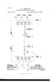
Be it known that I, FRANK R. MOBERT Y, a citizen of the United States, residing at Downers Grove,in the county of Du Page and State of Illinois, have invented a certain new and useful Improvement in Telephone-Exchange Apparatus, (Case No. 37,) of which the followingis a full, clear, concise, and exact description, reference being had to the accompanying drawing, forming a part of this specification.
My invention concerns the operation of telephone-lines grouped intelephone-exchanges and provided with earth returns or with ground branches.
' The invention consists in the application to such line-circuits of polarization or counter electromotive force cells in the circuits in such a way as to prevent the creation in them of currents arising from differences of potential at the different ground connections. It involves also certain groupings of the lines, whereby the greatest freedom from extraneous currents may be attained with the least apparatus. V
' The device which has been termed the polarization or counter-electromotive-force cell is well known to those skilled in electrical science. It may be an uniformed Plant storage-cell or any other pair of plates immersed in an electrolyte and adapted to become quickly polarized to oppose the passage through them of current in either direction.
The troublesome differences of potential between different points of the earth, which produce currents in grounded line-circuits connecting the different points, such as my invention is designed to avoid, are also familiar to those acquainted with the'art of telephony. These differences of potential are commonly found in the vicinity of electrical railways or other systems of electrical appliances conveying heavy currents through the earth. When the difierencesof potential arise from the currents used in the operation of railways, they vary in direction and in amount from time to time. In groundedlines extending from substations to a central station and including at the central station annuncia-tors responsive to signaling-currents from the substations currentsin the line arise from such difierences of potential between the grounds at the substations and that at the central station. The currents frequently op erate the line-annunciators or other signaling appliances connected with the lines. In the case of metallic circuit-line'ssuch as trunk lines-provided with ground branches for the purpose of transmitting signals currents from the same sources surge through the trunk lines, sometimes operating all the signaling devices connected with them. Great confusion and hindrance to the operators are thus occasioned.
My invention consists in interposing in the ground branches of the lines liable to such currents a number of polarization-cells suflicient to counteract any difference of potential acting upon the line and thus to prevent the creation in thecircuit of any appreciable current from the electromotive force in the earth. In special cases these cells may be included in the ground branches of each line;
. In other cases it may be found sufficient to interpose a series of cells in a commonground with the ordinary generators of signaling-current, polarized signal-bells, and telephones. The apparatus at the central station is also of usual character-a terminal spring-jack k and an annunciator l, responsive to signalingcurrent from the substation-generators, being' provided in the switchboard for each line. At each switchboard is located a pair of plugs m and m for uniting spring-jacks of diiferent lines, together with a clearing-out annunciator n for each pair of plugs. It is understood that each operator in the central office is equipped with a number of such pairs of plugs.
The trunk-line 1 is furnished with the usual automatic signaling appliances, comprising a signal-indicator 0 at one terminal station of the line, associated with the spring-jack p, which constitutes the terminal connection of the line, and a battery or other source of current g at the other station, and switch-contacts in the spring-jack 0', which constitutes the other terminal of the trunk-line for closing the circuit of the battery through the trunk-line under certain circumstances. The trunk-line here shown is intended to be used from station E as a call-initiating station to station I as a receiving-station. The system of signals is intended to become operative after connection has been made at station E and completed at station I and is designed to inform the operator at the latter station, through the instrumentality of signal 0, when the connecting-plug 'm is withdrawn from spring-jack 7*.
Since all of the lines, inclusive of the trunkline, are grounded circuits the system without the application of the present invention would be liable to the usual interference from extraneous currents arising from differences of potential at the different ground connections. Thus it may be assumed that the ground at station A is liable to become heavily electrified to a potential above or below the ground connection at the central office E. The grounds at stations B, O, and D being near together may be at positions of equally high or low potentials different from that of the central ground connect-ion. In such cases currents would tend to fiow through the different lines to the ground at the central office and to operate the line-annunciators there. Similarly differences of potential might arise between the ground connections of the trunkline at stations E and I, which would cause the operation of the automatic signal 0 during the insertion of plug m in the springjack and without relation to battery q, or in the event of a through connection between diifercnt lines centering in the different offices differences of potential between the earth connections at the united substations might cause the operation of the automatic trunk-line signals and thus effect premature disconnection of the lines.
In conformity with the present invention I interpose in each ground branch, where it is necessary, a polarization-cell or grqup of such cells sufficient in number to oppose the passage of any current through the line from a difference of potential between the ground connections of the line. Each polarizationcell will oppose a maximum counter electromotive force to current through it of approximately two volts. The differences of potential observed in telephone-lines in cities do not usually rise above twelve volts. Hence I consider six such polarization-cells to be a sufficient number for practical use. In interposing these cells in the lines I find it sufficient in most cases to place the polarization-cells only in the ground branches at the central office. In the case of lines like those to stat-ions B, O, and D, whose ground-terminals are subject to substantially equal electromotive forces, I find it sufficient to unite the ground connections at the central ofiice and to interpose in the common Wire there a group of polarization-cells. Any tendency to force current from ground at these stations to that at the central office is then opposed by the group of polarization-cells 8 without reference to the direction or, within the maximum counter electromotive force of the polarization-cells, to the voltage of the earth-potential. Since the ground connections at the stations are subject to the same influences, there is no tendency of current to flow in through one line and out through another line or group of lines. In the case of stations like A, however, which are subject to peculiar electrical conditions different from the generality of stations, I prefer to include a group of cells 25 in the substation ground connection also. Such cells of course prevent the flow of current over the line from the common ground-wire at the central office'. Stations F, G, and H have been treated in this way.
Ground connections from the clearing-out annunciators n and other appliances connected with the plug-circuit should of course also include polarization-cells. This connection from the plug-circuit at station E is made through the common group of polarizationcells 8 at that station. A similar branch from the plug-circuit at station I is shown with an individual group of polarization-cells u.
The interoffice trunk-line 1 is protected from extraneous currents by a group n in the ground branch 2, which includes the signal 0. In this case the battery g, which is designed to operate the signal, must be made of suificiently high electromotive force to overcome the opposition of the cells 12 and cause a current to traverse the signal 0.
The polarization-cells as ordinarily constructed are of exceedingly low internal resistance, and it is found that they transmit alternating or rapidly-undulating currents without any perceptible diminution. Hence the alternating currents commonly used in signaling between stations and the alternating or undulating telephonic currents find circuit through them without any sensible impairment.
Obviously a system equipped throughout with such groups of polarization-cells will be free from the troubles incident to varying earth-potentials.
I claim, broadly, as new and desire to secure by Letters Patent 1. The combination with a telephone-line grounded at two points subject to differences of potential and provided with a generator of annunciator at the other station, of a group of polarization-cells in one of the ground branches, substantially as described.
2. The combination with a system of telephone-lines grounded at points subject to differences of potential and provided with sources of signaling-current and with instruments responsive to such current, of polariza- 1o tion-cells in suitable ground connections to oppose the passage through the lines of current arising from such differences of potential, substantially as described.
In witness whereof I hereunto subscribe my name this 26th day of March, A. D. 1896.
FRANK R. MCBERTY.
Witnesses:
ELLA EDLER, LOLA J. BRINKERHOFF.
Publications (1)
| Publication Number | Publication Date |
|---|---|
| US587081A true US587081A (en) | 1897-07-27 |
Family
ID=2655750
Family Applications (1)
| Application Number | Title | Priority Date | Filing Date |
|---|---|---|---|
| US587081D Expired - Lifetime US587081A (en) | Telephone-exchange apparatus |
Country Status (1)
| Country | Link |
|---|---|
| US (1) | US587081A (en) |
-
0
- US US587081D patent/US587081A/en not_active Expired - Lifetime
Similar Documents
| Publication | Publication Date | Title |
|---|---|---|
| US574279A (en) | Charles e | |
| US563294A (en) | Apparatus for selective-signal systems | |
| US382476A (en) | Multiple switch-board | |
| US557153A (en) | Charles e | |
| US896103A (en) | Telephone system. | |
| US592422A (en) | kellogs | |
| US828061A (en) | Telephone-exchange system. | |
| US554399A (en) | Charles e | |
| US592326A (en) | Milo g | |
| US592419A (en) | Milo g | |
| US592315A (en) | Milo g | |
| US283312A (en) | Chables h | |
| US474854A (en) | Fhe nohris peters co | |
| US829164A (en) | Telephone trunking system. | |
| US574255A (en) | Telephone-exchange apparatus | |
| US563692A (en) | John s | |
| US544388A (en) | Charles e | |
| US845056A (en) | Telephone system. | |
| US564328A (en) | Of same place | |
| US584393A (en) | Telephone system | |
| US697993A (en) | Telephone-exchange system. | |
| US357540A (en) | Local battery-circuit for multiple-switch-board systems | |
| US592333A (en) | Milo g | |
| US632067A (en) | Multiple-switchboard system. | |
| US330060A (en) | Charles e |