US5867460A - Apparatus for laser beam exposure of a substrate disc - Google Patents

Apparatus for laser beam exposure of a substrate disc Download PDF

Info

Publication number
US5867460A
US5867460A US08/827,477 US82747796A US5867460A US 5867460 A US5867460 A US 5867460A US 82747796 A US82747796 A US 82747796A US 5867460 A US5867460 A US 5867460A
Authority
US
United States
Prior art keywords
laser beam
piezotranslator
internal part
beam objective
frame
Prior art date
Legal status (The legal status is an assumption and is not a legal conclusion. Google has not performed a legal analysis and makes no representation as to the accuracy of the status listed.)
Expired - Fee Related
Application number
US08/827,477
Inventor
Bernd Hensel
Friedrich Hofmann
Hermann Koop
Paul Kaiser
Eberhard Feick
Franz Richter
Current Assignee (The listed assignees may be inaccurate. Google has not performed a legal analysis and makes no representation or warranty as to the accuracy of the list.)
Balzers und Leybold Deutschland Holding AG
Original Assignee
Balzers und Leybold Deutschland Holding AG
Priority date (The priority date is an assumption and is not a legal conclusion. Google has not performed a legal analysis and makes no representation as to the accuracy of the date listed.)
Filing date
Publication date
Application filed by Balzers und Leybold Deutschland Holding AG filed Critical Balzers und Leybold Deutschland Holding AG
Priority to US08/827,477 priority Critical patent/US5867460A/en
Assigned to BALZERS UND LEYBOLD DEUTSCHLAND HOLDING AG reassignment BALZERS UND LEYBOLD DEUTSCHLAND HOLDING AG ASSIGNMENT OF ASSIGNORS INTEREST (SEE DOCUMENT FOR DETAILS). Assignors: HENSEL, BERND, HOFMAN, FRIEDRICH, KOOP, HERMANN, RICHTER, FRANZ, FEICK, EBERHARD, KAISER, PAUL
Application granted granted Critical
Publication of US5867460A publication Critical patent/US5867460A/en
Anticipated expiration legal-status Critical
Expired - Fee Related legal-status Critical Current

Links

Images

Classifications

    • GPHYSICS
    • G11INFORMATION STORAGE
    • G11BINFORMATION STORAGE BASED ON RELATIVE MOVEMENT BETWEEN RECORD CARRIER AND TRANSDUCER
    • G11B7/00Recording or reproducing by optical means, e.g. recording using a thermal beam of optical radiation by modifying optical properties or the physical structure, reproducing using an optical beam at lower power by sensing optical properties; Record carriers therefor
    • G11B7/24Record carriers characterised by shape, structure or physical properties, or by the selection of the material
    • G11B7/26Apparatus or processes specially adapted for the manufacture of record carriers
    • G11B7/261Preparing a master, e.g. exposing photoresist, electroforming

Definitions

  • the invention relates to an apparatus for exposing a substrate disc to a laser beam, which has a laser beam objective lens disposed in a mounting for displacement by means of piezoelectric translators, and a slide transversely displaceable in a table by means of a radial drive, the slide having a substrate holder disposed on a spindle driven by a rotary drive.
  • the substrate thicknesses vary in the nanometer range, while the irregularities are in the micron range. This results in different distances between the lens and the substrate surface and thus to a variation of the laser spot diameter on the substrate.
  • a moving-coil drive in accord with the varying distances. It has been found, however, that such drives do not have a sufficient dynamic range, so that irregulatories cannot be compensated due to excessively slow control, and therefore spot errors occur. This is true especially when operating at comparatively high recording velocities. In such a system, then, only substrates having very flat surfaces can be used, which are expensive to produce. Even then, recording speeds above 3 are not possible.
  • DE-A-38 28 145 has disclosed an apparatus for laser beam exposure of a substrate disc, in which the laser beam objective is mounted at the free end of a swiveling scanner arm.
  • a piezotranslator is disposed on the scanner arm, by which the scanner arm is able to execute a swiveling movement varying with the distance of the laser beam objective from the substrate.
  • An additional piezotranslator can swivel the to scanner arm in a plane at right angles thereto, which serves for the rapid track following readjustment or correction in the direction of the track.
  • U.S. Pat. No. 4,385,373 discloses an apparatus for laser beam exposure in which the laser beam objective is held in a frame of four memory-like piezo elements configured as flexural bodies. By the simultaneous actuation of all of the piezo elements, the latter can flex and thereby adjust the distance of the laser beam objective from the substrate.
  • the focal adjustment explained in this patent has the disadvantage that the varying flexing of the piezo elements results in a tilting of the laser beam objective lens. Since necessarily not all piezo elements have an absolute identical behavior, such tilting movements can never be entirely prevented, so that, again, the accuracy of the focal adjustment leaves something to be desired, although the four piezo elements would involve great cost in achieving rapid adjusting movements.
  • the object of the invention is for the laser beam objective to execute fast and precise adjusting motions, so that master discs can be produced at high speed and data densities.
  • fine adjustment of the laser beam objective relative to the direction of movement of the slide and/or fine focusing of the laser beam objective is accomplished by the piezotranslators provided on a linked block table which is configured for the linear displacement of the laser beam objective by a piezotranslator in only one direction, and for the linear displacement of the laser beam objective in a direction at right angles thereto and in line with the optical axis of the laser beam objective.
  • the linked block table forms a cross slide, such as the one familiar especially in lathes, which permits very precise adjusting movements for focusing and for correcting the tracing of the track.
  • the apparatus of the invention makes possible a high recording speed and great data density at relatively low cost.
  • the linked block table results in a high accuracy of guidance, so that the precise length changes of each piezotranslator can be converted to precise adjusting movements.
  • the linked block table has a frame which is to be fastened to a component and in which an internal part connected by links is disposed for displacement by the one piezotranslator in the one direction, and the internal part is fixedly attached to an internal part o a second linked block table which likewise has a frame which is disposed on the internal part for displacement by an additional piezotranslator in the other direction.
  • the piezotranslator is supported against the frame on the one hand and on the other hand against the internal part, and if the internal part is biased by a compression spring against the piezotranslator.
  • Tilting forces leading to adjustment errors can be excluded in a simple manner if, according to another embodiment of the invention, the piezotranslator thrusts through the medium of a ball against the frame and internal part, and the compression spring likewise thrusts via a ball against the internal part.
  • the linked block table is made especially compact if the internal part has a blind hole which the piezotranslator engages.
  • the correction of the position of the laser beam objective relative to the slide and thus relative to the substrate can be accomplished in a simple manner if, to determine the position of the slide relative to the laser beam objective, a measuring device with a scale is provided on the table and a sensor on the slide, and if means are provided for the modulation of the piezotranslator performing the horizontal displacement of the laser beam objective according to the signals of the sensor.
  • FIG. 1 is a side view of a preferred embodiment of an apparatus according to the invention
  • FIG. 2 is a plan view of the apparatus
  • FIG. 3 is a perspective view of a linked block table with adjacent components
  • FIG. 4 is a section taken through a piezotranslator according to the invention.
  • FIG. 1 shows a table 1 in which a slide 2 can be displaced on air bearings 3 transversely of the plane of drawing.
  • the slide 2 has a substrate holder 4 on which a substrate 5 serving as a master disc is held by suction.
  • the substrate holder 4 is provided on the upper end of a spindle 6 which in turn is held for rotation in an air bearing, not shown, of the slide 2.
  • a rotary drive 7 with a motor 8 serves for driving the spindle 6 and thus the substrate holder 4, and it is flange-mounted together with a rotary pulse generator 9 to the bottom end of the spindle 6.
  • a bridge 10 holding a laser beam objective 11 spans the table 1.
  • a radial drive 12 indicated in FIG. 2 serves to drive the slide 2.
  • the substrate 5 moves transversely of the laser beam objective 11, so that, due to the simultaneous rotation of the substrate holder 4 with the substrate 5, pits can be exposed on a spiral track on the substrate 5.
  • a measuring device 13 has a sensor 14 fastened as closely as possible to the objective, and a scale 15 fastened on the table and aligned in the direction of movement of the table 1.
  • a channel-shaped member 16 which reaches across the substrate and assures that the scale 15 runs immediately in front of the sensor 14.
  • the objective 11 is carried by a holder 17 which has a linear actuator 18 with a piezotranslator. This makes it possible to produce slight adjusting movements of the objective 11 on the axis of movement of the table 1.
  • FIG. 2 shows especially the alignment of the scale 15 in the direction of movement of the slide 2.
  • precise data on the position of the slide 2 relative to the laser beam objective 11 can constantly be obtained with the sensor 14. If, due to Inaccuracies of the radial drive 12, the data differ from the target data, the position is corrected by means of the actuator 18 by shifting the laser beam objective 11.
  • FIG. 3 shows two interconnected linked block tables 19 and 29.
  • the linked block table 19 is fixedly attached to the bridge 10 shown in FIG. 1. It has an internal part 21 which can be displaced relative to a frame 20 by a piezotranslator 24 in a horizontal plane.
  • the internal part 21 is affixed to the internal part 30 of the second linked block table 29 and, by means of a piezotranslator 31, can shift a frame 32 in the vertical direction.
  • This frame 32 bears the laser beam objective 11 shown in FIG. 1, which serves to expose the substrate 5 to the laser beam.
  • FIG. 4 shows a section through a linked block table 19. It consists of the above-mentioned continuous frame 20 and the internal part 21 which is displaceable to a limited degree therein.
  • This internal part 21 is connected to the frame 20 by four schematically indicated links 22.
  • the internal part 21 has a blind hole 23 into which a piezotranslator 24 composed of individual piezoelectric elements, and which thrusts through a ball 25 against the bottom of the blind hole 23 and with a ball 26 against the frame 20 or a component affixed to the latter.
  • a compression spring 27 which thrusts against the frame 20 at one end and at the other end thrusts through a ball 28 against the interior part 21 and thereby biases the internal part 21 against the piezotranslator 24.
  • the piezotranslator 24 changes its length in the nanometer range and therefore displaces the internal part 21 relative to the frame 20. If, for example, the frame 20 is fixed and the internal part 21 is connected to the laser beam objective 11, then in this manner slight adjusting movements of the laser beam objective 11 can be produced.

Abstract

In an apparatus for the laser beam exposure of a substrate disc (5), linked block tables (19, 29) are provided, which have each a piezotranslator (24, 31). This makes it possible to perform a fine correction of the movements very rapidly and very precisely.

Description

BACKGROUND OF THE INVENTION
The invention relates to an apparatus for exposing a substrate disc to a laser beam, which has a laser beam objective lens disposed in a mounting for displacement by means of piezoelectric translators, and a slide transversely displaceable in a table by means of a radial drive, the slide having a substrate holder disposed on a spindle driven by a rotary drive.
For the manufacture of master discs by which optically readable information media, such as compact discs, are produced, it is necessary that pits corresponding to the digital data be placed by the laser beam in precisely defined positions on a spiral track of a master disc. For this purpose, in addition to a precisely controlled rotatory speed, a very precise movement of the slide relative to the objective is necessary. Furthermore, it is necessary in the manufacture of such master discs to form a defined focal point, i.e., a light spot, on the photoresist coating of the substrate, with a defined spot diameter. This is accomplished with fixedly set end lens only if the substrate--usually a glass plate in practice--has always the same thickness and is absolutely flat at its surface. As a rule, the substrate thicknesses vary in the nanometer range, while the irregularities are in the micron range. This results in different distances between the lens and the substrate surface and thus to a variation of the laser spot diameter on the substrate. To prevent this it is known to adjust the end lens of the laser beam objective automatically by means of a moving-coil drive in accord with the varying distances. It has been found, however, that such drives do not have a sufficient dynamic range, so that irregulatories cannot be compensated due to excessively slow control, and therefore spot errors occur. This is true especially when operating at comparatively high recording velocities. In such a system, then, only substrates having very flat surfaces can be used, which are expensive to produce. Even then, recording speeds above 3 are not possible.
DE-A-38 28 145 has disclosed an apparatus for laser beam exposure of a substrate disc, in which the laser beam objective is mounted at the free end of a swiveling scanner arm. For focus control, a piezotranslator is disposed on the scanner arm, by which the scanner arm is able to execute a swiveling movement varying with the distance of the laser beam objective from the substrate. An additional piezotranslator can swivel the to scanner arm in a plane at right angles thereto, which serves for the rapid track following readjustment or correction in the direction of the track.
It is a disadvantage of the known apparatus that the adjustments produced by the piezotranslators result in an arcuate movement of the laser beam objective. This results in inaccuracies which limit the performance of the apparatus.
U.S. Pat. No. 4,385,373 discloses an apparatus for laser beam exposure in which the laser beam objective is held in a frame of four memory-like piezo elements configured as flexural bodies. By the simultaneous actuation of all of the piezo elements, the latter can flex and thereby adjust the distance of the laser beam objective from the substrate.
The focal adjustment explained in this patent has the disadvantage that the varying flexing of the piezo elements results in a tilting of the laser beam objective lens. Since necessarily not all piezo elements have an absolute identical behavior, such tilting movements can never be entirely prevented, so that, again, the accuracy of the focal adjustment leaves something to be desired, although the four piezo elements would involve great cost in achieving rapid adjusting movements.
SUMMARY OF THE INVENTION
The object of the invention is for the laser beam objective to execute fast and precise adjusting motions, so that master discs can be produced at high speed and data densities.
According to the invention, fine adjustment of the laser beam objective relative to the direction of movement of the slide and/or fine focusing of the laser beam objective is accomplished by the piezotranslators provided on a linked block table which is configured for the linear displacement of the laser beam objective by a piezotranslator in only one direction, and for the linear displacement of the laser beam objective in a direction at right angles thereto and in line with the optical axis of the laser beam objective.
In such an apparatus the linked block table forms a cross slide, such as the one familiar especially in lathes, which permits very precise adjusting movements for focusing and for correcting the tracing of the track. Thus, the apparatus of the invention makes possible a high recording speed and great data density at relatively low cost. The linked block table results in a high accuracy of guidance, so that the precise length changes of each piezotranslator can be converted to precise adjusting movements.
In an embodiment that is especially simple in design and very rigid, the linked block table has a frame which is to be fastened to a component and in which an internal part connected by links is disposed for displacement by the one piezotranslator in the one direction, and the internal part is fixedly attached to an internal part o a second linked block table which likewise has a frame which is disposed on the internal part for displacement by an additional piezotranslator in the other direction.
For further simplification of the design it is helpful if the piezotranslator is supported against the frame on the one hand and on the other hand against the internal part, and if the internal part is biased by a compression spring against the piezotranslator.
Tilting forces leading to adjustment errors can be excluded in a simple manner if, according to another embodiment of the invention, the piezotranslator thrusts through the medium of a ball against the frame and internal part, and the compression spring likewise thrusts via a ball against the internal part.
The linked block table is made especially compact if the internal part has a blind hole which the piezotranslator engages.
The correction of the position of the laser beam objective relative to the slide and thus relative to the substrate can be accomplished in a simple manner if, to determine the position of the slide relative to the laser beam objective, a measuring device with a scale is provided on the table and a sensor on the slide, and if means are provided for the modulation of the piezotranslator performing the horizontal displacement of the laser beam objective according to the signals of the sensor.
BRIEF DESCRIPTION OF THE DRAWING
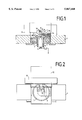
FIG. 1 is a side view of a preferred embodiment of an apparatus according to the invention,
FIG. 2 is a plan view of the apparatus,
FIG. 3 is a perspective view of a linked block table with adjacent components, and
FIG. 4 is a section taken through a piezotranslator according to the invention.
DETAILED DESCRIPTION OF THE PREFERRED EMBODIMENT
FIG. 1 shows a table 1 in which a slide 2 can be displaced on air bearings 3 transversely of the plane of drawing. The slide 2 has a substrate holder 4 on which a substrate 5 serving as a master disc is held by suction. The substrate holder 4 is provided on the upper end of a spindle 6 which in turn is held for rotation in an air bearing, not shown, of the slide 2. A rotary drive 7 with a motor 8 serves for driving the spindle 6 and thus the substrate holder 4, and it is flange-mounted together with a rotary pulse generator 9 to the bottom end of the spindle 6. A bridge 10 holding a laser beam objective 11 spans the table 1.
A radial drive 12 indicated in FIG. 2 serves to drive the slide 2. When the latter is working, the substrate 5 moves transversely of the laser beam objective 11, so that, due to the simultaneous rotation of the substrate holder 4 with the substrate 5, pits can be exposed on a spiral track on the substrate 5.
A measuring device 13 has a sensor 14 fastened as closely as possible to the objective, and a scale 15 fastened on the table and aligned in the direction of movement of the table 1. In FIG. 1 can be seen a channel-shaped member 16 which reaches across the substrate and assures that the scale 15 runs immediately in front of the sensor 14.
The objective 11 is carried by a holder 17 which has a linear actuator 18 with a piezotranslator. This makes it possible to produce slight adjusting movements of the objective 11 on the axis of movement of the table 1.
FIG. 2 shows especially the alignment of the scale 15 in the direction of movement of the slide 2. In this manner, precise data on the position of the slide 2 relative to the laser beam objective 11 can constantly be obtained with the sensor 14. If, due to Inaccuracies of the radial drive 12, the data differ from the target data, the position is corrected by means of the actuator 18 by shifting the laser beam objective 11.
FIG. 3 shows two interconnected linked block tables 19 and 29. The linked block table 19 is fixedly attached to the bridge 10 shown in FIG. 1. It has an internal part 21 which can be displaced relative to a frame 20 by a piezotranslator 24 in a horizontal plane. The internal part 21 is affixed to the internal part 30 of the second linked block table 29 and, by means of a piezotranslator 31, can shift a frame 32 in the vertical direction. This frame 32 bears the laser beam objective 11 shown in FIG. 1, which serves to expose the substrate 5 to the laser beam.
FIG. 4 shows a section through a linked block table 19. It consists of the above-mentioned continuous frame 20 and the internal part 21 which is displaceable to a limited degree therein. This internal part 21 is connected to the frame 20 by four schematically indicated links 22. The internal part 21 has a blind hole 23 into which a piezotranslator 24 composed of individual piezoelectric elements, and which thrusts through a ball 25 against the bottom of the blind hole 23 and with a ball 26 against the frame 20 or a component affixed to the latter.
In the bottom portion of FIG. 4 can be seen a compression spring 27 which thrusts against the frame 20 at one end and at the other end thrusts through a ball 28 against the interior part 21 and thereby biases the internal part 21 against the piezotranslator 24.
If the piezotranslator 24 is subjected to different tensions, it changes its length in the nanometer range and therefore displaces the internal part 21 relative to the frame 20. If, for example, the frame 20 is fixed and the internal part 21 is connected to the laser beam objective 11, then in this manner slight adjusting movements of the laser beam objective 11 can be produced.

Claims (6)

We claim:
1. Apparatus for the laser beam exposure of a substrate disk, which has a laser beam objective disposed for adjustment in a mounting by means of piezotranslators, and a slide which can be driven transversely thereto in a table by means of a radial drive and which has a substrate holder disposed on a spindle which can be driven by a rotary drive, wherein for the fine adjustment of the laser beam objective (11) relative to the direction of movement of the slide (2) and/or for the fine focusing of the laser beam objective (11), the piezotranslators (24, 31) are provided on a linked block table (19) which is configured for the linear displacement of the laser beam objective (11) by a piezotranslator (24) exclusively in one direction and for the linear displacement of the laser beam objective (11) in a direction at right angles thereto in line with the optical axis of the laser beam objective (11).
2. Apparatus according to claim 1, wherein the linked block table (19) has a frame (20) to be fastened to a component, and in said frame a first internal part (21) connected by links (22) is disposed for displacement by the one piezotranslator (24) in the one direction, the internal part (21) being affixed to a second internal part (30) of a second linked block table (29) which has a frame (32) disposed on the second internal part for displacement by an additional piezotranslator (31) in the other direction.
3. Apparatus according to claim 2, wherein the piezotranslator (24, 31) is thrust on the one hand against the frame (20, 32), and on the other hand against the internal part (21, 30), and that the internal part (21, 30) is biased by a compression spring (27) against the piezotranslator (24, 31).
4. Apparatus according to claim 3, wherein the piezotranslators (24, 32) thrust each with the interposition of a ball (25, 36) against the frame (20, 32) and against the internal part (21, 30) and the compression springs likewise thrust through a ball (28) against the internal part (21, 30).
5. Apparatus according to claim 2 wherein at least one of said internal parts (21, 30) has a blind hole (23) into which the piezotranslator (24, 31) reaches.
6. Apparatus according to claim 1 wherein for the determination of the position of the slide (2) relative to the laser beam objective (11) a measuring device (13) with a scale (15) is provided on the table (1), and a sensor (14) on the slide (2), and that means are provided for controlling the piezotranslator (24) that brings about the horizontal displacement of the laser beam objective in accord with the signals of the sensor (14).
US08/827,477 1996-10-04 1996-10-04 Apparatus for laser beam exposure of a substrate disc Expired - Fee Related US5867460A (en)

Priority Applications (1)

Application Number Priority Date Filing Date Title
US08/827,477 US5867460A (en) 1996-10-04 1996-10-04 Apparatus for laser beam exposure of a substrate disc

Applications Claiming Priority (1)

Application Number Priority Date Filing Date Title
US08/827,477 US5867460A (en) 1996-10-04 1996-10-04 Apparatus for laser beam exposure of a substrate disc

Publications (1)

Publication Number Publication Date
US5867460A true US5867460A (en) 1999-02-02

Family

ID=25249327

Family Applications (1)

Application Number Title Priority Date Filing Date
US08/827,477 Expired - Fee Related US5867460A (en) 1996-10-04 1996-10-04 Apparatus for laser beam exposure of a substrate disc

Country Status (1)

Country Link
US (1) US5867460A (en)

Citations (5)

* Cited by examiner, † Cited by third party
Publication number Priority date Publication date Assignee Title
EP0002547A1 (en) * 1977-12-12 1979-06-27 Koninklijke Philips Electronics N.V. Optical read unit for reading a moving information carrier, in particular for reading a video disc
US4375091A (en) * 1978-06-30 1983-02-22 Discovision Associates Method and apparatus for information retrieval from an optically readable storage medium
US4385373A (en) * 1980-11-10 1983-05-24 Eastman Kodak Company Device for focus and alignment control in optical recording and/or playback apparatus
US4794581A (en) * 1987-06-25 1988-12-27 International Business Machines Corporation Lens support system enabling focussing and tracking motions employing a unitary lens holder
EP0553664A2 (en) * 1992-01-30 1993-08-04 Hitachi, Ltd. Optical disk apparatus

Patent Citations (5)

* Cited by examiner, † Cited by third party
Publication number Priority date Publication date Assignee Title
EP0002547A1 (en) * 1977-12-12 1979-06-27 Koninklijke Philips Electronics N.V. Optical read unit for reading a moving information carrier, in particular for reading a video disc
US4375091A (en) * 1978-06-30 1983-02-22 Discovision Associates Method and apparatus for information retrieval from an optically readable storage medium
US4385373A (en) * 1980-11-10 1983-05-24 Eastman Kodak Company Device for focus and alignment control in optical recording and/or playback apparatus
US4794581A (en) * 1987-06-25 1988-12-27 International Business Machines Corporation Lens support system enabling focussing and tracking motions employing a unitary lens holder
EP0553664A2 (en) * 1992-01-30 1993-08-04 Hitachi, Ltd. Optical disk apparatus

Non-Patent Citations (1)

* Cited by examiner, † Cited by third party
Title
EPO Patent Abstracts of Japan; Title: Optical Head; Publ No 60211642; Publ Date Oct. 24, 1985; Appln No. 59066653; Appln Date Apr. 5, 1984; Applicant: NEC Corp.; Inventor Ishikawa Tsutomu. *

Similar Documents

Publication Publication Date Title
US7315503B2 (en) Optical pick-up device using micromirror array lens
US4464030A (en) Dynamic accuracy X-Y positioning table for use in a high precision light-spot writing system
US5068843A (en) Optical read-write apparatus
US6215738B1 (en) Device for reading from or writing to optical recording media
US5867460A (en) Apparatus for laser beam exposure of a substrate disc
US5025433A (en) Electro-optical device
US6226238B1 (en) Optical disc master recording device
JPH01112110A (en) Optical rotary encoder
US7180832B2 (en) Media driving apparatus
JPH09128777A (en) Apparatus for execution of laser beam exposure treatment to disk-shaped substrate
JP2895190B2 (en) Optical head device
EP0505156B1 (en) Tracking adjustment
KR100557523B1 (en) Skew automatic adjusting device and the control method of the objective lens
EP0572114B1 (en) An apparatus for driving an objective lens
JP2789493B2 (en) Optical head feed mechanism
CN1148238A (en) Recording/reproducing apparatus for disc-shaped recording medium
JPH01178143A (en) Optical disk device
JPS63144423A (en) Optical head device
JP2641403B2 (en) Reference signal generator for optical pickup
CN1270691A (en) Disc reproduction apparatus
JPH08329476A (en) Optical master disk exposure device and its control method
JPH03181027A (en) Optical recording and reproducing device
JPS62289928A (en) Tracking actuator for optical information recording and reproducing device
JPH06168472A (en) Optical recording and reproducing device
JPH0991744A (en) Optical pickup

Legal Events

Date Code Title Description
AS Assignment

Owner name: BALZERS UND LEYBOLD DEUTSCHLAND HOLDING AG, GERMAN

Free format text: ASSIGNMENT OF ASSIGNORS INTEREST;ASSIGNORS:HENSEL, BERND;HOFMAN, FRIEDRICH;KOOP, HERMANN;AND OTHERS;REEL/FRAME:008736/0203;SIGNING DATES FROM 19970711 TO 19970728

FEPP Fee payment procedure

Free format text: PAYOR NUMBER ASSIGNED (ORIGINAL EVENT CODE: ASPN); ENTITY STATUS OF PATENT OWNER: LARGE ENTITY

FPAY Fee payment

Year of fee payment: 4

REMI Maintenance fee reminder mailed
LAPS Lapse for failure to pay maintenance fees
STCH Information on status: patent discontinuation

Free format text: PATENT EXPIRED DUE TO NONPAYMENT OF MAINTENANCE FEES UNDER 37 CFR 1.362

FP Lapsed due to failure to pay maintenance fee

Effective date: 20070202

FEPP Fee payment procedure

Free format text: PAYER NUMBER DE-ASSIGNED (ORIGINAL EVENT CODE: RMPN); ENTITY STATUS OF PATENT OWNER: LARGE ENTITY

Free format text: PAYOR NUMBER ASSIGNED (ORIGINAL EVENT CODE: ASPN); ENTITY STATUS OF PATENT OWNER: LARGE ENTITY