US5867379A - Non-linear carrier controllers for high power factor rectification - Google Patents
Non-linear carrier controllers for high power factor rectification Download PDFInfo
- Publication number
- US5867379A US5867379A US08/371,822 US37182295A US5867379A US 5867379 A US5867379 A US 5867379A US 37182295 A US37182295 A US 37182295A US 5867379 A US5867379 A US 5867379A
- Authority
- US
- United States
- Prior art keywords
- voltage
- current
- input
- switching
- switch
- Prior art date
- Legal status (The legal status is an assumption and is not a legal conclusion. Google has not performed a legal analysis and makes no representation as to the accuracy of the status listed.)
- Expired - Fee Related
Links
Images


Classifications
-
- H—ELECTRICITY
- H02—GENERATION; CONVERSION OR DISTRIBUTION OF ELECTRIC POWER
- H02M—APPARATUS FOR CONVERSION BETWEEN AC AND AC, BETWEEN AC AND DC, OR BETWEEN DC AND DC, AND FOR USE WITH MAINS OR SIMILAR POWER SUPPLY SYSTEMS; CONVERSION OF DC OR AC INPUT POWER INTO SURGE OUTPUT POWER; CONTROL OR REGULATION THEREOF
- H02M1/00—Details of apparatus for conversion
- H02M1/42—Circuits or arrangements for compensating for or adjusting power factor in converters or inverters
- H02M1/4208—Arrangements for improving power factor of AC input
- H02M1/4225—Arrangements for improving power factor of AC input using a non-isolated boost converter
-
- Y—GENERAL TAGGING OF NEW TECHNOLOGICAL DEVELOPMENTS; GENERAL TAGGING OF CROSS-SECTIONAL TECHNOLOGIES SPANNING OVER SEVERAL SECTIONS OF THE IPC; TECHNICAL SUBJECTS COVERED BY FORMER USPC CROSS-REFERENCE ART COLLECTIONS [XRACs] AND DIGESTS
- Y02—TECHNOLOGIES OR APPLICATIONS FOR MITIGATION OR ADAPTATION AGAINST CLIMATE CHANGE
- Y02B—CLIMATE CHANGE MITIGATION TECHNOLOGIES RELATED TO BUILDINGS, e.g. HOUSING, HOUSE APPLIANCES OR RELATED END-USER APPLICATIONS
- Y02B70/00—Technologies for an efficient end-user side electric power management and consumption
- Y02B70/10—Technologies improving the efficiency by using switched-mode power supplies [SMPS], i.e. efficient power electronics conversion e.g. power factor correction or reduction of losses in power supplies or efficient standby modes
Definitions
- the present invention relates to switched mode power supplies, mainly boost converters, used to achieve high power factor rectification of the input AC line voltage.
- a non-linear carrier is compared to a signal derived from the switch current to obtain the pulse-width modulation signal.
- the pulse-width modulation signal drives the switch such that unity power factor results.
- AC-to-DC power rectifiers convert electric power from AC utility lines into DC voltages needed by a majority of electronic systems, including computers, home, and industrial electronics.
- Simple diode-bridge rectifiers pollute utility lines with large harmonic currents, which results in increased power losses and the inability to use all of the available power. Also, current harmonics may affect operation of sensitive equipment supplied from the same utility line. There exists a widespread need for high-quality rectification where AC power is taken with unity power factor and nearly zero current harmonics. The allowed level of current distortion is the subject of international regulations such as IEC-555-2 and IEEE-519.
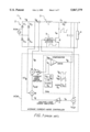
- the boost rectifier 1 shown in FIG. 1 illustrates the most widespread choice.
- the AC line voltage (ACIN) is connected to the AC inputs of the full-wave rectifier 2, consisting of diodes D1-D4.
- the full wave rectified line voltage v g appears at the input of the boost converter 3.
- the boost converter 3 consists of inductor L, power transistor switch Q, diode D5, and the output filter/energy-storage capacitor C.
- Load 4 is connected to the output DC voltage V across the output capacitor C.
- the power transistor switch Q is periodically turned on and off at a switching frequency f s much higher (f s is at least 20 kHz) than the line frequency (50 or 60 Hz).
- the duty ratio D defined as the ratio of the transistor on-time and the switching period T s , is the control variable that can be used to achieve unity power factor rectification.
- the goal is to obtain the input current i g proportional to the full-wave rectified line voltage v g ,
- the proportionality constant R e is called the emulated resistance, because the unity-power-factor rectifier behaves as a resistive load toward the AC line ACIN.
- FIG. 1 (prior art) also shows a block diagram of a frequently used control scheme called average current control.
- the average current mode controller ACM implements two feedback control loops in the boost rectifier.
- the first control loop is used to shape the input current i g to follow the input voltage waveform V g .
- the second control loop is used to regulate the output DC voltage V.
- the input current i g is sensed and compared to the reference current i ref creating error signal i e .
- the error signal is fed to the current-loop error amplifier A i .
- the output of the error amplifier is a modulating signal V m for the pulse width-modulator PWM.
- the modulating signal V m is compared to a saw-tooth carrier signal V c , periodic with period T s .
- the PWM carrier waveshape is given by the linear ramp ##EQU1## where V M is constant, and T s is the switching period.
- the modulator output is a periodic square-wave waveform V P , high when V c (t) ⁇ V m and low when V c (t) ⁇ V m . Therefore, the duty cycle of the modulator output waveform, ##EQU2## is proportional to the modulating input V m .
- the modulator output controls the on/off state of the main power switch Q through a suitable gate driver circuit 5.
- the main power switch Q controls the switch current i s to achieve the duty ratio D.
- the input current i g follows the reference proportional to the input voltage v g , so that the rectifier operates with near-unity power factor.
- the output voltage V is sensed and compared to a DC reference V ref .
- the error signal V e is fed to the voltage error amplifier A v .
- the output of the error amplifier V f controls the scale factor between the input voltage V g and the current reference i ref .
- a multiplier M is needed to implement this function, as shown in FIG. 1 (prior art). Assuming that the output of the error amplifier V f is a slowly varying signal, we have ##EQU3##
- the output voltage V is lower than the voltage reference V ref , v f increases, the emulated resistance R e decreases, and the power taken from the AC source ACIN increases resulting in the increase in the output voltage V, which tends to reduce the error.
- the steady-state output DC voltage V is equal to the desired reference V ref .
- One of the problems associated with the average current control technique of FIG. 1 is the need for sensing the input current i g using a series sense resistor R s . This results in increased power losses and an inability to isolate the controller ACM from the power stage 2.
- R s series sense resistor
- the switch current is sensed and compared to the reference signal proportional to the input line voltage.
- the peak current control has the advantage of sensing the switch current instead of the input line current. This eliminates the need for an error amplifier in the current-shaping loop. However, the resulting input current is distorted. Some improvements of the peak current control have been suggested in order to reduce the harmonic distortion in the input line current. However, it is still difficult to obtain optimum performance over wide ranges of load and line voltage variations.
- the multiplier and the voltage feedback loop are implemented as in FIG. 1.
- the peak current control is supported by dedicated integrated circuits from IC manufacturers such as Micro-Linear and Toko.
- both peak and valley of the inductor current are controlled by turning the main power switch off when the current reaches the upper reference value, and on when the current reaches the lower reference value.
- the input line current is forced to stay always between the two reference levels. If the two reference values are proportional to the input line voltage, the low-frequency portion of the inductor current is proportional to the input voltage, as required.
- Disadvantages of the hysteretic controller are that the inductor current sensing is needed, and that the converter operates at variable switching frequency.
- the multiplier and the voltage error amplifier are used as in FIG. 1. This control scheme is supported by a dedicated integrated circuit from Cherry Semiconductors.
- the simplest control technique is based on operating the boost converter in the discontinuous conduction mode (DCM). It has been shown that the DCM operation with fixed duty ratio results naturally in high power factor with relatively low harmonic distortion. The fixed duty ratio is controlled in the slow voltage loop to regulate the output voltage. Thus, no multiplier is needed in the controller implementation. Any of the standard PWM integrated circuits can be used to implement this control scheme. Unfortunately, the simplicity of the DCM control comes at the expense of much increased current stresses on the devices, increased conduction losses, and problems with filtering the large high-frequency current ripple from the inductor current. Also, the input current distortion cannot be completely eliminated. Therefore, the DCM control is preferred only in low-cost, low-power applications.
- DCM discontinuous conduction mode
- DCM control One modification of the DCM control is to operate the boost converter at the boundary between the continuous and discontinuous mode. This results in lower harmonic distortion, but at the expense of variable-frequency operation. Stesses are somewhat lower than in the DCM scheme, but are still high enough to invalidate the application of this control technique at higher power levels. This control scheme is also supported by dedicated integrated circuits from several manufacturers including Motorola and Silicon General.
- Cherry Semi-conductor--Application Note CS-3810 Control IC for Near Unity Power Factor in SMPS discloses the 16 pin Cherry Semiconductor CS-3810 Power Factor Correction IC.
- This IC has two multipliers, sample and hold circuitry, and various protection circuitry, for over and under voltage.
- the input and output voltage and switch current are sensed on the chip.
- the control method is a hysteretic current mode control. When the inductor current reaches the commanded peak and valley levels, the switch turns OFF and ON respectively.
- the multipliers are used to establish the peak and valley levels. As a result, the switching frequency varies with amplitude of the input voltage.
- U.S. Pat. No. 4,985,821 (1991) to Cohen discloses an invention which does not teach solving unity power factor for rectifiers. Instead, it discloses circuits for indirectly sensing and controlling the output current of switching type DC--DC converters.
- the circuit utilizes capacitance which follows the output voltage by being responsive to switching current during the conduction period and being controllably discharged as a function of output voltage during the non-conduction period. The result reflects the output current through both cycles of the switch.
- the present invention differs from this technique in that the present invention's capacitor is used to integrate the switch current over the switch cycle. This integrated switch current is then compared to a periodic non-linear carrier waveform constructed so that the input current follows the input line voltage as required for unity power factor rectification.
- the present invention requires sensing only the switch current and output voltage. Thus, the present invention can be implemented in a simpler and cheaper integrated circuit.
- the primary object of the present invention is to provide a unity power factor at the input of a power supply by only sensing the switch current and the output voltage.
- New non-linear carrier pulse-width modulators for control of high-power-factor boost and other rectifiers are disclosed.
- the main power switch turn-off time and the switch duty ratio are determined by comparing a signal derived from the main switch current with a periodic, nonlinear carrier signal v c (t,v m ).
- Two versions of modulators are described: the charge non-linear carrier modulator, where the signal proportional to the integral of the switch current is compared to the carrier, and the peak current non-linear carrier modulator, where the signal proportional to the switch current is compared to the carrier.
- the distinctive feature of the new modulators is the non-linear carrier signal v c (t,v m ).
- the carrier signal is periodic with the period equal to the switching period, and its waveshape is determined so that the resulting input line current is proportional to the input line voltage, as required for unity-power-factor rectification.
- the emulated resistance and, therefore, the power level can be adjusted by a slowly-varying modulating signal v m .
- Simple schemes for carrier synthesis in the two modulators are also described.
- the controller based on one of the non-linear carrier modulators is simpler because:
- the current-shaping is based on the switch current sensing, which is the most favorable option for practical implementation. Compared to sensing the input line or inductor current, the switch current sensing is more efficient and less noise sensitive. It also offers the possibility of electrical isolation between the controller and the power stage.
- the controller is suitable for boost configurations where the input ac line and the controller are electrically isolated or where the controller reference ground is floating with respect to the ac line.
- the controller is suitable for boost rectifiers operating in the continuous conduction mode, which is the preferred mode of operation because of the lower noise levels and lower component stresses compared to the discontinuous conduction mode.
- the controller is well-suited for a low-cost integrated-circuit based on the non-linear carrier modulators disclosed here.
- the controller would be simpler and would require less i/o pins than currently available integrated circuits, while offering comparable or improved performance.
- the charge non-linear carrier modulator has the advantage of somewhat simpler carrier signal, and better current-sense noise immunity because the sensed switch current is integrated.
- the peak current non-linear carrier modulator has the advantage of inherent instantaneous over-current protection for the transistor switch.
- FIG. 1 (Prior Art) High-Power-Factor boost rectifier with a block diagram of the average current mode controller.
- FIG. 2 is a high power factor boost rectifier with a charge non-linear carrier controller.
- FIG. 3 is the key waveform of the boost rectifier shown in FIG. 2.
- FIG. 4 is a block diagram of the carrier generator for the charge non-linear carrier controller of FIG. 2.
- FIG. 5 is the key waveforms of the modulator of FIG. 4.
- FIG. 6 is a high power factor boost rectifier with a peak current non-linear carrier controller.
- FIG. 7 is the key waveform of the boost rectifier shown in FIG. 6.
- FIG. 8 is a block diagram of carrier generator for the charge non-linear carrier controller of FIG. 6.
- FIG. 9 is the key waveforms of the modulator of FIG. 8.
- FIG. 10 shows the input current and voltage of the breadboard circuit.
- FIG. 11 shows the transistor drive voltage, and the input to the comparitor of the breadboard circuit of FIG. 10.
- the converter operates in the continuous conduction mode
- the switching frequency f s is much higher than the line frequency f t
- the input voltage v g is a full-wave rectified sinewave. During one switching interval, the input voltage can be considered constant;
- the output voltage V is approximately constant during one half line cycle
- Averaging a switching waveform in this manner yields the low-frequency components of the waveform and is a well-accepted approximation in the Power electronics field.
- a modulator is derived where the cycle-by-cycle average of the switch current is compared to a judiciously selected non-linear carrier waveform.
- a control scheme based on evaluating the cycle-by-cycle average of a switching waveform was proposed in Schwarz (184). More recently, a similar approach to control of switch-mode power converters, known as charge control, was presented in Tang et al. (IEEE PESC, 1992, pp. 503-511).
- the distinctive feature of the charge feed-forward modulator described here is that the cycle-by-cycle average of the switch current is compared to a periodic non-linear carrier waveform constructed so that the input current in the boost rectifier automatically follows the input line voltage, as required for unity power factor rectification.
- the rectifier emulated resistance is given by ##EQU11## Therefore, the slowly-varying modulating input v m can be used to control the emulated resistance and the power level in the output voltage regulation loop without need for a multiplier.
- FIG. 2 shows a charge non-linear carrier controller 27 configured as a boost rectifier.
- FIG. 3 shows typical switching waveforms for the charge non-linear controller shown in FIG. 2.
- the AC line voltage 6 is connected to the AC inputs of the full-wave diode bridge rectifier 28 consisting of four diodes 7-10.
- the output of the diode bridge rectifier 28 generates the full wave rectified line voltage V 1 and input current i 1 at the input of the boost converter 29.
- the boost converter consists of inductor 11, power transistor 12, diode 13, and the output capacitor 14.
- the load 15 is connected to the output dc voltage V 15 across the output capacitor 14.
- the boost converter 29 is controlled by the charge non-linear controller NLC.
- the main power transistor 12 is periodically turned on and off at a switching frequency f s much higher than the line frequency by the gate driver 25.
- narrow clock pulse V 24 generated by the clock 24, sets the set/reset flip-flop 23.
- V 23 goes high turning on the power transistor 12 via the gate driver 25.
- V 23 also opens the switch 21 allowing the integrator capacitor 22 to charge.
- the integrator capacitor 22 is located in the integrator with reset 26, thus the switch cycle is started.
- the output voltage V 15 is summed with the reference voltage V 14 by the summing junction 16.
- Summing junction 16 produces an error voltage V 16 which is multiplied by the gain of the voltage loop error amplifier 17 to obtain the modulating input V 17 .
- the carrier generator 18, which is also reset by the clock signal V 24 transforms the modulating input V 17 into the carrier signal V 18 as shown in FIGS. 4 and 5.
- the power transistor current i 12 is sensed and used to charge the integrator capacitor 22 to produce integrator output signal V22.
- the integrator output signal V 22 is compared to the carrier signal V 18 by comparitor 19. When the integrator output signal V 22 reaches the voltage level of the carrier signal V 18 , the comparitor output V 19 resets the flip flop 23, the power switch 12 is turned off, and the integrator capacitor 22 is reset to zero, thus ending the switch cycle.
- FIG. 4 A block diagram of the v c (t) generator 18 of FIG. 2 is shown in FIG. 4, together with waveforms illustrating the operation shown in FIG. 5.
- the capacitor 53 is discharged to zero using a switch 54 controlled by the clock input signal 55.
- the output of the integrator with reset 51 is the linear ramp signal v 1 (t) 56.
- the second step is to subtract v m 57 from v 1 (t) 56, obtaining V 2 (t) 58 as shown in the block diagram.
- v c (t) 63 is obtained by integrating v 2 (t) 58, ##EQU13## which is the function of the second integrator with reset 59 comprising current source 60, capacitor 61, and switch 62. Both integrators 51 and 59 are reset to zero by the clock signal 55 at the beginning of every switching cycle to ensure the correct zero initial conditions.
- a non-linear carrier modulator is derived wherein the sensed switch current is compared to a judiciously selected non-linear carrier waveform.
- the sensed switch current is also used in the peak-current control schemes for power-factor correction (as shown in Nalbant et al. Power Conversion, October 1989 Proceedings, pp. 121-134 and the TOKO IC Data Book 1993 power factor controllers: TK81854 and TK84812).
- the distinctive feature of the peak current feed-forward modulator described here is that the sensed switch current is compared to the periodic nonlinear carrier waveform constructed so that the input current in the boost rectifier automatically follows the input line voltage, as required for unity power factor rectification.
- FIG. 6 shows a peak current non-linear carrier controller 127 configured as a boost rectifier.
- FIG. 7 shows typical switching waveforms for the peak current non-linear controller shown in FIG. 6.
- the AC line voltage 106 is connected to the AC inputs of the full-wave diode bridge rectifier 128 consisting of four diodes 107-110.
- the output of the diode bridge rectifier 128 generates the full wave rectified line voltage V 101 and input current i 101 at the input of the boost converter 129.
- the boost converter consists of inductor 111, power transistor 112, diode 113, and the output capacitor 114.
- the load 115 is connected to the output dc voltage V 115 across the output capacitor 114.
- the boost converter 129 is controlled by the peak current non-linear carrier controller PNC.
- the main power transistor 112 is periodically turned on and off at a switching frequency f s much higher than the line frequency by the gate driver 125.
- a narrow clock pulse V 124 generated by the clock 124, sets the set/reset flip-flop 123.
- V 123 goes high turning on the power transistor 112 via the gate driver 125, thus the switch cycle is started.
- the output voltage V 115 is summed with the reference voltage V 114 by the summing junction 116.
- Summing junction 116 produces an error voltage V 116 which is multiplied by the gain of the voltage loop error amplifier 117 to obtain the modulating input V 117 .
- the carrier generator 118 which is also reset by the clock signal V 124 , transforms the modulating input V 117 into the carrier signal V 118 as shown in FIGS. 6 and 7.
- the power transistor current i 112 is sensed and used to generate the switch current signal V 122 .
- the switch current signal V 122 is compared to the carrier signal V 118 by the comparitor 119.
- FIG. 7 V 123 and V 124 shows the relationship between the duty ratio D and the switching period T s . This process maintains the input current i 101 at the same phase and frequency as the input voltage V 101 .
- the output load 115 is also supplied with the output current i 115 required to maintain the output voltage V 115 at the same level as the reference voltage V 114 .
- An optional zener diode 130 placed on the carrier signal V 118 will limit the power transistor current i 112 to a desired maximum current.
- FIG. 8 A block diagram of the v c (t) generator 118 of FIG. 6 is shown in FIG. 8, together with waveforms illustrating the operation shown in FIG. 9.
- the capacitor 153 is discharged to zero using a switch 154 controlled by the clock input signal 155.
- the output of the integrator with reset 151 is the linear ramp signal 156 V 1 .
- the second step is to add V m 157 and subtract K 165 from v 1 (t) 156 obtaining V 2 158, as shown in the block diagram.
- v 3 (t) 164 is obtained by integrating v 2 (t) 158, ##EQU18## which is the function of the second integrator with reset 159 comprising controlled current source 160, capacitor 161, and switch 162.
- V c 163 is obtained by adding the modulating input V m 157 to V 3 164.
- Both integrators 151 and 159 are reset to zero by the clock signal 155 at the beginning of every switching cycle to ensure the correct zero initial conditions.
- the block diagram of the circuit shown in FIG. 2 has been implemented in a bread-board.
- FIG. 10 shows an oscilloscope trace of the input current i 1 and the input voltage V 1 of the breadboard on channel 1 and channel 2 respectively.
- the scale factor for channel 1 is 1A/div.
- the scale factor for channel 2 is 50V/div.
- the figure shows that the input phase and frequency are the same. Thus, unity power factor has been achieved.
- FIG. 11 shows the measured values of the carrier generator output V 18 , the integrated switch current V 22 , and the resultant input to the gate driver V 23 . These waveforms are the same as the predicted waveforms shown in FIG. 3.
Abstract
Description
______________________________________
GLOSSARY
______________________________________
Apparent Power
           The RMS current times the RMS voltage in
           a load.
Boost Converter
           A switching power supply with an input
           inductor that stores energy and a shunt
           switch in parallel with the load.
           Produces a higher voltage at the output.
Buck Converter
           A switching power supply that has a
           switch in series with an inductive-
           capacitive filter. Produces an output
           voltage lower than the input voltage
Capacitor  A capacitor stores electric energy,
           blocks the flow of direct current, and
           permits the flow of alternating current
           to a degree depending on the capacitance
           and the frequency. The voltage across a
           capacitor cannot change instantaneously.
           Current changes lead voltage changes in
           a capacitor. The relationship between
           current and voltage is: I = C dV/dt.
Continuous Operation of a converter such that
Conduction Mode
           switch turns on at non-zero current.
(CCM)
Converter  A circuit for converting DC to AC. A
           circuit for converting AC to DC. A
           circuit for converting DC to DC.
Current Injection
           Uses the instantaneous inductor current
Control (CIC)
           as part of the control signals. Same as
           Peak Current Mode Control.
Discontinuous
           Opposite of CCM. The switch turns on at
Conduction Mode
           zero current.
(DCM)
Flyback Converter
           A buck-boost switching power supply with
           a single switching transistor that
           eliminates the output inductor. Energy
           is stored in the transformer primary
           when the transistor is conducting. When
           the transistor is off (the flyback
           period) the energy is transferred to the
           transformer secondary and load.
Inductor   An inductor stores electric energy,
           blocks the flow of alternating current
           to a degree depending on the inductance
           and frequency and permits the flow of
           direct current. The current through an
           inductor cannot change instantaneously.
           The relationship between current and
           voltage is: V = L di/dt.
Peak Current Mode
           Uses the instantaneous inductor current
Control    as part of the control signals. Same as
           Current Injection Control.
Power Factor
           The ratio of true power to apparent
           power as a percentage. Power factor is
           equal to the cosine of the phase angle
           between the current and the voltage when
           both are sinusoidal.
Reactive Power
           The imaginary portion of apparent power.
RMS        Root mean squared.
SMPS       Switched Mode Power Supply
Transformer
           A component that consists of two or more
           inductors which are coupled together by
           magnetic induction. The current and
           voltage are transformed across the
           transformer without changing the
           frequency.
            ##STR1##
True Power The real portion of apparent power.
______________________________________
i.sub.g =ν.sub.g /R.sub.e ( 1)
i.sub.s =Di.sub.1 (6)
ν.sub.g =(1-D)V (7)
ν.sub.c (t.sub.off)=ν.sub.q (t.sub.off), (15)
ν.sub.c (t)=ν.sub.m (1-t/T.sub.s)+K(t/T.sub.s)(1-t/T.sub.s)=(ν.sub.m +Kt/T.sub.s)(1-t/T.sub.s), (21)
Claims (13)
Priority Applications (1)
| Application Number | Priority Date | Filing Date | Title |
|---|---|---|---|
| US08/371,822 US5867379A (en) | 1995-01-12 | 1995-01-12 | Non-linear carrier controllers for high power factor rectification |
Applications Claiming Priority (1)
| Application Number | Priority Date | Filing Date | Title |
|---|---|---|---|
| US08/371,822 US5867379A (en) | 1995-01-12 | 1995-01-12 | Non-linear carrier controllers for high power factor rectification |
Publications (1)
| Publication Number | Publication Date |
|---|---|
| US5867379A true US5867379A (en) | 1999-02-02 |
Family
ID=23465546
Family Applications (1)
| Application Number | Title | Priority Date | Filing Date |
|---|---|---|---|
| US08/371,822 Expired - Fee Related US5867379A (en) | 1995-01-12 | 1995-01-12 | Non-linear carrier controllers for high power factor rectification |
Country Status (1)
| Country | Link |
|---|---|
| US (1) | US5867379A (en) |
Cited By (107)
| Publication number | Priority date | Publication date | Assignee | Title |
|---|---|---|---|---|
| US5982644A (en) * | 1998-12-16 | 1999-11-09 | Hughes Electronics Corporation | Voltage boost circuit for a high voltage converter |
| US6011382A (en) * | 1998-10-01 | 2000-01-04 | Toko, Inc. | Circuit and method for directly regulating the output voltage of an electroluminescent lamp driver |
| US6049473A (en) * | 1999-02-11 | 2000-04-11 | Delta Electronics, Inc. | Harmonic-injection control technique for three-phase, discontinuous-conduction-mode, high-power-factor boost rectifiers with improved line-transient response |
| US6160385A (en) * | 1998-09-30 | 2000-12-12 | Siemens Aktiengesellschaft | Circuit configuration for producing a load-independent output voltage |
| US6169668B1 (en) * | 1999-10-27 | 2001-01-02 | Space Systems/Loral, Inc. | Zero voltage switching isolated boost converters |
| US6172885B1 (en) * | 1998-04-01 | 2001-01-09 | Infineon Technologies Ag | Switched-mode power supply with mains current consumption regulation |
| US6172492B1 (en) * | 1999-03-26 | 2001-01-09 | Sarnoff Corporation | Fixed off time and zero voltage switching dual mode power factor correcting converter |
| US6188588B1 (en) * | 1999-10-07 | 2001-02-13 | International Business Machine Corporation | Switching controller and method for operating a flyback converter in a critically continuous conduction mode |
| US6191565B1 (en) * | 1999-06-14 | 2001-02-20 | Fairchild Korea Semiconductor Ltd. | Power factor compensation controller |
| US6259614B1 (en) * | 1999-07-12 | 2001-07-10 | International Rectifier Corporation | Power factor correction control circuit |
| US6295216B1 (en) * | 2000-04-06 | 2001-09-25 | Powerware Corporation | Power supply apparatus with selective rectifier harmonic input current suppression and methods of operation thereof |
| US6320733B1 (en) * | 1997-02-26 | 2001-11-20 | Infineon Technologies Ag | Pulse-width modulator for controlling a semiconductor circuit breaker |
| US6388429B1 (en) * | 2000-03-09 | 2002-05-14 | Hengchun Mao | Controller for power factor corrector and method of operation thereof |
| US6396725B1 (en) * | 2000-07-31 | 2002-05-28 | Mark E. Jacobs | System and method for improving control loop response of a power supply |
| US6465992B2 (en) * | 2000-12-13 | 2002-10-15 | Koninklijke Philips Electronics N.V. | Preconditioner generating feedback signal having reduced ripple |
| US6657417B1 (en) | 2002-05-31 | 2003-12-02 | Champion Microelectronic Corp. | Power factor correction with carrier control and input voltage sensing |
| US20030222633A1 (en) * | 2002-05-31 | 2003-12-04 | Champion Microelectronic Corp. | Switching power supply having alternate function signal |
| US6671143B2 (en) | 2001-03-30 | 2003-12-30 | Champion Microelectronic Corp. | Technique for limiting current through a reactive element in a voltage converter |
| US20040095101A1 (en) * | 2002-08-01 | 2004-05-20 | Stmicroelectronics S.R.L. | Device for the correction of the power factor in power supply units with forced switching operating in transition mode |
| US20040130304A1 (en) * | 2003-01-03 | 2004-07-08 | Comarco Wireless Technologies, Inc. | Voltage regulator having a voltage doubler device |
| US20040174152A1 (en) * | 2003-03-04 | 2004-09-09 | Hwang Jeffrey H. | Pulse-skipping switching power converter |
| US20050007083A1 (en) * | 2003-07-10 | 2005-01-13 | Ta-Yung Yang | Power supply having multi-vector error amplifier for power factor correction |
| US20050013147A1 (en) * | 2003-06-04 | 2005-01-20 | Universidad De Santiago De Chile | Method and apparatus to reduce distortion of currents feeding an AC/DC rectifier system |
| US20050110474A1 (en) * | 2003-11-24 | 2005-05-26 | Ortiz Joe A. | Method for input current regulation and active-power filter with input voltage feedforward and output load feedforward |
| US20050174813A1 (en) * | 2004-02-06 | 2005-08-11 | Delta Electronics, Inc. | High efficiency power converter with synchronous rectification |
| US20050231176A1 (en) * | 2004-04-20 | 2005-10-20 | Yu-Fen Liao | Conversion circuit for discriminating sourcing current and sinking current |
| US20050237041A1 (en) * | 2004-04-26 | 2005-10-27 | Weng Da F | Quasi average current mode control scheme for switching power converter |
| US20050243488A1 (en) * | 2004-04-29 | 2005-11-03 | Tracy John G | Power converter apparatus and methods using a phase reference derived from a DC bus voltage |
| US20050253565A1 (en) * | 2004-05-13 | 2005-11-17 | Isaac Cohen | Method and Control Circuit for Power Factor Correction |
| US20050254265A1 (en) * | 2002-08-12 | 2005-11-17 | Toyota Jidosha Kabushiki Kaisha | Voltage conversion device, voltage conversion method, and computer-readable recording medium containing program causing computer to execute voltage conversion |
| US20060002162A1 (en) * | 2004-06-30 | 2006-01-05 | Rong-Jie Tu | Single inductor capacitor charger |
| US20060022648A1 (en) * | 2004-08-02 | 2006-02-02 | Green Power Technologies Ltd. | Method and control circuitry for improved-performance switch-mode converters |
| US20060043942A1 (en) * | 2004-05-13 | 2006-03-02 | Isaac Cohen | Power converter apparatus and methods using output current feedforward control |
| US20060091872A1 (en) * | 2004-10-28 | 2006-05-04 | Tdk Corporation | Switching power supply control device and switching power supply |
| US20060097710A1 (en) * | 2004-11-09 | 2006-05-11 | Texas Instruments Inc. | Current sensing circuitry for DC-DC converters |
| WO2006112991A2 (en) | 2005-04-19 | 2006-10-26 | Raytheon Company | Method and control circuitry for providing average current mode control in a power converter and an active power filter |
| US20060267542A1 (en) * | 2005-05-27 | 2006-11-30 | Lixiang Wei | Pulse width modulation (PWM) rectifier with variable switching frequency |
| US20060285373A1 (en) * | 2003-02-04 | 2006-12-21 | Michael Archer | Power factor correction circuit |
| US7315150B1 (en) * | 2006-03-30 | 2008-01-01 | Integrated Circuit Design, Inc. | Method of power conversion and apparatus which achieves high power factor correction using ripple current mode control |
| US20080067993A1 (en) * | 2006-09-16 | 2008-03-20 | Texas Instruments Incorporated | Frequency Regulated Hysteretic Average Current Mode Converter |
| US20080122422A1 (en) * | 2004-06-04 | 2008-05-29 | Iwatt Inc. | Parallel Current Mode Control Using a Direct Duty Cycle Algorithm with Low Computational Requirements to Perform Power Factor Correction |
| US20080211462A1 (en) * | 2007-03-04 | 2008-09-04 | Beelab Semiconductor Ltd. | Method and apparatus for active power factor correction |
| US7433211B1 (en) * | 2003-06-30 | 2008-10-07 | Iwatt Inc. | System and method for input current shaping in a power converter |
| US20080272745A1 (en) * | 2007-05-02 | 2008-11-06 | Cirrus Logic, Inc. | Power factor correction controller with feedback reduction |
| US20080285319A1 (en) * | 2007-05-18 | 2008-11-20 | Deisch Cecil W | Method and apparatus achieving a high power factor with a flyback transformer |
| KR100902469B1 (en) | 2001-09-17 | 2009-06-11 | 엔엑스피 비 브이 | Converter for converting an input voltage to an output voltage |
| US7564706B1 (en) * | 2006-06-23 | 2009-07-21 | Edward Herbert | Power factor corrected single-phase AC-DC power converter using natural modulation |
| US7609037B1 (en) * | 2006-06-23 | 2009-10-27 | Edward Herbert | “Natural modulation” for maximizing efficiency in power converters |
| US20100014329A1 (en) * | 2008-07-18 | 2010-01-21 | Yong Zhang | Enhanced one cycle control for power factor correction |
| US20100013412A1 (en) * | 2008-07-15 | 2010-01-21 | Intersil Americas Inc | Transient suppression for boost regulator |
| US20100067270A1 (en) * | 2008-09-15 | 2010-03-18 | Power Integrations, Inc. | Method and apparatus to reduce line current harmonics from a power supply |
| US20100118571A1 (en) * | 2008-11-07 | 2010-05-13 | Power Integrations, Inc. | Method and apparatus to control a power factor correction circuit |
| US20100118573A1 (en) * | 2008-11-07 | 2010-05-13 | Power Integrations, Inc. | Method and apparatus to increase efficiency in a power factor correction circuit |
| US20110031911A1 (en) * | 2009-08-10 | 2011-02-10 | Emerson Climate Technologies, Inc. | Power factor correction with variable bus voltage |
| US20110031942A1 (en) * | 2009-08-10 | 2011-02-10 | Emerson Climate Technologies, Inc. | System and method for reducing line current distortion |
| US20110031920A1 (en) * | 2009-08-10 | 2011-02-10 | Emerson Climate Technologies, Inc. | Controller and method for estimating, managing, and diagnosing motor parameters |
| US20110031940A1 (en) * | 2009-08-10 | 2011-02-10 | Emerson Climate Technologies, Inc. | System and method for power factor correction frequency tracking and reference generation |
| US20110031914A1 (en) * | 2009-08-10 | 2011-02-10 | Emerson Climate Technologies, Inc. | Controller and method for transitioning between control angles |
| US20110031941A1 (en) * | 2009-08-10 | 2011-02-10 | Emerson Climate Technologies, Inc. | System and method for current balancing |
| US20110031943A1 (en) * | 2009-08-10 | 2011-02-10 | Emerson Climate Technologies, Inc. | System and method for rejecting dc current in power factor correction systems |
| US20110032738A1 (en) * | 2009-08-10 | 2011-02-10 | Emerson Climate Technologies, Inc. | System and method for power factor correction |
| US20110075448A1 (en) * | 2009-09-30 | 2011-03-31 | Melanson John L | Switching power converter controller with direct current transformer sensing |
| CN101299574B (en) * | 2007-03-04 | 2011-05-25 | 蜜蜂工房半导体有限公司 | Method and apparatus for active power factor correction without sensing the line voltage |
| US20110211377A1 (en) * | 2008-11-25 | 2011-09-01 | Murata Manufacturing Co., Ltd. | Power factor correction converter |
| US20110291628A1 (en) * | 2010-06-01 | 2011-12-01 | Frank Beny | Switching regulator circuit and method for providing a regulated voltage |
| US20120051107A1 (en) * | 2010-08-26 | 2012-03-01 | Choi Hangseok | Method and apparatus for bridgeless power factor correction |
| CN101594066B (en) * | 2008-05-26 | 2012-04-18 | 上海海事大学 | Normalized nonlinear PWM carrier modulating method of current transformer |
| US20120235649A1 (en) * | 2009-03-18 | 2012-09-20 | Murata Manufacturing Co., Ltd. | Power factor correction converter |
| US20120236612A1 (en) * | 2009-03-24 | 2012-09-20 | Murata Manufacturing Co., Ltd. | Switching power supply apparatus |
| WO2012149518A2 (en) | 2011-04-28 | 2012-11-01 | Texas Instruments Incorporated | Power conversion system and method |
| US20130148396A1 (en) * | 2011-12-09 | 2013-06-13 | Intersil Americas LLC | System and method of feed forward for boost converters with improved power factor and reduced energy storage |
| US20130170265A1 (en) * | 2010-09-28 | 2013-07-04 | Mitsubishi Electric Corporation | Power conversion apparatus |
| US20130294121A1 (en) * | 2005-08-18 | 2013-11-07 | On-Bright Electronics (Shanghai) Co., Ltd. | System and method providing over current and over power protection for power converter |
| US20140071718A1 (en) * | 2012-09-12 | 2014-03-13 | Excelliance Mos Corporation | Fly-back power converting apparatus |
| US20140085947A1 (en) * | 2012-09-27 | 2014-03-27 | Jose M. Capilla | Off-line power converter and integrated circuit suitable for use in same |
| US8698433B2 (en) | 2009-08-10 | 2014-04-15 | Emerson Climate Technologies, Inc. | Controller and method for minimizing phase advance current |
| CN103731022A (en) * | 2012-10-15 | 2014-04-16 | 英飞凌科技股份有限公司 | Active power factor corrector circuit |
| CN103996389A (en) * | 2014-05-08 | 2014-08-20 | 京东方科技集团股份有限公司 | Power supply circuit and display device |
| JP5611497B1 (en) * | 2014-01-21 | 2014-10-22 | 三菱電機株式会社 | Semiconductor power converter |
| US20150016166A1 (en) * | 2013-07-10 | 2015-01-15 | Supertex, Inc. | Line Current Reference Generator |
| US20150061614A1 (en) * | 2013-08-27 | 2015-03-05 | Texas Instruments Incorporated | Method and apparatus for calculating an average value of an inaccessible current from an acessible current |
| US20150123636A1 (en) * | 2011-01-31 | 2015-05-07 | Infineon Technologies Austria Ag | Cuk Based Current Source |
| US20150370273A1 (en) * | 2010-11-30 | 2015-12-24 | Taiwan Semiconductor Manufacturing Company, Ltd. | Hysteretic power converter with calibration circuit |
| US9240749B2 (en) | 2012-08-10 | 2016-01-19 | Emerson Climate Technologies, Inc. | Motor drive control using pulse-width modulation pulse skipping |
| EP3082242A1 (en) * | 2015-04-14 | 2016-10-19 | Tridonic GmbH & Co KG | Ballast with totem pole pfc |
| WO2016164947A1 (en) * | 2015-04-14 | 2016-10-20 | Tridonic Gmbh & Co Kg | Ballast for lighting means |
| US9548652B2 (en) | 2010-12-08 | 2017-01-17 | On-Bright Electronics (Shanghai) Co., Ltd. | System and method providing over current protection based on duty cycle information for power converter |
| US9553501B2 (en) | 2010-12-08 | 2017-01-24 | On-Bright Electronics (Shanghai) Co., Ltd. | System and method providing over current protection based on duty cycle information for power converter |
| US9564811B2 (en) | 2014-04-18 | 2017-02-07 | On-Bright Electronics (Shanghai) Co., Ltd. | Systems and methods for regulating output currents of power conversion systems |
| US9577536B2 (en) | 2015-02-02 | 2017-02-21 | On-Bright Electronics (Shanghai) Co., Ltd. | System and method providing reliable over current protection for power converter |
| US9584005B2 (en) | 2014-04-18 | 2017-02-28 | On-Bright Electronics (Shanghai) Co., Ltd. | Systems and methods for regulating output currents of power conversion systems |
| US9614445B2 (en) | 2013-07-19 | 2017-04-04 | On-Bright Electronics (Shanghai) Co., Ltd. | Systems and methods for high precision and/or low loss regulation of output currents of power conversion systems |
| US9634593B2 (en) | 2012-04-26 | 2017-04-25 | Emerson Climate Technologies, Inc. | System and method for permanent magnet motor control |
| CN106655093A (en) * | 2015-11-03 | 2017-05-10 | 亚德诺半导体集团 | Hot swap circuit management techniques for power line disturbances and faults |
| EP2416477A3 (en) * | 2010-07-20 | 2017-06-21 | Delta Electronics, Inc. | AD-DC converter and control circuit thereof |
| US9847719B2 (en) * | 2015-06-18 | 2017-12-19 | Intel Corporation | Power supplier for generating a supply voltage, power supply system, and voltage adjustment method |
| TWI623181B (en) * | 2013-09-05 | 2018-05-01 | 美商電源整合公司 | Controller and power factor correction converter comprising the same |
| US9960674B2 (en) | 2015-05-15 | 2018-05-01 | On-Bright Electronics (Shanghai) Co., Ltd. | Systems and methods for output current regulation in power conversion systems |
| US9985527B2 (en) * | 2016-10-29 | 2018-05-29 | Fuji Electric Co., Ltd. | Switching power supply with short circuit detection |
| US10003268B2 (en) | 2015-05-15 | 2018-06-19 | On-Bright Electronics (Shanghai) Co., Ltd. | Systems and methods for output current regulation in power conversion systems |
| RU188350U1 (en) * | 2018-12-20 | 2019-04-09 | Общество с ограниченной ответственностью "НТЦ АКТОР" | Load-invariant inverter |
| US10312799B1 (en) * | 2018-05-08 | 2019-06-04 | Semiconductor Components Industries, Llc | Offline converter with power factor correction at light loads and method therefor |
| US20200090861A1 (en) * | 2018-09-13 | 2020-03-19 | Analog Devices Global Unlimited Company | Saturation prevention of current transformer |
| US10658980B2 (en) * | 2018-08-22 | 2020-05-19 | Honeywell International Inc. | Modulating input device having a full wave rectifier |
| CN111641333A (en) * | 2020-05-21 | 2020-09-08 | 四川虹美智能科技有限公司 | Multi-carrier period PFC control method |
| US10855086B2 (en) | 2004-01-15 | 2020-12-01 | Comarco Wireless Systems Llc | Power supply equipment utilizing interchangeable tips to provide power and a data signal to electronic devices |
| RU2779631C1 (en) * | 2022-03-01 | 2022-09-12 | федеральное государственное бюджетное образовательное учреждение высшего образования "Нижегородский государственный технический университет им. Р.Е. Алексеева" (НГТУ) | Method for controlling a charger of a capacitive energy storage device with a series bridge resonant inverter |
Citations (6)
| Publication number | Priority date | Publication date | Assignee | Title |
|---|---|---|---|---|
| US3659184A (en) * | 1970-02-11 | 1972-04-25 | Nasa | Analog signal to discrete time interval converter (asdtic) |
| US4974141A (en) * | 1988-05-18 | 1990-11-27 | Viteq Corporation | AC to DC power converter with input current waveform control for buck-boost regualtion of output |
| US4985821A (en) * | 1990-04-16 | 1991-01-15 | Lambda Electronics Inc. | Indirect current sensing of DC to DC converters |
| US5001620A (en) * | 1988-07-25 | 1991-03-19 | Astec International Limited | Power factor improvement |
| US5003454A (en) * | 1990-01-09 | 1991-03-26 | North American Philips Corporation | Power supply with improved power factor correction |
| US5291382A (en) * | 1991-04-10 | 1994-03-01 | Lambda Electronics Inc. | Pulse width modulated DC/DC converter with reduced ripple current coponent stress and zero voltage switching capability |
-
1995
- 1995-01-12 US US08/371,822 patent/US5867379A/en not_active Expired - Fee Related
Patent Citations (6)
| Publication number | Priority date | Publication date | Assignee | Title |
|---|---|---|---|---|
| US3659184A (en) * | 1970-02-11 | 1972-04-25 | Nasa | Analog signal to discrete time interval converter (asdtic) |
| US4974141A (en) * | 1988-05-18 | 1990-11-27 | Viteq Corporation | AC to DC power converter with input current waveform control for buck-boost regualtion of output |
| US5001620A (en) * | 1988-07-25 | 1991-03-19 | Astec International Limited | Power factor improvement |
| US5003454A (en) * | 1990-01-09 | 1991-03-26 | North American Philips Corporation | Power supply with improved power factor correction |
| US4985821A (en) * | 1990-04-16 | 1991-01-15 | Lambda Electronics Inc. | Indirect current sensing of DC to DC converters |
| US5291382A (en) * | 1991-04-10 | 1994-03-01 | Lambda Electronics Inc. | Pulse width modulated DC/DC converter with reduced ripple current coponent stress and zero voltage switching capability |
Non-Patent Citations (8)
| Title |
|---|
| 1993 IEEE 0 7803 0982, to Tang et al. Power Factor Correction With Flyback Converter Employing Charge Control . * |
| 1993 IEEE 0-7803-0982, to Tang et al. "Power Factor Correction With Flyback Converter Employing Charge Control". |
| Cherry Semi Conductor Application Control IC For Near Unity Power Factor in SMPS . * |
| Cherry Semi-Conductor-Application "Control IC For Near Unity Power Factor in SMPS". |
| May 1994 IEEE 0 7803 1456, Bazinat and O Connor paper Analysis And Design of a Zero Voltage Transitions Power Factor Correction Circuit . * |
| May 1994 IEEE 0-7803-1456, Bazinat and O'Connor paper "Analysis And Design of a Zero Voltage Transitions Power Factor Correction Circuit". |
| Oct. 1989 Power Conversion Proceedings "Design of a 1KW Power Factor Correction Circuit". |
| Oct. 1989 Power Conversion Proceedings Design of a 1KW Power Factor Correction Circuit . * |
Cited By (235)
| Publication number | Priority date | Publication date | Assignee | Title |
|---|---|---|---|---|
| US6320733B1 (en) * | 1997-02-26 | 2001-11-20 | Infineon Technologies Ag | Pulse-width modulator for controlling a semiconductor circuit breaker |
| US6172885B1 (en) * | 1998-04-01 | 2001-01-09 | Infineon Technologies Ag | Switched-mode power supply with mains current consumption regulation |
| US6160385A (en) * | 1998-09-30 | 2000-12-12 | Siemens Aktiengesellschaft | Circuit configuration for producing a load-independent output voltage |
| US6011382A (en) * | 1998-10-01 | 2000-01-04 | Toko, Inc. | Circuit and method for directly regulating the output voltage of an electroluminescent lamp driver |
| US5982644A (en) * | 1998-12-16 | 1999-11-09 | Hughes Electronics Corporation | Voltage boost circuit for a high voltage converter |
| US6049473A (en) * | 1999-02-11 | 2000-04-11 | Delta Electronics, Inc. | Harmonic-injection control technique for three-phase, discontinuous-conduction-mode, high-power-factor boost rectifiers with improved line-transient response |
| US6172492B1 (en) * | 1999-03-26 | 2001-01-09 | Sarnoff Corporation | Fixed off time and zero voltage switching dual mode power factor correcting converter |
| US6191565B1 (en) * | 1999-06-14 | 2001-02-20 | Fairchild Korea Semiconductor Ltd. | Power factor compensation controller |
| US6259614B1 (en) * | 1999-07-12 | 2001-07-10 | International Rectifier Corporation | Power factor correction control circuit |
| USRE40016E1 (en) * | 1999-07-12 | 2008-01-22 | International Rectifier Corporation | Power factor correction control circuit |
| US6188588B1 (en) * | 1999-10-07 | 2001-02-13 | International Business Machine Corporation | Switching controller and method for operating a flyback converter in a critically continuous conduction mode |
| US6169668B1 (en) * | 1999-10-27 | 2001-01-02 | Space Systems/Loral, Inc. | Zero voltage switching isolated boost converters |
| US6388429B1 (en) * | 2000-03-09 | 2002-05-14 | Hengchun Mao | Controller for power factor corrector and method of operation thereof |
| US6295216B1 (en) * | 2000-04-06 | 2001-09-25 | Powerware Corporation | Power supply apparatus with selective rectifier harmonic input current suppression and methods of operation thereof |
| US6396725B1 (en) * | 2000-07-31 | 2002-05-28 | Mark E. Jacobs | System and method for improving control loop response of a power supply |
| US6465992B2 (en) * | 2000-12-13 | 2002-10-15 | Koninklijke Philips Electronics N.V. | Preconditioner generating feedback signal having reduced ripple |
| US6671143B2 (en) | 2001-03-30 | 2003-12-30 | Champion Microelectronic Corp. | Technique for limiting current through a reactive element in a voltage converter |
| KR100902469B1 (en) | 2001-09-17 | 2009-06-11 | 엔엑스피 비 브이 | Converter for converting an input voltage to an output voltage |
| US20030222633A1 (en) * | 2002-05-31 | 2003-12-04 | Champion Microelectronic Corp. | Switching power supply having alternate function signal |
| US6657417B1 (en) | 2002-05-31 | 2003-12-02 | Champion Microelectronic Corp. | Power factor correction with carrier control and input voltage sensing |
| US6946819B2 (en) * | 2002-08-01 | 2005-09-20 | Stmicroelectronics S.R.L. | Device for the correction of the power factor in power supply units with forced switching operating in transition mode |
| US20040100237A1 (en) * | 2002-08-01 | 2004-05-27 | Stmicroelectronics S.R.L. | Device for the correction of the power factor in power supply units with forced switching operating in transition mode |
| US6984963B2 (en) * | 2002-08-01 | 2006-01-10 | Stmicroelectronics S.R.L. | Device for the correction of the power factor in power supply units with forced switching operating in transition mode |
| US20040095101A1 (en) * | 2002-08-01 | 2004-05-20 | Stmicroelectronics S.R.L. | Device for the correction of the power factor in power supply units with forced switching operating in transition mode |
| US7262978B2 (en) * | 2002-08-12 | 2007-08-28 | Toyota Jidosha Kabushiki Kaisha | Voltage conversion apparatus, voltage conversion method, and computer-readable recording medium with program recorded thereon to allow computer to execute voltage conversion control |
| US20050254265A1 (en) * | 2002-08-12 | 2005-11-17 | Toyota Jidosha Kabushiki Kaisha | Voltage conversion device, voltage conversion method, and computer-readable recording medium containing program causing computer to execute voltage conversion |
| US20040130304A1 (en) * | 2003-01-03 | 2004-07-08 | Comarco Wireless Technologies, Inc. | Voltage regulator having a voltage doubler device |
| US20060285373A1 (en) * | 2003-02-04 | 2006-12-21 | Michael Archer | Power factor correction circuit |
| US20040174152A1 (en) * | 2003-03-04 | 2004-09-09 | Hwang Jeffrey H. | Pulse-skipping switching power converter |
| US20050013147A1 (en) * | 2003-06-04 | 2005-01-20 | Universidad De Santiago De Chile | Method and apparatus to reduce distortion of currents feeding an AC/DC rectifier system |
| US7551461B2 (en) * | 2003-06-04 | 2009-06-23 | Miguel Villablanca | Method and apparatus to reduce distortion of currents feeding an AC/DC rectifier system |
| US7433211B1 (en) * | 2003-06-30 | 2008-10-07 | Iwatt Inc. | System and method for input current shaping in a power converter |
| WO2005006528A1 (en) * | 2003-07-10 | 2005-01-20 | System General Corp. | Power supply having multi-vector error amplifier for power factor correction |
| CN100438299C (en) * | 2003-07-10 | 2008-11-26 | 崇贸科技股份有限公司 | Power supply having multi-vector error amplifier for power factor correction |
| US6900623B2 (en) * | 2003-07-10 | 2005-05-31 | System General Corp. | Power supply having multi-vector error amplifier for power factor correction |
| US20050007083A1 (en) * | 2003-07-10 | 2005-01-13 | Ta-Yung Yang | Power supply having multi-vector error amplifier for power factor correction |
| US7038435B2 (en) * | 2003-11-24 | 2006-05-02 | Raytheon Company | Method for input current regulation and active-power filter with input voltage feedforward and output load feedforward |
| US20050110474A1 (en) * | 2003-11-24 | 2005-05-26 | Ortiz Joe A. | Method for input current regulation and active-power filter with input voltage feedforward and output load feedforward |
| US10855086B2 (en) | 2004-01-15 | 2020-12-01 | Comarco Wireless Systems Llc | Power supply equipment utilizing interchangeable tips to provide power and a data signal to electronic devices |
| US10855087B1 (en) | 2004-01-15 | 2020-12-01 | Comarco Wireless Systems Llc | Power supply systems |
| US11586233B2 (en) | 2004-01-15 | 2023-02-21 | Comarco Wireless Systems Llc | Power supply systems |
| US10951042B2 (en) | 2004-01-15 | 2021-03-16 | Comarco Wireless Systems Llc | Power supply systems |
| US20050174813A1 (en) * | 2004-02-06 | 2005-08-11 | Delta Electronics, Inc. | High efficiency power converter with synchronous rectification |
| US20050231176A1 (en) * | 2004-04-20 | 2005-10-20 | Yu-Fen Liao | Conversion circuit for discriminating sourcing current and sinking current |
| US6960902B1 (en) * | 2004-04-20 | 2005-11-01 | Richtek Technology Corp. | Conversion circuit for discriminating sourcing current and sinking current |
| US7250744B2 (en) * | 2004-04-26 | 2007-07-31 | Da Feng Weng | Quasi average current mode control scheme for switching power converter |
| US20050237041A1 (en) * | 2004-04-26 | 2005-10-27 | Weng Da F | Quasi average current mode control scheme for switching power converter |
| US20050243488A1 (en) * | 2004-04-29 | 2005-11-03 | Tracy John G | Power converter apparatus and methods using a phase reference derived from a DC bus voltage |
| US7561451B2 (en) * | 2004-04-29 | 2009-07-14 | Eaton Corporation | Power converter apparatus and methods using a phase reference derived from a DC bus voltage |
| US7098631B2 (en) * | 2004-05-13 | 2006-08-29 | Lambda Americas, Inc. | Method and control circuit for power factor correction |
| US20050253565A1 (en) * | 2004-05-13 | 2005-11-17 | Isaac Cohen | Method and Control Circuit for Power Factor Correction |
| US20060043942A1 (en) * | 2004-05-13 | 2006-03-02 | Isaac Cohen | Power converter apparatus and methods using output current feedforward control |
| US20080122422A1 (en) * | 2004-06-04 | 2008-05-29 | Iwatt Inc. | Parallel Current Mode Control Using a Direct Duty Cycle Algorithm with Low Computational Requirements to Perform Power Factor Correction |
| US7514913B2 (en) | 2004-06-04 | 2009-04-07 | Iwatt Inc. | Parallel current mode control using a direct duty cycle algorithm with low computational requirements to perform power factor correction |
| US20060002162A1 (en) * | 2004-06-30 | 2006-01-05 | Rong-Jie Tu | Single inductor capacitor charger |
| US20060022648A1 (en) * | 2004-08-02 | 2006-02-02 | Green Power Technologies Ltd. | Method and control circuitry for improved-performance switch-mode converters |
| US7132818B2 (en) * | 2004-10-28 | 2006-11-07 | Tdk Corporation | Switching power supply control device and switching power supply |
| US20060091872A1 (en) * | 2004-10-28 | 2006-05-04 | Tdk Corporation | Switching power supply control device and switching power supply |
| US7151361B2 (en) * | 2004-11-09 | 2006-12-19 | Texas Instruments Incorporated | Current sensing circuitry for DC-DC converters |
| US20060097710A1 (en) * | 2004-11-09 | 2006-05-11 | Texas Instruments Inc. | Current sensing circuitry for DC-DC converters |
| WO2006112991A3 (en) * | 2005-04-19 | 2008-03-20 | Raytheon Co | Method and control circuitry for providing average current mode control in a power converter and an active power filter |
| WO2006112991A2 (en) | 2005-04-19 | 2006-10-26 | Raytheon Company | Method and control circuitry for providing average current mode control in a power converter and an active power filter |
| US7190143B2 (en) * | 2005-05-27 | 2007-03-13 | Rockwell Automation Technologies, Inc. | Pulse width modulation (PWM) rectifier with variable switching frequency |
| US20060267542A1 (en) * | 2005-05-27 | 2006-11-30 | Lixiang Wei | Pulse width modulation (PWM) rectifier with variable switching frequency |
| US9647448B2 (en) * | 2005-08-18 | 2017-05-09 | On-Bright Electronics (Shanghai) Co., Ltd. | System and method providing over current and over power protection for power converter |
| US20130294121A1 (en) * | 2005-08-18 | 2013-11-07 | On-Bright Electronics (Shanghai) Co., Ltd. | System and method providing over current and over power protection for power converter |
| US7315150B1 (en) * | 2006-03-30 | 2008-01-01 | Integrated Circuit Design, Inc. | Method of power conversion and apparatus which achieves high power factor correction using ripple current mode control |
| US7564706B1 (en) * | 2006-06-23 | 2009-07-21 | Edward Herbert | Power factor corrected single-phase AC-DC power converter using natural modulation |
| US7609037B1 (en) * | 2006-06-23 | 2009-10-27 | Edward Herbert | “Natural modulation” for maximizing efficiency in power converters |
| WO2008034126A3 (en) * | 2006-09-16 | 2008-07-31 | Texas Instruments Inc | Frequency regulated hysteretic average current mode converter |
| WO2008034126A2 (en) * | 2006-09-16 | 2008-03-20 | Texas Instruments Incorporated | Frequency regulated hysteretic average current mode converter |
| US8054056B2 (en) | 2006-09-16 | 2011-11-08 | Texas Instruments Incorporated | Frequency regulated hysteretic average current mode converter |
| US20080067993A1 (en) * | 2006-09-16 | 2008-03-20 | Texas Instruments Incorporated | Frequency Regulated Hysteretic Average Current Mode Converter |
| CN101299573B (en) * | 2007-03-04 | 2012-06-27 | 蜜蜂工房半导体有限公司 | Method and apparatus for active power factor correction |
| CN101299574B (en) * | 2007-03-04 | 2011-05-25 | 蜜蜂工房半导体有限公司 | Method and apparatus for active power factor correction without sensing the line voltage |
| US7688041B2 (en) * | 2007-03-04 | 2010-03-30 | Ng Shekwai | Method and apparatus for active power factor correction |
| US20080211462A1 (en) * | 2007-03-04 | 2008-09-04 | Beelab Semiconductor Ltd. | Method and apparatus for active power factor correction |
| US8040703B2 (en) * | 2007-05-02 | 2011-10-18 | Cirrus Logic, Inc. | Power factor correction controller with feedback reduction |
| US20080272745A1 (en) * | 2007-05-02 | 2008-11-06 | Cirrus Logic, Inc. | Power factor correction controller with feedback reduction |
| US20080285319A1 (en) * | 2007-05-18 | 2008-11-20 | Deisch Cecil W | Method and apparatus achieving a high power factor with a flyback transformer |
| CN101594066B (en) * | 2008-05-26 | 2012-04-18 | 上海海事大学 | Normalized nonlinear PWM carrier modulating method of current transformer |
| US8421364B2 (en) * | 2008-07-15 | 2013-04-16 | Intersil Americas Inc. | Transient suppression for boost regulator |
| USRE47005E1 (en) * | 2008-07-15 | 2018-08-21 | Intersil Americas LLC | Transient suppression for boost regulator |
| TWI612847B (en) * | 2008-07-15 | 2018-01-21 | 英特希爾美國公司 | Methods and circuits for generating output voltage to led strings |
| US20100013412A1 (en) * | 2008-07-15 | 2010-01-21 | Intersil Americas Inc | Transient suppression for boost regulator |
| US20100014329A1 (en) * | 2008-07-18 | 2010-01-21 | Yong Zhang | Enhanced one cycle control for power factor correction |
| US8564991B2 (en) * | 2008-07-18 | 2013-10-22 | Astec International Limited | Enhanced one cycle control for power factor correction |
| US20110157943A1 (en) * | 2008-09-15 | 2011-06-30 | Power Integrations, Inc. | Method and apparatus to reduce line current harmonics from a power supply |
| US8593127B2 (en) | 2008-09-15 | 2013-11-26 | Power Integrations, Inc. | Method and apparatus to reduce line current harmonics from a power supply |
| US8207723B2 (en) | 2008-09-15 | 2012-06-26 | Power Integrations, Inc. | Method and apparatus to reduce line current harmonics from a power supply |
| US7923973B2 (en) | 2008-09-15 | 2011-04-12 | Power Integrations, Inc. | Method and apparatus to reduce line current harmonics from a power supply |
| US20100067270A1 (en) * | 2008-09-15 | 2010-03-18 | Power Integrations, Inc. | Method and apparatus to reduce line current harmonics from a power supply |
| US20100118571A1 (en) * | 2008-11-07 | 2010-05-13 | Power Integrations, Inc. | Method and apparatus to control a power factor correction circuit |
| US8525493B2 (en) | 2008-11-07 | 2013-09-03 | Power Integrations, Inc. | Method and apparatus to increase efficiency in a power factor correction circuit |
| US8749212B2 (en) | 2008-11-07 | 2014-06-10 | Power Integrations, Inc. | Method and apparatus to control a power factor correction circuit |
| US8040114B2 (en) | 2008-11-07 | 2011-10-18 | Power Integrations, Inc. | Method and apparatus to increase efficiency in a power factor correction circuit |
| US8487601B2 (en) | 2008-11-07 | 2013-07-16 | Power Intergrations, Inc. | Method and apparatus to control a power factor correction circuit |
| US8004262B2 (en) | 2008-11-07 | 2011-08-23 | Power Integrations, Inc. | Method and apparatus to control a power factor correction circuit |
| US20100118573A1 (en) * | 2008-11-07 | 2010-05-13 | Power Integrations, Inc. | Method and apparatus to increase efficiency in a power factor correction circuit |
| US9116538B2 (en) | 2008-11-07 | 2015-08-25 | Power Integrations, Inc. | Method and apparatus to increase efficiency in a power factor correction circuit |
| US9618955B2 (en) | 2008-11-07 | 2017-04-11 | Power Integrations, Inc. | Method and apparatus to increase efficiency in a power factor correction circuit |
| US20110211377A1 (en) * | 2008-11-25 | 2011-09-01 | Murata Manufacturing Co., Ltd. | Power factor correction converter |
| US8228696B2 (en) * | 2008-11-25 | 2012-07-24 | Murata Manufacturing Co., Ltd. | Power factor correction converter |
| US20120235649A1 (en) * | 2009-03-18 | 2012-09-20 | Murata Manufacturing Co., Ltd. | Power factor correction converter |
| US8427853B2 (en) * | 2009-03-18 | 2013-04-23 | Murata Manufacturing Co., Ltd. | Power factor correction converter including operation mode determination unit |
| US20120236612A1 (en) * | 2009-03-24 | 2012-09-20 | Murata Manufacturing Co., Ltd. | Switching power supply apparatus |
| US8630105B2 (en) * | 2009-03-24 | 2014-01-14 | Murata Manufacturing Co., Ltd. | Switching power supply apparatus including a PFC converter that suppresses harmonic currents |
| US8493014B2 (en) | 2009-08-10 | 2013-07-23 | Emerson Climate Technologies, Inc. | Controller and method for estimating, managing, and diagnosing motor parameters |
| US20110031940A1 (en) * | 2009-08-10 | 2011-02-10 | Emerson Climate Technologies, Inc. | System and method for power factor correction frequency tracking and reference generation |
| US20110031942A1 (en) * | 2009-08-10 | 2011-02-10 | Emerson Climate Technologies, Inc. | System and method for reducing line current distortion |
| US8358098B2 (en) * | 2009-08-10 | 2013-01-22 | Emerson Climate Technologies, Inc. | System and method for power factor correction |
| US9912263B2 (en) | 2009-08-10 | 2018-03-06 | Emerson Climate Technologies, Inc. | Controller and method for transitioning between control angles |
| US8476873B2 (en) | 2009-08-10 | 2013-07-02 | Emerson Climate Technologies, Inc. | System and method for current balancing |
| US9154061B2 (en) | 2009-08-10 | 2015-10-06 | Emerson Climate Technologies, Inc. | Controller and method for transitioning between control angles |
| US8406021B2 (en) | 2009-08-10 | 2013-03-26 | Emerson Climate Technologies, Inc. | System and method for reducing line current distortion |
| US8344706B2 (en) | 2009-08-10 | 2013-01-01 | Emerson Climate Technologies, Inc. | System and method for rejecting DC current in power factor correction systems |
| US20110031941A1 (en) * | 2009-08-10 | 2011-02-10 | Emerson Climate Technologies, Inc. | System and method for current balancing |
| US8508166B2 (en) | 2009-08-10 | 2013-08-13 | Emerson Climate Technologies, Inc. | Power factor correction with variable bus voltage |
| US9705433B2 (en) | 2009-08-10 | 2017-07-11 | Emerson Climate Technologies, Inc. | Controller and method for transitioning between control angles |
| US8547051B2 (en) | 2009-08-10 | 2013-10-01 | Emerson Climate Technologies, Inc. | Controller and method for transitioning between control angles |
| US8264860B2 (en) | 2009-08-10 | 2012-09-11 | Emerson Climate Technologies, Inc. | System and method for power factor correction frequency tracking and reference generation |
| US8264192B2 (en) | 2009-08-10 | 2012-09-11 | Emerson Climate Technologies, Inc. | Controller and method for transitioning between control angles |
| US20110031920A1 (en) * | 2009-08-10 | 2011-02-10 | Emerson Climate Technologies, Inc. | Controller and method for estimating, managing, and diagnosing motor parameters |
| US20110031911A1 (en) * | 2009-08-10 | 2011-02-10 | Emerson Climate Technologies, Inc. | Power factor correction with variable bus voltage |
| US9088232B2 (en) | 2009-08-10 | 2015-07-21 | Emerson Climate Technologies, Inc. | Power factor correction with variable bus voltage |
| US20110031914A1 (en) * | 2009-08-10 | 2011-02-10 | Emerson Climate Technologies, Inc. | Controller and method for transitioning between control angles |
| US20110031943A1 (en) * | 2009-08-10 | 2011-02-10 | Emerson Climate Technologies, Inc. | System and method for rejecting dc current in power factor correction systems |
| US20110032738A1 (en) * | 2009-08-10 | 2011-02-10 | Emerson Climate Technologies, Inc. | System and method for power factor correction |
| US8698433B2 (en) | 2009-08-10 | 2014-04-15 | Emerson Climate Technologies, Inc. | Controller and method for minimizing phase advance current |
| US9564846B2 (en) | 2009-08-10 | 2017-02-07 | Emerson Climate Technologies, Inc. | Power factor correction with variable bus voltage |
| US20110075448A1 (en) * | 2009-09-30 | 2011-03-31 | Melanson John L | Switching power converter controller with direct current transformer sensing |
| US8368361B2 (en) * | 2009-09-30 | 2013-02-05 | Cirrus Logic, Inc. | Switching power converter controller with direct current transformer sensing |
| US20110291628A1 (en) * | 2010-06-01 | 2011-12-01 | Frank Beny | Switching regulator circuit and method for providing a regulated voltage |
| EP2416477A3 (en) * | 2010-07-20 | 2017-06-21 | Delta Electronics, Inc. | AD-DC converter and control circuit thereof |
| US20120051107A1 (en) * | 2010-08-26 | 2012-03-01 | Choi Hangseok | Method and apparatus for bridgeless power factor correction |
| CN102386759A (en) * | 2010-08-26 | 2012-03-21 | 飞兆半导体公司 | Method and apparatus for bridgeless power factor correction |
| CN102386759B (en) * | 2010-08-26 | 2014-10-08 | 飞兆半导体公司 | Method and apparatus for bridgeless power factor correction |
| US8482942B2 (en) * | 2010-08-26 | 2013-07-09 | Fairchild Semiconductor Corporation | Method and apparatus for bridgeless power factor correction |
| US8836296B2 (en) * | 2010-09-28 | 2014-09-16 | Mitsubishi Electric Corporation | Power conversion apparatus |
| US20130170265A1 (en) * | 2010-09-28 | 2013-07-04 | Mitsubishi Electric Corporation | Power conversion apparatus |
| US10082811B2 (en) * | 2010-11-30 | 2018-09-25 | Taiwan Semiconductor Manufacturing Company, Ltd. | Hysteretic power converter with calibration circuit |
| US20150370273A1 (en) * | 2010-11-30 | 2015-12-24 | Taiwan Semiconductor Manufacturing Company, Ltd. | Hysteretic power converter with calibration circuit |
| US10615684B2 (en) | 2010-12-08 | 2020-04-07 | On-Bright Electronics (Shanghai) Co., Ltd. | System and method providing over current protection based on duty cycle information for power converter |
| US11264888B2 (en) | 2010-12-08 | 2022-03-01 | On-Bright Electronics (Shanghai) Co., Ltd. | System and method providing over current protection based on duty cycle information for power converter |
| US10277110B2 (en) | 2010-12-08 | 2019-04-30 | On-Bright Electronics (Shanghai) Co., Ltd. | System and method providing over current protection based on duty cycle information for power converter |
| US10483838B2 (en) | 2010-12-08 | 2019-11-19 | On-Bright Electronics (Shanghai) Co., Ltd. | System and method providing over current protection based on duty cycle information for power converter |
| US10581315B2 (en) | 2010-12-08 | 2020-03-03 | On-Bright Electronics (Shanghai) Co., Ltd. | System and method providing over current protection based on duty cycle information for power converter |
| US10811955B2 (en) | 2010-12-08 | 2020-10-20 | On-Bright Electronics (Shanghai) Co., Ltd. | System and method providing over current protection based on duty cycle information for power converter |
| US11114933B2 (en) | 2010-12-08 | 2021-09-07 | On-Bright Electronics (Shanghai) Co., Ltd. | System and method providing over current protection based on duty cycle information for power converter |
| US9553501B2 (en) | 2010-12-08 | 2017-01-24 | On-Bright Electronics (Shanghai) Co., Ltd. | System and method providing over current protection based on duty cycle information for power converter |
| US9548652B2 (en) | 2010-12-08 | 2017-01-17 | On-Bright Electronics (Shanghai) Co., Ltd. | System and method providing over current protection based on duty cycle information for power converter |
| US9641071B2 (en) * | 2011-01-31 | 2017-05-02 | Infineon Technologies Austria Ag | Cuk based current source |
| CN104852568B (en) * | 2011-01-31 | 2018-08-03 | 英飞凌科技奥地利有限公司 | Current source based on Cuk |
| US20150123636A1 (en) * | 2011-01-31 | 2015-05-07 | Infineon Technologies Austria Ag | Cuk Based Current Source |
| CN104852568A (en) * | 2011-01-31 | 2015-08-19 | 英飞凌科技奥地利有限公司 | Cuk based current source |
| WO2012149518A2 (en) | 2011-04-28 | 2012-11-01 | Texas Instruments Incorporated | Power conversion system and method |
| EP2730015A4 (en) * | 2011-04-28 | 2015-08-05 | Texas Instruments Inc | Power conversion system and method |
| JP2014515252A (en) * | 2011-04-28 | 2014-06-26 | 日本テキサス・インスツルメンツ株式会社 | Power conversion system and method |
| CN103503293A (en) * | 2011-04-28 | 2014-01-08 | 德克萨斯仪器股份有限公司 | Power conversion system and method |
| US8963529B2 (en) * | 2011-04-28 | 2015-02-24 | Texas Instruments Incorporated | Transition mode charge control for a power converter |
| US20120275198A1 (en) * | 2011-04-28 | 2012-11-01 | Isaac Cohen | Transition mode charge control for a power converter |
| CN103503293B (en) * | 2011-04-28 | 2016-09-14 | 德克萨斯仪器股份有限公司 | Electric power coversion system and method |
| US20130148396A1 (en) * | 2011-12-09 | 2013-06-13 | Intersil Americas LLC | System and method of feed forward for boost converters with improved power factor and reduced energy storage |
| US8823346B2 (en) * | 2011-12-09 | 2014-09-02 | Intersil Americas LLC | System and method of feed forward for boost converters with improved power factor and reduced energy storage |
| US9991834B2 (en) | 2012-04-26 | 2018-06-05 | Emerson Climate Technologies, Inc. | System and method for permanent magnet motor control |
| US9634593B2 (en) | 2012-04-26 | 2017-04-25 | Emerson Climate Technologies, Inc. | System and method for permanent magnet motor control |
| US10075116B2 (en) | 2012-04-26 | 2018-09-11 | Emerson Climate Technologies, Inc. | System and method for permanent magnet motor control |
| US9853588B2 (en) | 2012-08-10 | 2017-12-26 | Emerson Climate Technologies, Inc. | Motor drive control using pulse-width modulation pulse skipping |
| US9240749B2 (en) | 2012-08-10 | 2016-01-19 | Emerson Climate Technologies, Inc. | Motor drive control using pulse-width modulation pulse skipping |
| US20140071718A1 (en) * | 2012-09-12 | 2014-03-13 | Excelliance Mos Corporation | Fly-back power converting apparatus |
| US9025346B2 (en) * | 2012-09-12 | 2015-05-05 | Excelliance Mos Corporation | Fly-back power converting apparatus |
| US9048752B2 (en) * | 2012-09-27 | 2015-06-02 | Semiconductor Components Industries, Llc | Off-line power converter and integrated circuit suitable for use in same |
| CN103701327A (en) * | 2012-09-27 | 2014-04-02 | 半导体元件工业有限责任公司 | Off-line power converter and integrated circuit suitable for use in same |
| US20140085947A1 (en) * | 2012-09-27 | 2014-03-27 | Jose M. Capilla | Off-line power converter and integrated circuit suitable for use in same |
| CN103701327B (en) * | 2012-09-27 | 2019-03-08 | 半导体元件工业有限责任公司 | Offline power inverter and it is suitable for integrated circuit therein |
| CN103731022A (en) * | 2012-10-15 | 2014-04-16 | 英飞凌科技股份有限公司 | Active power factor corrector circuit |
| US20140103861A1 (en) * | 2012-10-15 | 2014-04-17 | Infineon Technologies Ag | Active Power Factor Corrector Circuit |
| US9190900B2 (en) * | 2012-10-15 | 2015-11-17 | Infineon Technologies Ag | Active power factor corrector circuit |
| US9450436B2 (en) | 2012-10-15 | 2016-09-20 | Infineon Technologies Ag | Active power factor corrector circuit |
| CN103731022B (en) * | 2012-10-15 | 2016-08-10 | 英飞凌科技股份有限公司 | Active power factor corrector circuit |
| US20150016166A1 (en) * | 2013-07-10 | 2015-01-15 | Supertex, Inc. | Line Current Reference Generator |
| US9584009B2 (en) * | 2013-07-10 | 2017-02-28 | Microchip Technology Inc. | Line current reference generator |
| US11108328B2 (en) | 2013-07-19 | 2021-08-31 | On-Bright Electronics (Shanghai) Co., Ltd. | Systems and methods for high precision and/or low loss regulation of output currents of power conversion systems |
| US9614445B2 (en) | 2013-07-19 | 2017-04-04 | On-Bright Electronics (Shanghai) Co., Ltd. | Systems and methods for high precision and/or low loss regulation of output currents of power conversion systems |
| US10177665B2 (en) | 2013-07-19 | 2019-01-08 | On-Bright Electronics (Shanghai) Co., Ltd. | Systems and methods for high precision and/or low loss regulation of output currents of power conversion systems |
| US10211740B2 (en) | 2013-07-19 | 2019-02-19 | On-Bright Electronics (Shanghai) Co., Ltd. | Systems and methods for high precision and/or low loss regulation of output currents of power conversion systems |
| US9648674B2 (en) * | 2013-08-27 | 2017-05-09 | Texas Instruments Incorporated | Method and apparatus for calculating an average value of an inaccessible current from an accessible current |
| US9980330B2 (en) | 2013-08-27 | 2018-05-22 | Texas Instruments Incorporated | Method and apparatus for calculating an average value of an inaccessible current from an accessible current |
| US10397992B2 (en) | 2013-08-27 | 2019-08-27 | Texas Instruments Incorporated | Method and apparatus for calculating an average value of an inaccessible current from an accessible current |
| US10251226B2 (en) | 2013-08-27 | 2019-04-02 | Texas Instruments Incorporated | Method and apparatus for calculating an average value of an inaccessible current from an accessible current |
| US20150061614A1 (en) * | 2013-08-27 | 2015-03-05 | Texas Instruments Incorporated | Method and apparatus for calculating an average value of an inaccessible current from an acessible current |
| TWI623181B (en) * | 2013-09-05 | 2018-05-01 | 美商電源整合公司 | Controller and power factor correction converter comprising the same |
| US10715033B2 (en) * | 2013-09-05 | 2020-07-14 | Power Integrations, Inc. | Pre-distortion of sensed current in a power factor correction circuit |
| US20190068050A1 (en) * | 2013-09-05 | 2019-02-28 | Power Integrations, Inc. | Pre-distortion of sensed current in a power factor correction circuit |
| JP5611497B1 (en) * | 2014-01-21 | 2014-10-22 | 三菱電機株式会社 | Semiconductor power converter |
| WO2015111137A1 (en) * | 2014-01-21 | 2015-07-30 | 三菱電機株式会社 | Semiconductor power conversion apparatus and output current control method |
| RU2614025C1 (en) * | 2014-01-21 | 2017-03-22 | Мицубиси Электрик Корпорейшн | Semiconductor power conversion device |
| US9564811B2 (en) | 2014-04-18 | 2017-02-07 | On-Bright Electronics (Shanghai) Co., Ltd. | Systems and methods for regulating output currents of power conversion systems |
| US10044254B2 (en) | 2014-04-18 | 2018-08-07 | On-Bright Electronics (Shanghai) Co., Ltd. | Systems and methods for regulating output currents of power conversion systems |
| US10170999B2 (en) | 2014-04-18 | 2019-01-01 | On-Bright Electronics (Shanghai) Co., Ltd. | Systems and methods for regulating output currents of power conversion systems |
| US9991802B2 (en) | 2014-04-18 | 2018-06-05 | On-Bright Electronics (Shanghai) Co., Ltd. | Systems and methods for regulating output currents of power conversion systems |
| US9584005B2 (en) | 2014-04-18 | 2017-02-28 | On-Bright Electronics (Shanghai) Co., Ltd. | Systems and methods for regulating output currents of power conversion systems |
| US10686359B2 (en) | 2014-04-18 | 2020-06-16 | On-Bright Electronics (Shanghai) Co., Ltd. | Systems and methods for regulating output currents of power conversion systems |
| US9570986B2 (en) | 2014-04-18 | 2017-02-14 | On-Bright Electronics (Shanghai) Co., Ltd. | Systems and methods for regulating output currents of power conversion systems |
| CN103996389A (en) * | 2014-05-08 | 2014-08-20 | 京东方科技集团股份有限公司 | Power supply circuit and display device |
| US10211626B2 (en) | 2015-02-02 | 2019-02-19 | On-Bright Electronics (Shanghai) Co., Ltd. | System and method providing reliable over current protection for power converter |
| US9577536B2 (en) | 2015-02-02 | 2017-02-21 | On-Bright Electronics (Shanghai) Co., Ltd. | System and method providing reliable over current protection for power converter |
| WO2016164947A1 (en) * | 2015-04-14 | 2016-10-20 | Tridonic Gmbh & Co Kg | Ballast for lighting means |
| US10057950B2 (en) | 2015-04-14 | 2018-08-21 | Tridonic Gmbh & Co Kg | Ballast for lighting means |
| EP3082242A1 (en) * | 2015-04-14 | 2016-10-19 | Tridonic GmbH & Co KG | Ballast with totem pole pfc |
| US10680525B2 (en) | 2015-05-15 | 2020-06-09 | On-Bright Electronics (Shanghai) Co., Ltd. | Systems and methods for output current regulation in power conversion systems |
| US10686373B2 (en) | 2015-05-15 | 2020-06-16 | On-Bright Electronics (Shanghai) Co., Ltd. | Systems and methods for output current regulation in power conversion systems |
| US11652410B2 (en) | 2015-05-15 | 2023-05-16 | On-Bright Electronics (Shanghai) Co., Ltd. | Systems and methods for output current regulation in power conversion systems |
| US10811965B2 (en) | 2015-05-15 | 2020-10-20 | On-Bright Electronics (Shanghai) Co., Ltd. | Systems and methods for output current regulation in power conversion systems |
| US10432096B2 (en) | 2015-05-15 | 2019-10-01 | On-Bright Electronics (Shanghai) Co., Ltd. | Systems and methods for output current regulation in power conversion systems |
| US9960674B2 (en) | 2015-05-15 | 2018-05-01 | On-Bright Electronics (Shanghai) Co., Ltd. | Systems and methods for output current regulation in power conversion systems |
| US10270334B2 (en) | 2015-05-15 | 2019-04-23 | On-Bright Electronics (Shanghai) Co., Ltd. | Systems and methods for output current regulation in power conversion systems |
| US10340795B2 (en) | 2015-05-15 | 2019-07-02 | On-Bright Electronics (Shanghai) Co., Ltd. | Systems and methods for output current regulation in power conversion systems |
| US10003268B2 (en) | 2015-05-15 | 2018-06-19 | On-Bright Electronics (Shanghai) Co., Ltd. | Systems and methods for output current regulation in power conversion systems |
| US9847719B2 (en) * | 2015-06-18 | 2017-12-19 | Intel Corporation | Power supplier for generating a supply voltage, power supply system, and voltage adjustment method |
| US10277220B2 (en) | 2015-11-03 | 2019-04-30 | Analog Devices Global | Hot swap circuit management techniques for power line disturbances and faults |
| TWI620387B (en) * | 2015-11-03 | 2018-04-01 | 亞德諾半導體環球公司 | Hot swap circuit management techniques for power line disturbances and faults |
| CN106655093A (en) * | 2015-11-03 | 2017-05-10 | 亚德诺半导体集团 | Hot swap circuit management techniques for power line disturbances and faults |
| CN106655093B (en) * | 2015-11-03 | 2019-10-18 | 亚德诺半导体集团 | Hot-swap Circuit management technology for power supply line disturbance and failure |
| US9985527B2 (en) * | 2016-10-29 | 2018-05-29 | Fuji Electric Co., Ltd. | Switching power supply with short circuit detection |
| US10312799B1 (en) * | 2018-05-08 | 2019-06-04 | Semiconductor Components Industries, Llc | Offline converter with power factor correction at light loads and method therefor |
| TWI711254B (en) * | 2018-05-08 | 2020-11-21 | 美商半導體組件工業公司 | Offline converter with power factor correction at light loads and method therefor |
| US10658980B2 (en) * | 2018-08-22 | 2020-05-19 | Honeywell International Inc. | Modulating input device having a full wave rectifier |
| US10811185B2 (en) * | 2018-09-13 | 2020-10-20 | Analog Devices Global Unlimited Company | Saturation prevention of current transformer |
| CN110912394A (en) * | 2018-09-13 | 2020-03-24 | 亚德诺半导体无限责任公司 | Saturation prevention for current transformers |
| CN110912394B (en) * | 2018-09-13 | 2023-03-14 | 亚德诺半导体国际无限责任公司 | Circuit and method for saturation prevention of current transformers |
| US20200090861A1 (en) * | 2018-09-13 | 2020-03-19 | Analog Devices Global Unlimited Company | Saturation prevention of current transformer |
| RU188350U1 (en) * | 2018-12-20 | 2019-04-09 | Общество с ограниченной ответственностью "НТЦ АКТОР" | Load-invariant inverter |
| CN111641333A (en) * | 2020-05-21 | 2020-09-08 | 四川虹美智能科技有限公司 | Multi-carrier period PFC control method |
| RU2779631C1 (en) * | 2022-03-01 | 2022-09-12 | федеральное государственное бюджетное образовательное учреждение высшего образования "Нижегородский государственный технический университет им. Р.Е. Алексеева" (НГТУ) | Method for controlling a charger of a capacitive energy storage device with a series bridge resonant inverter |
Similar Documents
| Publication | Publication Date | Title |
|---|---|---|
| US5867379A (en) | Non-linear carrier controllers for high power factor rectification | |
| Lai et al. | A family of continuous-conduction-mode power-factor-correction controllers based on the general pulse-width modulator | |
| Gegner et al. | Linear peak current mode control: A simple active power factor correction control technique for continuous conduction mode | |
| Maksimovic et al. | Nonlinear-carrier control for high power factor boost rectifiers | |
| US6049473A (en) | Harmonic-injection control technique for three-phase, discontinuous-conduction-mode, high-power-factor boost rectifiers with improved line-transient response | |
| Rossetto et al. | Control techniques for power factor correction converters | |
| US9847710B2 (en) | Universal system structure for low power adapters | |
| US5654880A (en) | Single-stage AC-to-DC full-bridge converter with magnetic amplifiers for input current shaping independent of output voltage regulation | |
| US5804950A (en) | Input current modulation for power factor correction | |
| US9502961B2 (en) | Control circuit implementing a related method for controlling a switching power factor corrector, a PFC and an AC/DC converter | |
| US7161816B2 (en) | System and method for input current shaping in a power converter | |
| Maksimovic | Design of the clamped-current high-power-factor boost rectifier | |
| US5886586A (en) | General constant frequency pulse-width modulators | |
| Lai et al. | Design consideration for power factor correction boost converter operating at the boundary of continuous conduction mode and discontinuous conduction mode | |
| US5742151A (en) | Input current shaping technique and low pin count for pfc-pwm boost converter | |
| US8493757B2 (en) | AC/DC converter with a PFC and a DC/DC converter | |
| US5434767A (en) | Power converter possessing zero-voltage switching and output isolation | |
| Tang et al. | Power factor correction with flyback converter employing charge control | |
| CN101626197B (en) | Efficiency improvement in power factor correction | |
| US4885675A (en) | Transformer isolated AC to DC power conditioner with resistive input current | |
| Kheraluwala et al. | Single phase unity power factor control for dual active bridge converter | |
| US9735661B2 (en) | Mixed-mode power factor correction | |
| EP2101400A2 (en) | Method and apparatus for AC to DC power conversion with reduced harmonic current | |
| Singh et al. | A power quality improved bridgeless converter-based computer power supply | |
| CN110460230B (en) | Power factor correction controller, offline converter and method thereof |
Legal Events
| Date | Code | Title | Description |
|---|---|---|---|
| AS | Assignment |
Owner name: UNIVERSITY OF COLORADO, COLORADO Free format text: ASSIGNMENT OF ASSIGNORS INTEREST;ASSIGNORS:MAKSIMOVIC, DRAGAN;ERICKSON, ROBERT W.;JANG, YUNGTAEK;REEL/FRAME:007309/0971 Effective date: 19950104 |
|
| FEPP | Fee payment procedure |
Free format text: PAYOR NUMBER ASSIGNED (ORIGINAL EVENT CODE: ASPN); ENTITY STATUS OF PATENT OWNER: SMALL ENTITY |
|
| REMI | Maintenance fee reminder mailed | ||
| FPAY | Fee payment |
Year of fee payment: 4 |
|
| SULP | Surcharge for late payment | ||
| REMI | Maintenance fee reminder mailed | ||
| FPAY | Fee payment |
Year of fee payment: 8 |
|
| SULP | Surcharge for late payment |
Year of fee payment: 7 |
|
| REMI | Maintenance fee reminder mailed | ||
| LAPS | Lapse for failure to pay maintenance fees | ||
| STCH | Information on status: patent discontinuation |
Free format text: PATENT EXPIRED DUE TO NONPAYMENT OF MAINTENANCE FEES UNDER 37 CFR 1.362 |
|
| FP | Lapsed due to failure to pay maintenance fee |
Effective date: 20110202 |