US5857654A - Document stand - Google Patents
Document stand Download PDFInfo
- Publication number
- US5857654A US5857654A US08/781,348 US78134897A US5857654A US 5857654 A US5857654 A US 5857654A US 78134897 A US78134897 A US 78134897A US 5857654 A US5857654 A US 5857654A
- Authority
- US
- United States
- Prior art keywords
- paper
- slot
- inserted paper
- document stand
- contact
- Prior art date
- Legal status (The legal status is an assumption and is not a legal conclusion. Google has not performed a legal analysis and makes no representation as to the accuracy of the status listed.)
- Expired - Fee Related
Links
- 230000000694 effects Effects 0.000 description 1
- 230000005484 gravity Effects 0.000 description 1
- 230000037431 insertion Effects 0.000 description 1
- 238000003780 insertion Methods 0.000 description 1
- 230000007704 transition Effects 0.000 description 1
Images


Classifications
-
- A—HUMAN NECESSITIES
- A47—FURNITURE; DOMESTIC ARTICLES OR APPLIANCES; COFFEE MILLS; SPICE MILLS; SUCTION CLEANERS IN GENERAL
- A47B—TABLES; DESKS; OFFICE FURNITURE; CABINETS; DRAWERS; GENERAL DETAILS OF FURNITURE
- A47B21/00—Tables or desks for office equipment, e.g. typewriters, keyboards
- A47B21/04—Tables or desks for office equipment, e.g. typewriters, keyboards characterised by means for holding or fastening typewriters or computer equipment
- A47B21/045—Fastening means for paper sheet; Paper trays; Accessories for typists, e.g. line indicators
-
- G—PHYSICS
- G09—EDUCATION; CRYPTOGRAPHY; DISPLAY; ADVERTISING; SEALS
- G09F—DISPLAYING; ADVERTISING; SIGNS; LABELS OR NAME-PLATES; SEALS
- G09F1/00—Cardboard or like show-cards of foldable or flexible material
- G09F1/10—Supports or holders for show-cards
- G09F1/14—Supports or holders for show-cards in the form of legs
Definitions
- the present invention fits within Class 248--Supports. This class covers devices that hold articles steady against the pull of gravity. Devices are described that support paper or other sheet material for viewing in an upright or inclined position.
- Document stands typically use one of several types of support systems for the displayed sheet material.
- One type typically uses both base and rear supports against which the sheets can rest flatly, in an inclined position. This easel type of document stand is relatively bulky and takes up substantial desk space, both horizontally and vertically.
- the rear support upon which the sheets recline generally covers most or all of the length and width of the sheets.
- Another type of document stand uses a top support from which it can clip the top of the sheets and hang them vertically. Though it may take up less desk space than the easel type device, it is often unsightly and generally requires two hands free to clip and un-clip sheets for viewing.
- the slot engages the paper in an arc which allows the paper to use its own inherent strength to support itself in an upright position.
- the flexible paper conforms to this slightly curved shape of the slot allowing it to remain upright without additional rear, side or top supports. This upright position of the paper is tilted slightly back to both increase stability and ease of viewing of the document.
- a typical use of this invention would be as a copy holder used within a computer environment. It would be placed on the desktop, alongside the computer monitor. Retyping edited or handwritten material into the computer, the typist would use the invention to support the printed sheets in an inclined position.
- a typical copy holder eases the transition between viewing the computer screen and paper documents by placing the documents in a generally upright manner adjacent to the computer screen. This invention does this as well.
- this device allows the insertion or removal of documents to be accomplished with one hand if desired. Therefore the typist is not required to reposition both hands and subsequently glance down and away from the monitor and documents as with a top clipping device. There is no bulky raised rear support as with an easel. There is only a small, low object that the sheets slip into, taking up little desk space. The realigned shape of the inserted sheets braced within the slot allows the paper to remain upright with a slight incline and without the use of any supports above the bottom edge of the paper.
- FIG. 1 is a perspective view of the first preferred embodiment of the document stand.
- FIG. 2 is a top view of the first preferred embodiment of the document stand.
- FIG. 3 is a bottom view of the first preferred embodiment of the document stand.
- FIG. 4 is a front elevation of the first preferred embodiment of the document stand.
- FIG. 5 is a side elevation of the first preferred embodiment of the document stand.
- FIG. 6 is a section view of the first preferred embodiment of the document stand.
- FIG. 7 is a perspective view with paper inserted, of the first preferred embodiment of the document stand.
- FIG. 8 is a perspective view of the second preferred embodiment of the document stand.
- FIG. 9 is a top view of the second preferred embodiment of the document stand.
- FIG. 10 is a bottom view of the second preferred embodiment of the document stand.
- FIG. 11 is a front elevation of the second preferred embodiment of the document stand.
- FIG. 12 is a side elevation of the second preferred embodiment of the document stand.
- FIG. 13 is a section view of the second preferred embodiment of the document stand.
- FIG. 14 is a perspective view with paper inserted, of the second preferred embodiment of the document stand.
- FIG. 15 is a perspective view of the third preferred embodiment of the document stand.
- FIG. 16 is a top view of the third preferred embodiment of the document stand.
- FIG. 17 is a bottom view of the third preferred embodiment of the document stand.
- FIG. 18 is a front elevation of the third preferred embodiment of the document stand.
- FIG. 19 is a side elevation of the third preferred embodiment of the document stand.
- FIG. 20 is a section view of the third preferred embodiment of the document stand.
- FIG. 21 is a perspective view with paper inserted, of the third preferred embodiment of the document stand.
- FIG. 22 is a perspective view of the fourth preferred embodiment of the document stand.
- FIG. 23 is a top view of the fourth preferred embodiment of the document stand.
- FIG. 24 is a bottom view of the fourth preferred embodiment of the document stand.
- FIG. 25 is a front elevation of the fourth preferred embodiment of the document stand.
- FIG. 26 is a side elevation of the fourth preferred embodiment of the document stand.
- FIG. 27 is a section view of the fourth preferred embodiment of the document stand.
- FIG. 28 is a perspective view with paper inserted, of the fourth preferred embodiment of the document stand.
- FIG. 29 is a perspective view of the fifth preferred embodiment of the document stand.
- FIG. 30 is a top view of the fifth preferred embodiment of the document stand.
- FIG. 31 is a bottom view of the fifth preferred embodiment of the document stand.
- FIG. 32 is a front elevation of the fifth preferred embodiment of the document stand.
- FIG. 33 is a side elevation of the fifth preferred embodiment of the document stand.
- FIG. 34 is a section view of the fifth preferred embodiment of the document stand.
- FIG. 35 is a perspective view with paper inserted, of the fifth preferred embodiment of the document stand.
- FIG. 36 is a perspective view of the sixth preferred embodiment of the document stand.
- FIG. 37 is a top view of the sixth preferred embodiment of the document stand.
- FIG. 38 is a bottom view of the sixth preferred embodiment of the document stand.
- FIG. 39 is a front elevation of the sixth preferred embodiment of the document stand.
- FIG. 40 is a side elevation of the sixth preferred embodiment of the document stand.
- FIG. 41 is a section view of the sixth preferred embodiment of the document stand.
- FIG. 42 is a perspective view with paper inserted, of the sixth preferred embodiment of the document stand.
- paper has been used herein as the generic term to describe any thin flexible sheet material.
- the mechanism is effectively a bent slot within which the base of the paper will be fitted.
- the effective surfaces of the slot are those that come into contact with and serve to brace the inserted paper in an inclined and stable position. These effective surfaces occur along what will herein be defined as the inner face of the slot, the outer face of the slot, and the lower face of the slot.
- the document stand is comprised of component 1 which serves as the base of the document stand and contains the effective sheet support mechanism within it.
- the sheet support mechanism is created through slot inner face 1a, slot outer face 1b, and slot lower face 1c.
- Slot inner face 1a and slot outer face 1b take on a similarly gently curved form in this embodiment.
- Slot lower face 1c is a flat, horizontal, continuous surface.
- the bottom edge of the paper is flexed as required to fit into and conform to the bent shape of the device's slot.
- the placement of the paper will be such that the top tilts away from the viewer slightly.
- the paper will then be braced and held in place in a semi-rigid form that allows it to remain stable and hold its shape in this inclined position.
- the new shape and orientation of the inserted paper causes the central portion of the bottom edge of the paper to lie vertically beneath the level of the bottom corners of the paper. This lowest portion of the inserted paper will abut slot lower face 1c at a single point only, preferably at a location near the center of the bottom edge of the inserted paper.
- the document stand is comprised of component 2 which serves as the base of the document stand and contains the effective sheet support mechanism within it.
- the sheet support mechanism is created through slot inner face 2a, slot outer face 2b, and slot lower face 2c.
- Slot inner face 2a and slot outer face 2b take on a similarly gently curved form in this embodiment.
- Slot lower face 1c is a continuous, vertically concave surface, deeper in the center than the ends.
- the bottom edge of the paper is flexed as required to fit into and conform to the bent shape of the device's slot. The placement of the paper will be such that the top tilts away from the viewer slightly.
- the paper will then be braced and held in place in a semi-rigid form that allows it to remain stable and hold its shape in this inclined position.
- the new shape and orientation of the inserted paper causes the central portion of the bottom edge of the paper to lie vertically beneath the level of the bottom corners of the paper.
- the vertically concave shape of slot lower face 2c follows the depth of the bottom edge of the inserted paper. This bottom edge of the inserted paper will abut slot lower face 2c continuously along its length.
- the top surface of component 2 is curved in this embodiment.
- the document stand is comprised of top-front component 3, top-rear component 4 and two base components 5.
- the sheet support mechanism is created through slot inner face 3a, slot outer face 4a, and slot lower face 5a.
- Slot inner face 3a and slot outer face 4a take on a similarly gently curved form in this embodiment.
- Slot lower face 5a takes the form of two separate supports on either side of a central portion of the slot. The central portion of the slot has an open bottom.
- the bottom edge of the paper is flexed as required to fit into and conform to the bent shape of the device's slot.
- the placement of the paper will be such that the top tilts away from the viewer slightly.
- the paper will then be braced and held in place in a semi-rigid form that allows it to remain stable and hold its shape in this inclined position.
- the new shape and orientation of the inserted paper causes the central portion of the bottom edge of the paper to lie vertically beneath the level of the paper.
- This bottom edge of the inserted paper will abut slot lower face 5a at two points, one on either side of the center. This effectively creates a two point support for the inserted paper from which the center portion of the lower edge of the paper may hang freely.
- the two base components 5 serve to attach top-front component 3 to top-rear component 4, and to create slot lower face 5a while raising it sufficiently to allow the center of the bottom edge of the inserted paper to hang freely.
- the document stand is comprised of top-front component 6, top-rear component 7 and base component 8.
- the sheet support mechanism is created through slot inner face 6a, slot outer face 7a, and slot lower face 8a.
- Slot inner face 6a and slot outer face 7a take on slightly different faceted forms in this embodiment.
- base component 8 is shown as a single element, slot lower face 8a functions as two separate supports on either side of a central portion of the slot. The central portion of the slot has an open bottom.
- the bottom edge of the paper is flexed as required to fit into and conform to the bent shape of the device's slot.
- the placement of the paper will be such that the top tilts away from the viewer slightly.
- the paper will then be braced and held in place in a semi-rigid form that allows it to remain stable and hold its shape in this inclined position.
- the new shape and orientation of the inserted paper causes the central portion of the bottom edge of the paper to lie vertically beneath the level of the bottom corners of the paper.
- This bottom edge of the inserted paper will abut slot lower face 8a at two points, one on either side of the center. This effectively creates a two point support for the inserted paper from which the center portion of the lower edge of the paper may hang freely.
- the base component 8 serves to attach top-front component 6 to top-rear component 7, and to create slot lower face 8a while raising it sufficiently to allow the center of the bottom edge of the inserted paper to hang freely.
- the document stand is comprised of top-front component 9, top-rear component 10 and two base components 11.
- the sheet support mechanism is created through slot inner face 9a, slot outer face 10a, and slot lower face 11a.
- Slot inner face 9a and slot outer face 10a take on similar faceted forms in this embodiment.
- Slot lower face 11a takes the form of two separate supports on either side of a central portion of the slot. The central portion of the slot has an open bottom.
- the bottom edge of the paper is flexed as required to fit into and conform to the bent shape of the device's slot.
- the placement of the paper will be such that the top tilts away from the viewer slightly.
- the paper will then be braced and held in place in a semi-rigid form that allows it to remain stable and hold its shape in this inclined position.
- the new shape and orientation of the inserted paper causes the central portion of the bottom edge of the paper to lie vertically beneath the level of the bottom corners of the paper.
- This bottom edge of the inserted paper will abut slot lower face 11a at two points, one on either side of the center. This effectively creates a two point support for the inserted paper from which the center portion of the lower edge of the paper may hang freely.
- the base components 11 serve to attach top-front component 9 to top-rear component 10, and to create slot lower face 11a while raising it sufficiently to allow the center of the bottom edge of the inserted paper to hang freely.
- the document stand is comprised of three top-front pegs 12, four top-rear pegs 13 and base component 14.
- the sheet support mechanism is created through slot inner face 12a, slot outer face 13a, and slot lower face 14a.
- Slot inner face 12a and slot outer face 13a are created through a series of pegs which delineate a bent slot through their configuration in this embodiment.
- Slot lower face 14a is a flat, horizontal, continuous surface.
- the bottom edge of the paper is flexed as required to fit into and conform to the bent shape of the device's slot.
- the placement of the paper will be such that the top tilts away from the viewer slightly.
- the paper will then be braced and held in place in a semi-rigid form that allows it to remain stable and hold its shape in this inclined position.
- the new shape and orientation of the inserted paper causes the central portion of the bottom edge of the paper to lie vertically beneath the level of the bottom corners of the paper. This lowest portion of the inserted paper will abut slot lower face 14a at a single point only, preferably at a location near the center of the bottom edge of the inserted paper.
Landscapes
- Engineering & Computer Science (AREA)
- Computer Hardware Design (AREA)
- General Engineering & Computer Science (AREA)
- Physics & Mathematics (AREA)
- General Physics & Mathematics (AREA)
- Theoretical Computer Science (AREA)
- Sheet Holders (AREA)
Abstract
A document stand to support paper (or other flexible sheet material) for use as a copy holder while typing or for use to display graphic matter. Using a form with a bent slot on the device's top surface, it allows the bottom edge of either a single or multiple sheets of paper to fit into it. The slot engages the paper in an arc which allows the paper to use its own inherent strength to support itself in an upright position. The flexible paper conforms to this slightly curved shape of the slot allowing it to remain upright without additional rear, side or top supports. This upright position of the paper is tilted slightly back to both increase stability and ease of viewing of the document.
Description
The present invention fits within Class 248--Supports. This class covers devices that hold articles steady against the pull of gravity. Devices are described that support paper or other sheet material for viewing in an upright or inclined position.
Document stands typically use one of several types of support systems for the displayed sheet material. One type typically uses both base and rear supports against which the sheets can rest flatly, in an inclined position. This easel type of document stand is relatively bulky and takes up substantial desk space, both horizontally and vertically. The rear support upon which the sheets recline generally covers most or all of the length and width of the sheets.
Another type of document stand uses a top support from which it can clip the top of the sheets and hang them vertically. Though it may take up less desk space than the easel type device, it is often unsightly and generally requires two hands free to clip and un-clip sheets for viewing. When used as a copy holder for documents in an activity such as typing on a computer keyboard while viewing a monitor, it requires removing both hands from the keyboard in order to clip or un-clip a sheet. This forces the user to glance downwards and away from the documents while repositioning both hands back onto the keyboard.
A document stand to support paper (or other flexible sheet material) for use as a copy holder while typing or for use to display graphic matter. Using a form with a bent slot along the device's top surface, it allows the bottom edge of either a single or multiple sheets of paper to fit into it. The slot engages the paper in an arc which allows the paper to use its own inherent strength to support itself in an upright position. The flexible paper conforms to this slightly curved shape of the slot allowing it to remain upright without additional rear, side or top supports. This upright position of the paper is tilted slightly back to both increase stability and ease of viewing of the document.
A typical use of this invention would be as a copy holder used within a computer environment. It would be placed on the desktop, alongside the computer monitor. Retyping edited or handwritten material into the computer, the typist would use the invention to support the printed sheets in an inclined position. A typical copy holder eases the transition between viewing the computer screen and paper documents by placing the documents in a generally upright manner adjacent to the computer screen. This invention does this as well.
In addition this device allows the insertion or removal of documents to be accomplished with one hand if desired. Therefore the typist is not required to reposition both hands and subsequently glance down and away from the monitor and documents as with a top clipping device. There is no bulky raised rear support as with an easel. There is only a small, low object that the sheets slip into, taking up little desk space. The realigned shape of the inserted sheets braced within the slot allows the paper to remain upright with a slight incline and without the use of any supports above the bottom edge of the paper.
Other uses of this invention might include the display of graphic material such as photos, signage, notes, calendars, etc. that need to be in view for longer periods of time.
FIG. 1 is a perspective view of the first preferred embodiment of the document stand.
FIG. 2 is a top view of the first preferred embodiment of the document stand.
FIG. 3 is a bottom view of the first preferred embodiment of the document stand.
FIG. 4 is a front elevation of the first preferred embodiment of the document stand.
FIG. 5 is a side elevation of the first preferred embodiment of the document stand.
FIG. 6 is a section view of the first preferred embodiment of the document stand.
FIG. 7 is a perspective view with paper inserted, of the first preferred embodiment of the document stand.
FIG. 8 is a perspective view of the second preferred embodiment of the document stand.
FIG. 9 is a top view of the second preferred embodiment of the document stand.
FIG. 10 is a bottom view of the second preferred embodiment of the document stand.
FIG. 11 is a front elevation of the second preferred embodiment of the document stand.
FIG. 12 is a side elevation of the second preferred embodiment of the document stand.
FIG. 13 is a section view of the second preferred embodiment of the document stand.
FIG. 14 is a perspective view with paper inserted, of the second preferred embodiment of the document stand.
FIG. 15 is a perspective view of the third preferred embodiment of the document stand.
FIG. 16 is a top view of the third preferred embodiment of the document stand.
FIG. 17 is a bottom view of the third preferred embodiment of the document stand.
FIG. 18 is a front elevation of the third preferred embodiment of the document stand.
FIG. 19 is a side elevation of the third preferred embodiment of the document stand.
FIG. 20 is a section view of the third preferred embodiment of the document stand.
FIG. 21 is a perspective view with paper inserted, of the third preferred embodiment of the document stand.
FIG. 22 is a perspective view of the fourth preferred embodiment of the document stand.
FIG. 23 is a top view of the fourth preferred embodiment of the document stand.
FIG. 24 is a bottom view of the fourth preferred embodiment of the document stand.
FIG. 25 is a front elevation of the fourth preferred embodiment of the document stand.
FIG. 26 is a side elevation of the fourth preferred embodiment of the document stand.
FIG. 27 is a section view of the fourth preferred embodiment of the document stand.
FIG. 28 is a perspective view with paper inserted, of the fourth preferred embodiment of the document stand.
FIG. 29 is a perspective view of the fifth preferred embodiment of the document stand.
FIG. 30 is a top view of the fifth preferred embodiment of the document stand.
FIG. 31 is a bottom view of the fifth preferred embodiment of the document stand.
FIG. 32 is a front elevation of the fifth preferred embodiment of the document stand.
FIG. 33 is a side elevation of the fifth preferred embodiment of the document stand.
FIG. 34 is a section view of the fifth preferred embodiment of the document stand.
FIG. 35 is a perspective view with paper inserted, of the fifth preferred embodiment of the document stand.
FIG. 36 is a perspective view of the sixth preferred embodiment of the document stand.
FIG. 37 is a top view of the sixth preferred embodiment of the document stand.
FIG. 38 is a bottom view of the sixth preferred embodiment of the document stand.
FIG. 39 is a front elevation of the sixth preferred embodiment of the document stand.
FIG. 40 is a side elevation of the sixth preferred embodiment of the document stand.
FIG. 41 is a section view of the sixth preferred embodiment of the document stand.
FIG. 42 is a perspective view with paper inserted, of the sixth preferred embodiment of the document stand.
In describing the preferred embodiments of the invention, which is illustrated in the drawings, specific terminology will be resorted to for the sake of clarity. However, it is not intended that the invention be limited to the specific terms so selected and it is to be understood that each specific term includes all technical equivalents which operate in a similar manner to accomplish a similar purpose.
The term paper has been used herein as the generic term to describe any thin flexible sheet material.
Six embodiments of the document stand are illustrated. They are shown to demonstrate the diversity of forms the sheet support mechanism and document stand as a whole can take to support paper in an inclined position. The mechanism is effectively a bent slot within which the base of the paper will be fitted. The effective surfaces of the slot are those that come into contact with and serve to brace the inserted paper in an inclined and stable position. These effective surfaces occur along what will herein be defined as the inner face of the slot, the outer face of the slot, and the lower face of the slot.
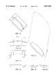
Referring to FIG. 1 through FIG. 7, the first preferred embodiment of the document stand is illustrated. The document stand is comprised of component 1 which serves as the base of the document stand and contains the effective sheet support mechanism within it. The sheet support mechanism is created through slot inner face 1a, slot outer face 1b, and slot lower face 1c. Slot inner face 1a and slot outer face 1b take on a similarly gently curved form in this embodiment. Slot lower face 1c is a flat, horizontal, continuous surface.
The bottom edge of the paper is flexed as required to fit into and conform to the bent shape of the device's slot. The placement of the paper will be such that the top tilts away from the viewer slightly. The paper will then be braced and held in place in a semi-rigid form that allows it to remain stable and hold its shape in this inclined position. The new shape and orientation of the inserted paper causes the central portion of the bottom edge of the paper to lie vertically beneath the level of the bottom corners of the paper. This lowest portion of the inserted paper will abut slot lower face 1c at a single point only, preferably at a location near the center of the bottom edge of the inserted paper.
There will be a tendency for the document stand to tilt backwards due to the cantilevering of the paper beyond the rear most point of contact of component 1 against the horizontal surface on which is sits. The weight of the material chosen for component 1 therefore must be sufficient to counterbalance this tendency. The texture of slot inner face 1a and slot outer face 1b must create sufficient friction to offset the tendency of the base of the inserted paper to slide up and out of the slot.
Referring to FIG. 8 through FIG. 14, the second preferred embodiment of the document stand is illustrated. The document stand is comprised of component 2 which serves as the base of the document stand and contains the effective sheet support mechanism within it. The sheet support mechanism is created through slot inner face 2a, slot outer face 2b, and slot lower face 2c. Slot inner face 2a and slot outer face 2b take on a similarly gently curved form in this embodiment. Slot lower face 1c is a continuous, vertically concave surface, deeper in the center than the ends. The bottom edge of the paper is flexed as required to fit into and conform to the bent shape of the device's slot. The placement of the paper will be such that the top tilts away from the viewer slightly. The paper will then be braced and held in place in a semi-rigid form that allows it to remain stable and hold its shape in this inclined position. The new shape and orientation of the inserted paper causes the central portion of the bottom edge of the paper to lie vertically beneath the level of the bottom corners of the paper. The vertically concave shape of slot lower face 2c follows the depth of the bottom edge of the inserted paper. This bottom edge of the inserted paper will abut slot lower face 2c continuously along its length. The top surface of component 2 is curved in this embodiment.
There will be a tendency for the document stand to tilt backwards due to the cantilevering of the paper beyond the rear most point of contact of component 2 against the horizontal surface on which it sits. The weight of the material chosen for component 2 therefore must be sufficient to counterbalance this tendency. The texture of slot inner face 2a and slot outer face 2b must create sufficient friction to offset the tendency of the base of the inserted paper to slide up and out of the slot.
Referring to FIG. 15 through FIG. 21, the third preferred embodiment of the document stand is illustrated. The document stand is comprised of top-front component 3, top-rear component 4 and two base components 5. The sheet support mechanism is created through slot inner face 3a, slot outer face 4a, and slot lower face 5a. Slot inner face 3a and slot outer face 4a take on a similarly gently curved form in this embodiment. Slot lower face 5a takes the form of two separate supports on either side of a central portion of the slot. The central portion of the slot has an open bottom.
The bottom edge of the paper is flexed as required to fit into and conform to the bent shape of the device's slot. The placement of the paper will be such that the top tilts away from the viewer slightly. The paper will then be braced and held in place in a semi-rigid form that allows it to remain stable and hold its shape in this inclined position. The new shape and orientation of the inserted paper causes the central portion of the bottom edge of the paper to lie vertically beneath the level of the paper. This bottom edge of the inserted paper will abut slot lower face 5a at two points, one on either side of the center. This effectively creates a two point support for the inserted paper from which the center portion of the lower edge of the paper may hang freely. The two base components 5 serve to attach top-front component 3 to top-rear component 4, and to create slot lower face 5a while raising it sufficiently to allow the center of the bottom edge of the inserted paper to hang freely.
There will be a tendency for the document stand to tilt backwards due to the cantilevering of the paper beyond the rear most point of contact of base components 5 against the horizontal surface on which they sit. The weight of the materials chosen for all components therefore must be sufficient to counterbalance this tendency. The texture of slot inner face 3a and slot outer face 4a must create sufficient friction to offset the tendency of the base of the inserted paper to slide up and out of the slot.
Referring to FIG. 22 through FIG. 28, the fourth preferred embodiment of the document stand is illustrated. The document stand is comprised of top-front component 6, top-rear component 7 and base component 8. The sheet support mechanism is created through slot inner face 6a, slot outer face 7a, and slot lower face 8a. Slot inner face 6a and slot outer face 7a take on slightly different faceted forms in this embodiment. Though base component 8 is shown as a single element, slot lower face 8a functions as two separate supports on either side of a central portion of the slot. The central portion of the slot has an open bottom.
The bottom edge of the paper is flexed as required to fit into and conform to the bent shape of the device's slot. The placement of the paper will be such that the top tilts away from the viewer slightly. The paper will then be braced and held in place in a semi-rigid form that allows it to remain stable and hold its shape in this inclined position. The new shape and orientation of the inserted paper causes the central portion of the bottom edge of the paper to lie vertically beneath the level of the bottom corners of the paper. This bottom edge of the inserted paper will abut slot lower face 8a at two points, one on either side of the center. This effectively creates a two point support for the inserted paper from which the center portion of the lower edge of the paper may hang freely. The base component 8 serves to attach top-front component 6 to top-rear component 7, and to create slot lower face 8a while raising it sufficiently to allow the center of the bottom edge of the inserted paper to hang freely.
There will be a tendency for the document stand to tilt backwards due to the cantilevering of the paper beyond the rear most point of contact of base component 8 against the horizontal surface on which it sits. The weight of the materials chosen for all components therefore must be sufficient to counterbalance this tendency. The texture of slot inner face 6a and slot outer face 7a must create sufficient friction to offset the tendency of the base of the inserted paper to slide up and out of the slot.
Referring to FIG. 29 through FIG. 35, the fifth preferred embodiment of the document stand is illustrated. The document stand is comprised of top-front component 9, top-rear component 10 and two base components 11. The sheet support mechanism is created through slot inner face 9a, slot outer face 10a, and slot lower face 11a. Slot inner face 9a and slot outer face 10a take on similar faceted forms in this embodiment. Slot lower face 11a takes the form of two separate supports on either side of a central portion of the slot. The central portion of the slot has an open bottom.
The bottom edge of the paper is flexed as required to fit into and conform to the bent shape of the device's slot. The placement of the paper will be such that the top tilts away from the viewer slightly. The paper will then be braced and held in place in a semi-rigid form that allows it to remain stable and hold its shape in this inclined position. The new shape and orientation of the inserted paper causes the central portion of the bottom edge of the paper to lie vertically beneath the level of the bottom corners of the paper. This bottom edge of the inserted paper will abut slot lower face 11a at two points, one on either side of the center. This effectively creates a two point support for the inserted paper from which the center portion of the lower edge of the paper may hang freely. The base components 11 serve to attach top-front component 9 to top-rear component 10, and to create slot lower face 11a while raising it sufficiently to allow the center of the bottom edge of the inserted paper to hang freely.
The extension of the two base components 11 beyond the vertical plane of the rear most extent of the inclined paper counterbalances any tendency of the document stand to tilt backwards due to the cantilevering of the paper. The texture of slot inner face 9a and slot outer face 10a must create sufficient friction to offset the tendency of the base of the inserted paper to slide up and out of the slot.
Referring to FIG. 36 through FIG. 42, the sixth preferred embodiment of the document stand is illustrated. The document stand is comprised of three top-front pegs 12, four top-rear pegs 13 and base component 14. The sheet support mechanism is created through slot inner face 12a, slot outer face 13a, and slot lower face 14a. Slot inner face 12a and slot outer face 13a are created through a series of pegs which delineate a bent slot through their configuration in this embodiment. Slot lower face 14a is a flat, horizontal, continuous surface.
The bottom edge of the paper is flexed as required to fit into and conform to the bent shape of the device's slot. The placement of the paper will be such that the top tilts away from the viewer slightly. The paper will then be braced and held in place in a semi-rigid form that allows it to remain stable and hold its shape in this inclined position. The new shape and orientation of the inserted paper causes the central portion of the bottom edge of the paper to lie vertically beneath the level of the bottom corners of the paper. This lowest portion of the inserted paper will abut slot lower face 14a at a single point only, preferably at a location near the center of the bottom edge of the inserted paper.
There will be a tendency for the document stand to tilt backwards due to the cantilevering of the paper beyond the rear most point of contact of base component 14 against the horizontal surface on which it sits. The weight of the materials chosen for all components therefore must be sufficient to counterbalance this tendency. Alternately the underside of component 14 may anchored directly to the stable surface on which it sits. The texture of slot inner face 12a and slot outer face 13a must create sufficient friction to offset the tendency of the base of the inserted paper to slide up and out of the slot.
While there have been shown and described several preferred embodiments of the document stand, it is understood that changes in structure, materials, sizes, and shapes can be made by those skilled in the art without departing from the invention. The invention is defined in the following claims.
Claims (4)
1. A document stand to support single or multiple sheets of inserted paper (or other thin flexible sheet material) comprising:
a base for supporting the inserted paper in a substantially upright position, slightly concave and inclined from the vertical;
said base includes a curved or otherwise bent slot on an upper portion adapted to receive a bottom edge of the inserted paper;
said slot includes an inner slot face, an outer slot face and a lower slot face;
said slot includes effective points of contact to support the inserted paper in an inclined, curved and stable position;
the outer slot face consists of three or more effective points of contact which follow a roughly horizontal direction;
the inner slot face consists of three or more effective points of contact which follow a roughly horizontal direction;
the lower slot face consists of at least one and no more than two effective points of contact.
2. The stand as set forth in claim 1 wherein said one effective point of contact which lies along the lower slot face is located approximately along the vertical axis bisecting the center of the inserted paper.
3. The stand as set forth in claim 1 wherein said two effective points of contact which lie along the lower slot face are located on either side of the vertical axis bisecting the center of the inserted paper, wherein the bottom center portion of the inserted paper shall hang freely.
4. A document stand to support single or multiple sheets of inserted paper (or other thin flexible sheet material) comprising:
a base for supporting the inserted paper in a substantially upright position, slightly concave and inclined from the vertical;
said base includes a series of pegs protruding from the upper portion of the device;
said pegs are arranged such that they follow along the path of two separate arcs oriented in the same direction along an approximately horizontal plane;
said arcs are separated such that a narrow continuous band of space is created between them that can receive a bottom edge of the inserted paper;
said base includes one or more points of support for the inserted paper along the lower surface of this continuous band of space between the arcs;
said base includes three or more pegs which lie along each of the two arcs, and come into contact with and serve to brace the inserted paper, whereby the inserted paper shall be supported in an inclined, curved and stable position.
Priority Applications (1)
| Application Number | Priority Date | Filing Date | Title |
|---|---|---|---|
| US08/781,348 US5857654A (en) | 1997-01-21 | 1997-01-21 | Document stand |
Applications Claiming Priority (1)
| Application Number | Priority Date | Filing Date | Title |
|---|---|---|---|
| US08/781,348 US5857654A (en) | 1997-01-21 | 1997-01-21 | Document stand |
Publications (1)
| Publication Number | Publication Date |
|---|---|
| US5857654A true US5857654A (en) | 1999-01-12 |
Family
ID=25122434
Family Applications (1)
| Application Number | Title | Priority Date | Filing Date |
|---|---|---|---|
| US08/781,348 Expired - Fee Related US5857654A (en) | 1997-01-21 | 1997-01-21 | Document stand |
Country Status (1)
| Country | Link |
|---|---|
| US (1) | US5857654A (en) |
Cited By (39)
| Publication number | Priority date | Publication date | Assignee | Title |
|---|---|---|---|---|
| US6059249A (en) * | 1998-06-02 | 2000-05-09 | Scatterday; Mark A. | Device for holding pages |
| US6129323A (en) * | 1998-08-31 | 2000-10-10 | Daishin Kohsan Co., Ltd. | Sheet stand |
| US6267346B1 (en) * | 1996-04-25 | 2001-07-31 | Etienne Dill | Device for holding a paper sheet |
| USD451962S1 (en) | 2001-01-08 | 2001-12-11 | The Quill Company, Inc. | Desk-top pen and paper holder |
| US6349915B1 (en) | 2000-05-02 | 2002-02-26 | Steelcase Development Corporation | Document support |
| US6382745B1 (en) * | 2000-09-08 | 2002-05-07 | Avis V. Adkins | Laptop workstation |
| USD460295S1 (en) | 2001-05-10 | 2002-07-16 | Jeremy J. Fissell | Skate wheel display/holder |
| USD466556S1 (en) | 2002-02-05 | 2002-12-03 | Adstracts, Inc. | Note holder |
| US20020179781A1 (en) * | 1998-08-07 | 2002-12-05 | Work-Rite Ergonomic Accessories, Inc. | Computer keyboard and mouse support having moveable mouse extension |
| GB2379634A (en) * | 2001-05-10 | 2003-03-19 | Rachel Anne Jacobson | Greetings card support |
| US6565058B1 (en) | 2002-02-11 | 2003-05-20 | Adstracts, Inc. | Promotional note holding apparatus |
| US20030111583A1 (en) * | 2001-12-13 | 2003-06-19 | Santarpia Gaetano | Support for display cards depicting religious images |
| US6678977B1 (en) * | 2003-01-21 | 2004-01-20 | Alan Sherman | Document holder |
| US6729060B1 (en) | 2003-03-20 | 2004-05-04 | Carla Rietkerk | Corner fitting frame |
| US20050016939A1 (en) * | 2003-07-24 | 2005-01-27 | Eby David C. | Desktop filing system |
| US20050016037A1 (en) * | 2003-07-24 | 2005-01-27 | Eby David C. | Cascadable file jackets |
| US20050016940A1 (en) * | 2003-07-24 | 2005-01-27 | Eby David C. | Task trays |
| US6874736B1 (en) | 2000-07-28 | 2005-04-05 | Steelcase Development Corporation | Keyboard support |
| US6877707B1 (en) | 2000-05-02 | 2005-04-12 | Steelcase Development Corporation | Integrated keyboard platform and document support |
| US6889951B1 (en) * | 2004-02-02 | 2005-05-10 | Michael Peter Shields | Document holder |
| US20060053668A1 (en) * | 2004-09-16 | 2006-03-16 | Busam Edward P | Posterboard display stand |
| US7083155B1 (en) * | 2001-03-29 | 2006-08-01 | Loyce Smartt | Adjustable reading bookstand |
| USD548796S1 (en) | 2006-05-25 | 2007-08-14 | Braeside Displays/Braeside Plastics Corporation | Display device |
| US20090193659A1 (en) * | 2006-06-29 | 2009-08-06 | Dorco Co., Ltd | Shaver |
| US20100123066A1 (en) * | 2008-11-20 | 2010-05-20 | Xerox Corporation | Imaging And Recording Device Media Staging Support |
| USD648401S1 (en) * | 2010-01-28 | 2011-11-08 | Heads Up Puzzles LLC | Gaming platform |
| USRE43158E1 (en) * | 1996-04-25 | 2012-02-07 | Midland Innovations, Limited Liability Corporation | Device for holding a paper sheet |
| USD664603S1 (en) | 2011-09-23 | 2012-07-31 | Heads Up Puzzles LLC | Gaming platform with playing pieces |
| USD665810S1 (en) * | 2010-07-28 | 2012-08-21 | Openpeak, Inc. | Cover for tablet computer |
| GB2489235A (en) * | 2011-03-21 | 2012-09-26 | Augustus Martin Ltd | Stand for flexible display material. |
| US20130264413A1 (en) * | 2010-09-28 | 2013-10-10 | Sakase Adtech Co., Ltd. | Stratospheric stay facility |
| WO2015135602A1 (en) * | 2014-03-14 | 2015-09-17 | Sabine Schiller | Display system |
| WO2015142982A1 (en) * | 2014-03-19 | 2015-09-24 | Jackson Lesley | Document stand unit |
| WO2016077826A1 (en) * | 2014-11-14 | 2016-05-19 | The United States Playing Card Company | Card connector |
| EP3159736A1 (en) * | 2015-10-23 | 2017-04-26 | Samsung Display Co., Ltd. | Stand for curved display device |
| USD811099S1 (en) * | 2016-06-01 | 2018-02-27 | Marie-Claude Marchand | Base for supporting artwork |
| USD910749S1 (en) * | 2018-11-14 | 2021-02-16 | Herman Miller Limited | Display stand |
| USD946083S1 (en) * | 2021-09-22 | 2022-03-15 | Richard Blyth | Desktop holder |
| USD1049227S1 (en) * | 2022-12-22 | 2024-10-29 | Starbucks Corporation | Card stand |
Citations (5)
| Publication number | Priority date | Publication date | Assignee | Title |
|---|---|---|---|---|
| US1681586A (en) * | 1926-12-23 | 1928-08-21 | Joseph C Beck | Display-card holder |
| US3779504A (en) * | 1972-04-17 | 1973-12-18 | S Schwartz | Stand for menus and the like |
| US4125243A (en) * | 1977-03-28 | 1978-11-14 | Integral Design, Inc. | Sign holder |
| US5505421A (en) * | 1995-01-11 | 1996-04-09 | Acco U.S.A., Inc. | Portable paper sheet copyholder |
| US5775663A (en) * | 1996-07-25 | 1998-07-07 | Microplas, Inc. | Copy Stand |
-
1997
- 1997-01-21 US US08/781,348 patent/US5857654A/en not_active Expired - Fee Related
Patent Citations (5)
| Publication number | Priority date | Publication date | Assignee | Title |
|---|---|---|---|---|
| US1681586A (en) * | 1926-12-23 | 1928-08-21 | Joseph C Beck | Display-card holder |
| US3779504A (en) * | 1972-04-17 | 1973-12-18 | S Schwartz | Stand for menus and the like |
| US4125243A (en) * | 1977-03-28 | 1978-11-14 | Integral Design, Inc. | Sign holder |
| US5505421A (en) * | 1995-01-11 | 1996-04-09 | Acco U.S.A., Inc. | Portable paper sheet copyholder |
| US5775663A (en) * | 1996-07-25 | 1998-07-07 | Microplas, Inc. | Copy Stand |
Cited By (57)
| Publication number | Priority date | Publication date | Assignee | Title |
|---|---|---|---|---|
| US6267346B1 (en) * | 1996-04-25 | 2001-07-31 | Etienne Dill | Device for holding a paper sheet |
| USRE43158E1 (en) * | 1996-04-25 | 2012-02-07 | Midland Innovations, Limited Liability Corporation | Device for holding a paper sheet |
| US6059249A (en) * | 1998-06-02 | 2000-05-09 | Scatterday; Mark A. | Device for holding pages |
| US6749158B2 (en) * | 1998-08-07 | 2004-06-15 | Work-Rite Ergonomic Accessories, Inc. | Computer keyboard and mouse support having moveable mouse extension |
| US20020179781A1 (en) * | 1998-08-07 | 2002-12-05 | Work-Rite Ergonomic Accessories, Inc. | Computer keyboard and mouse support having moveable mouse extension |
| US6129323A (en) * | 1998-08-31 | 2000-10-10 | Daishin Kohsan Co., Ltd. | Sheet stand |
| US7044425B2 (en) | 2000-05-02 | 2006-05-16 | Steelcase Development Corporation | Integrated keyboard platform and document support |
| US6349915B1 (en) | 2000-05-02 | 2002-02-26 | Steelcase Development Corporation | Document support |
| US6877707B1 (en) | 2000-05-02 | 2005-04-12 | Steelcase Development Corporation | Integrated keyboard platform and document support |
| US6874736B1 (en) | 2000-07-28 | 2005-04-05 | Steelcase Development Corporation | Keyboard support |
| US6382745B1 (en) * | 2000-09-08 | 2002-05-07 | Avis V. Adkins | Laptop workstation |
| USD451962S1 (en) | 2001-01-08 | 2001-12-11 | The Quill Company, Inc. | Desk-top pen and paper holder |
| US7083155B1 (en) * | 2001-03-29 | 2006-08-01 | Loyce Smartt | Adjustable reading bookstand |
| GB2379634B (en) * | 2001-05-10 | 2005-06-22 | Rachel Anne Jacobson | Greetings card support |
| USD460295S1 (en) | 2001-05-10 | 2002-07-16 | Jeremy J. Fissell | Skate wheel display/holder |
| GB2379634A (en) * | 2001-05-10 | 2003-03-19 | Rachel Anne Jacobson | Greetings card support |
| US20030111583A1 (en) * | 2001-12-13 | 2003-06-19 | Santarpia Gaetano | Support for display cards depicting religious images |
| USD466556S1 (en) | 2002-02-05 | 2002-12-03 | Adstracts, Inc. | Note holder |
| US6565058B1 (en) | 2002-02-11 | 2003-05-20 | Adstracts, Inc. | Promotional note holding apparatus |
| US6678977B1 (en) * | 2003-01-21 | 2004-01-20 | Alan Sherman | Document holder |
| US6729060B1 (en) | 2003-03-20 | 2004-05-04 | Carla Rietkerk | Corner fitting frame |
| US20050016940A1 (en) * | 2003-07-24 | 2005-01-27 | Eby David C. | Task trays |
| US20050016037A1 (en) * | 2003-07-24 | 2005-01-27 | Eby David C. | Cascadable file jackets |
| US7152351B2 (en) | 2003-07-24 | 2006-12-26 | Rubbermaid Incorporated | Cascadable file jackets |
| US7328799B2 (en) | 2003-07-24 | 2008-02-12 | Rubbermaid Incorporated | Task trays |
| US20050016939A1 (en) * | 2003-07-24 | 2005-01-27 | Eby David C. | Desktop filing system |
| US6889951B1 (en) * | 2004-02-02 | 2005-05-10 | Michael Peter Shields | Document holder |
| US20060053668A1 (en) * | 2004-09-16 | 2006-03-16 | Busam Edward P | Posterboard display stand |
| USD548796S1 (en) | 2006-05-25 | 2007-08-14 | Braeside Displays/Braeside Plastics Corporation | Display device |
| US20090193659A1 (en) * | 2006-06-29 | 2009-08-06 | Dorco Co., Ltd | Shaver |
| US9604373B2 (en) * | 2006-06-29 | 2017-03-28 | Dorco Co., Ltd. | Shaver |
| US11724411B2 (en) | 2006-06-29 | 2023-08-15 | Dorco Co., Ltd. | Shaver |
| US11358293B2 (en) | 2006-06-29 | 2022-06-14 | Dorco Co., Ltd. | Shaver |
| US10661460B2 (en) | 2006-06-29 | 2020-05-26 | Dorco Co., Ltd. | Shaver |
| US10245739B2 (en) | 2006-06-29 | 2019-04-02 | Dorco Co., Ltd. | Shaver |
| US9902077B2 (en) | 2006-06-29 | 2018-02-27 | Dorco Co., Ltd. | Shaver |
| US20100123066A1 (en) * | 2008-11-20 | 2010-05-20 | Xerox Corporation | Imaging And Recording Device Media Staging Support |
| USD648401S1 (en) * | 2010-01-28 | 2011-11-08 | Heads Up Puzzles LLC | Gaming platform |
| USD665810S1 (en) * | 2010-07-28 | 2012-08-21 | Openpeak, Inc. | Cover for tablet computer |
| US20130264413A1 (en) * | 2010-09-28 | 2013-10-10 | Sakase Adtech Co., Ltd. | Stratospheric stay facility |
| US9193432B2 (en) * | 2010-09-28 | 2015-11-24 | Sakase Adtech Co., Ltd. | Stratospheric stay facility |
| GB2489235B (en) * | 2011-03-21 | 2013-03-13 | Augustus Martin Ltd | Stands for display material |
| GB2489235A (en) * | 2011-03-21 | 2012-09-26 | Augustus Martin Ltd | Stand for flexible display material. |
| USD664603S1 (en) | 2011-09-23 | 2012-07-31 | Heads Up Puzzles LLC | Gaming platform with playing pieces |
| WO2015135602A1 (en) * | 2014-03-14 | 2015-09-17 | Sabine Schiller | Display system |
| WO2015142982A1 (en) * | 2014-03-19 | 2015-09-24 | Jackson Lesley | Document stand unit |
| US10021969B2 (en) | 2014-03-19 | 2018-07-17 | Lesley JACKSON | Document stand unit |
| CN106999786A (en) * | 2014-11-14 | 2017-08-01 | 美国扑克牌公司 | Card connector |
| WO2016077826A1 (en) * | 2014-11-14 | 2016-05-19 | The United States Playing Card Company | Card connector |
| CN107025849A (en) * | 2015-10-23 | 2017-08-08 | 三星显示有限公司 | Display device |
| US10349535B2 (en) | 2015-10-23 | 2019-07-09 | Samsung Display Co., Ltd. | Display device |
| US10701814B2 (en) | 2015-10-23 | 2020-06-30 | Samsung Display Co., Ltd. | Display device |
| EP3159736A1 (en) * | 2015-10-23 | 2017-04-26 | Samsung Display Co., Ltd. | Stand for curved display device |
| USD811099S1 (en) * | 2016-06-01 | 2018-02-27 | Marie-Claude Marchand | Base for supporting artwork |
| USD910749S1 (en) * | 2018-11-14 | 2021-02-16 | Herman Miller Limited | Display stand |
| USD946083S1 (en) * | 2021-09-22 | 2022-03-15 | Richard Blyth | Desktop holder |
| USD1049227S1 (en) * | 2022-12-22 | 2024-10-29 | Starbucks Corporation | Card stand |
Similar Documents
| Publication | Publication Date | Title |
|---|---|---|
| US5857654A (en) | Document stand | |
| US5911398A (en) | Portable copyholder | |
| US5651525A (en) | Reading stand | |
| AU2014384763B2 (en) | Stand for a portable device with a graphic user interface display | |
| US4685647A (en) | Magnifying reading stand | |
| US7185869B2 (en) | Foldable book holder | |
| US6981682B2 (en) | Support device for displaying individual books or similar items | |
| US20030103328A1 (en) | Modular stand for laptop computer | |
| US5921521A (en) | Copy stand | |
| US20100243854A1 (en) | Presentation pad easel | |
| EP1089158A3 (en) | Notebook computer with ergonomic stand | |
| EP0595824A4 (en) | Computer work station | |
| US5080315A (en) | Work station organizer and copyholder | |
| US6109585A (en) | Computer copy holder and monitor riser stand | |
| US5624096A (en) | Book support apparatus | |
| EP0442893B1 (en) | Draft/copy holder | |
| US5769378A (en) | Computer monitor utility assembly | |
| US6116562A (en) | Portable magnifier stand | |
| WO2005090213A1 (en) | Holder for multiple documents | |
| JP2000187446A (en) | Supporting device for flat display | |
| US6527247B1 (en) | Article support stand | |
| US20240237817A1 (en) | Book stand | |
| US5441228A (en) | Document holding and display device | |
| US20100294177A1 (en) | Modular computer workstation system | |
| GB2212389A (en) | Display device |
Legal Events
| Date | Code | Title | Description |
|---|---|---|---|
| FPAY | Fee payment |
Year of fee payment: 4 |
|
| FPAY | Fee payment |
Year of fee payment: 8 |
|
| REMI | Maintenance fee reminder mailed | ||
| LAPS | Lapse for failure to pay maintenance fees | ||
| STCH | Information on status: patent discontinuation |
Free format text: PATENT EXPIRED DUE TO NONPAYMENT OF MAINTENANCE FEES UNDER 37 CFR 1.362 |
|
| FP | Lapsed due to failure to pay maintenance fee |
Effective date: 20110112 |