US5857602A - Bicycle/ski carrier - Google Patents
Bicycle/ski carrier Download PDFInfo
- Publication number
- US5857602A US5857602A US08/904,870 US90487097A US5857602A US 5857602 A US5857602 A US 5857602A US 90487097 A US90487097 A US 90487097A US 5857602 A US5857602 A US 5857602A
- Authority
- US
- United States
- Prior art keywords
- mounting block
- frame
- post
- carrier
- lever
- Prior art date
- Legal status (The legal status is an assumption and is not a legal conclusion. Google has not performed a legal analysis and makes no representation as to the accuracy of the status listed.)
- Expired - Fee Related
Links
- 230000000717 retained effect Effects 0.000 claims description 2
- 230000037431 insertion Effects 0.000 abstract 1
- 238000003780 insertion Methods 0.000 abstract 1
- 239000000969 carrier Substances 0.000 description 4
- 238000000034 method Methods 0.000 description 2
- 241001236644 Lavinia Species 0.000 description 1
- 229910000831 Steel Inorganic materials 0.000 description 1
- 230000001154 acute effect Effects 0.000 description 1
- 238000009434 installation Methods 0.000 description 1
- 239000002184 metal Substances 0.000 description 1
- 239000007787 solid Substances 0.000 description 1
- 239000010959 steel Substances 0.000 description 1
Images


Classifications
-
- B—PERFORMING OPERATIONS; TRANSPORTING
- B60—VEHICLES IN GENERAL
- B60R—VEHICLES, VEHICLE FITTINGS, OR VEHICLE PARTS, NOT OTHERWISE PROVIDED FOR
- B60R9/00—Supplementary fittings on vehicle exterior for carrying loads, e.g. luggage, sports gear or the like
- B60R9/06—Supplementary fittings on vehicle exterior for carrying loads, e.g. luggage, sports gear or the like at vehicle front or rear
-
- Y—GENERAL TAGGING OF NEW TECHNOLOGICAL DEVELOPMENTS; GENERAL TAGGING OF CROSS-SECTIONAL TECHNOLOGIES SPANNING OVER SEVERAL SECTIONS OF THE IPC; TECHNICAL SUBJECTS COVERED BY FORMER USPC CROSS-REFERENCE ART COLLECTIONS [XRACs] AND DIGESTS
- Y10—TECHNICAL SUBJECTS COVERED BY FORMER USPC
- Y10S—TECHNICAL SUBJECTS COVERED BY FORMER USPC CROSS-REFERENCE ART COLLECTIONS [XRACs] AND DIGESTS
- Y10S224/00—Package and article carriers
- Y10S224/924—Vehicle attached carrier for bicycle or motorcycle
-
- Y—GENERAL TAGGING OF NEW TECHNOLOGICAL DEVELOPMENTS; GENERAL TAGGING OF CROSS-SECTIONAL TECHNOLOGIES SPANNING OVER SEVERAL SECTIONS OF THE IPC; TECHNICAL SUBJECTS COVERED BY FORMER USPC CROSS-REFERENCE ART COLLECTIONS [XRACs] AND DIGESTS
- Y10—TECHNICAL SUBJECTS COVERED BY FORMER USPC
- Y10T—TECHNICAL SUBJECTS COVERED BY FORMER US CLASSIFICATION
- Y10T403/00—Joints and connections
- Y10T403/59—Manually releaseable latch type
- Y10T403/591—Manually releaseable latch type having operating mechanism
- Y10T403/595—Lever
Definitions
- This invention relates to a carrier for use on a vehicle, and in particular to a bicycle/ski carrier for use on an automobile.
- While the device described herein is primarily intended for carrying bicycles or skis, it will be appreciated that the device can be used to carry other articles such as wheelchairs.
- the carrier described herein is adapted to be detachably mounted on a standard trailer hitch. Carriers of this type are well known and described in detail in the patent literature. Examples of such carriers are found, for example in U.S. Pat. No. 3,796,333, issued to Kenneth W. Goldstein on Mar. 12, 1974; U.S. Pat. No. 4,381,069, issued to Steven C. Kreck on Apr. 26, 1983; U.S. Pat. No. 4,400,129, issued to Jack Eisenberg et al on Aug. 23, 1983; U.S. Pat. No. 4,412,635, issued to Franklin B.
- Carriers currently available in the marketplace and those described in the above-listed patents vary in terms of strength, complexity and ease of use. However, there is always room for improvement.
- a utility carrier for use on a vehicle e.g. a car or truck, should be strong and easily attached to or detached from the vehicle. If a carrier cannot be mounted on a trailer hitch and removed therefrom by an individual acting along, then the carrier is not user friendly.
- utility carriers should be as simple as possible, with few moving parts.
- An object of the present invention is to meet the above-defined requirements by providing a carrier which is structurally simple, and which is still strong, safe and easy to use by an individual.
- Another object of the invention is to provide a carrier, which can quickly and easily be installed or removed from a trailer hitch, and which is adapted to carry a variety of articles, including (but not limited to) bicycles and skis.
- the invention relates to a carrier for attachment to a vehicle trailer hitch comprising:
- mounting block means for connection to a trailer hitch, said mounting block means, including a front end and a rear end, and a transversely extending groove in said front end;
- post means having a top end for receiving brackets for securing an article to said post means, and a bottom end;
- frame means on the bottom end of said post means for connection to said frame means including a pair of spaced apart side plates, rod means interconnecting a front end of said side plates, rotatable sleeve means spaced apart from said rod means and extending between a rear end of said plates, whereby the frame can be slid over the mounting block means to a position in which said side plates straddle the mounting block means, and said rod enters the groove in the front end of the mounting block means;
- latch means for locking said frame means and consequently said post means on said mounting block means, said latch means including cam means on said sleeve means for rotation therewith between a release position and a mounting block means engaging position; in which said frame means s returned on said mounting block means;
- lever means connected to said cam means for rotating said cam plate means between the release position and the engaging position
- latch plate means on said frame means for pivotally supporting said lever means for rotation between the cam release position and the mounting block engaging position.
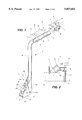
- FIG. 1 is an isometric view of a carrier in accordance with the present invention installed on a trailer hitch;
- FIG. 2 is a side view of a bracket used on the carrier of FIG. 1;
- FIG. 3 is an isometric view of the bottom end of the carrier of FIG. 1 installed on a mounting block;
- FIG. 4 is a top view of a latch plate used on the carrier of FIG. 1;
- FIG. 5 is a front view of the bottom end of the carrier of FIG. 1, with parts omitted.
- FIGS. 6 and 7 are longitudinal sectional views of the bottom end of the carrier of FIGS. 1 and 2 in a variety of positions during installation;
- FIGS. 8 and 9 are exploded isometric views of hitch adapters for use with the carrier of FIGS. 1 to 4.
- the carrier of the present invention includes an inverted L-shaped tubular post generally indicated at 1, the top, horizontal arm 2 of which carries a plurality of brackets 3 for connecting articles (not shown) such as bicycles or skis to the carrier.
- Each bracket 3 includes an L-shaped base plate 4 connected to the arm 2 by a U-bolt 5 and a cradle 6.
- An L-shaped top plate 7 is movably connected to the base plate 4 by a bolt 8 extending upwardly from the base plate 4 through the top plate 7, and a nut 9 for tightening the top plate 7 down against a bicycle bar or a pair of skis. Rubber pads 10 and 11 are provided on the base plate 4 and the top plate 7, respectively for protecting the finish on the article being carried.
- the assembly for mounting the carrier on a trailer hitch which is generally indicated at 12 is attached to the bottom end 13 of the vertical arm 14 of the post 1.
- the mounting assembly 12 is defined by a frame 15 including a pair of generally trapezoidal sides 16 welded to opposite sides of the bottom end 13 of the vertical arm 14 of the post 1.
- the outer or front ends of the sides 16 are interconnected by a rod 17 extending between such sides 16.
- a bolt 18 extends between the sides 16 near the rear ends thereof. In the mounted position (FIGS. 1, 3 and 7) the bolt 18 is located in a horizontal plane slightly above the rod 17.
- a nut 19 (FIG. 5) holds the bolt 18 in the frame 15.
- the mounting assembly 12 is intended for use with a mounting block 20 which is mounted on the trailing or outer end 21 of a trailer hitch, which in FIGS. 1, 3, 5 and 6 is merely a flat metal bar 22.
- the other end of the bar 22 is permanently connected to a vehicle (not shown).
- the mounting block 20 is a rectangular piece of steel with a transversely extending, generally U-shaped groove 24 in its outer or front end 25, and a bevelled rear end 26.
- the width of the block 20 is slightly less than the distance between the sides 16 of the frame 15 so that the frame 15 can freely slide over the block 20.
- a ball 27 is mounted on the block 20 for connecting a socket (not shown) when the hitch is used for towing a trailer or other vehicle.
- the frame 25 is releasably locked on the mounting block 20 and consequently on the trailer hitch using a latch mechanism, which includes a pair of cams 29, each of which is generally elliptical with a notch in one side of the bottom thereof defining a shoulder 30.
- the cams 29 are welded to a sleeve 31 which is rotatably mounted on the bolt 18 extending between the sides 16 of the frame 15.
- the sleeve 31 extends between the inner surfaces of the sides 16.
- the front of the bottom end 13 of the post 1 is bevelled.
- a rectangular notch 34 with a concave groove 35 (FIG. 5) at the top center thereof is provided in the front of such bottom end 13.
- the notch 34 and the groove 35 permit upward movement of the cams 29 during mounting of the carrier on a trailer hitch.
- a pin 37 extends between the curved top ends 38 of the cams 29, and is freely rotatable in such top ends.
- One end of a headless bolt 39 is threaded into the pin 37 and extends upwardly into the bifurcated bottom end 40 of a lever 41.
- the bolt 39 is secured to the lever 44 by a pin 43 extending through the flattened top end of the bolt 39 and one end of the lever 41.
- the lever 41 can be pulled upwardly with the cams 29 and rotated to turn the bolt 39 in the pin 43, i.e. to change the length of the portion of bolt 39 above the pin 43, and consequently the distance between the cams 29 and one end of the lever 41.
- the lever 41 is defined by a generally rectangular body 44 (FIG. 5) with a U-shaped notch 46 in one end for receiving the bolt 39.
- the pin 43 extends transversely of such one end of the lever 41 through the notch 46 and the top end of the bolt 39.
- the other end of the lever 41 defines a handle 47.
- a lock 48 (FIGS. 1 and 3), which is optional, is provided in the center of the body, the stem 50 (FIG. 5) of the lock extending out of the bottom of the body 44.
- a transversely extending C-shaped groove 51 (FIGS. 6 and 7) is provided in the bottom of the lever 41 for engaging a semicylindrical corner 52 of a latch plate 53 (FIG. 4), which is welded to the sides 16 of the frame 15.
- the corner 52 of the latch plate 53 defines a fulcrum or pivot point for the lever 41.
- the latch plate 53 includes a top rectangular arm 54 of L-shaped cross section which is welded on the sides 16 of the frame 15, and a pair of generally J-shaped arms 55 integral with and perpendicular to the top arm 54.
- a U-shaped notch 56 is provided in the top arm 54 forming a continuation of the slot between the arms 55 for receiving the top end of the bolt 39. While a lock is optional, if a lock is provided, the top arm 54 of the plate 53 includes a slot 57 for receiving the stem 50.
- the lever 41 is detached from the latch plates 53, and rests against curved bottom ends 58 of the J-shaped arms 55 of the latch plate 53. Actually, the arms 55 prevent the lever 39 failing through the frame with the cams 29.
- the gap between the rod 17 and the bolt 18 defines a slot for receiving the block 20.
- the first step in the mounting procedure is to tilt the carrier, so that the vertical arm 14 of the post 1 defines an acute angle with respect to the horizontal mounting block 20 (the lowermost position in FIG. 6), with the frame 1 straddling the mounting block 20 and the rear end of the hitch bar 22.
- the rod 17 is passed over the ball 27 and the front end 25 of the block 20 into the groove 24.
- the post 1 is then pivoted upwardly around the longitudinal axis of the rod 17 (counterclockwise in FIG. 6) until the arm 14 of the post 1 reaches the vertical position (FIGS. 1, 2 and 7).
- the cams 29 and the bolt 39 pass through the notch 34 and the groove 35, respectively in the bottom end of the post 1.
- the carrier can then be releasably locked in position using the latch mechanism.
- the lever 39 is pulled upwardly and the groove is aligned with the corner 51 of the latch plate 52.
- the lever 39 is then pivoted around the axis of the semicylindrical corner 51 from the open position (shown in solid lines in FIG. 7) to the closed position (shown in phantom outline in FIG. 7). If the lock is used, the pin 50 of the lock 48 enters the slot 57 and a key (not shown) is inserted in the top of the locked and turned to lock the lever 41 in the closed position.
- the latch mechanism is released by reversing this procedure, i.e. by lifting the front end of the lever 41 to unlatch the mechanism.
- the carrier can be used with a variety of trailer hitches.
- one such hitch is of the type including a square cross section socket 60 which is welded to a vehicle (not shown).
- a square cross section, tubular hitch bar 61 is slidable in the trailing, free end of the socket 60.
- Aligned holes 62 are provided in the socket 60 and the bar 61 for receiving an L-shaped locking pin 64.
- the pin 64 is retained in the holes 62 by a cotter pin 65, which is inserted into a hole 66 in the pin 64 after the latter has been passed through the aligned holes 62.
- a sleeve 68 on the bar 61 limits movement of the bar 61 into the socket 60.
- the mounting block 20 is attached to the top end of a tubular post 72.
- the post 72 is mounted on the bar 61 using a threaded rod 73, a washer 74 welded in the top end of the post 72, and nuts 75 on each end of the rod 73.
- the ball 27 is mounted on a tubular extension 77 at the bevelled, trailing end of the bar 61 by means of a bolt 78 extending upwardly through a hole 79 in the bar into a threaded bore (not shown) in the bottom of the ball 27.
- FIG. 9 Another hitch for use with the carrier of the present invention is illustrated in FIG. 9.
- the hitch of FIG. 9 includes a socket 60 for receiving a solid, square cross section hitch bar 80.
- the socket 60 and the hitch bar 80 are interconnected in the same manner as the hitch of FIG. 8, and accordingly wherever possible the same reference numerals have been used to identify the same or similar elements.
- the mounting block 20 and the ball 27 are attached to the square trailing end 81 of the bar 80 using a bolt 82 which extends upwardly through aligned holes 83 and 84 in the bar 80 and the block 20 into the threaded bore in the ball 27.
- the carrier described above is structurally simple and easy to install and detach from a tailer hitch.
Landscapes
- Engineering & Computer Science (AREA)
- Mechanical Engineering (AREA)
- Fittings On The Vehicle Exterior For Carrying Loads, And Devices For Holding Or Mounting Articles (AREA)
Abstract
Description
Claims (5)
Priority Applications (1)
| Application Number | Priority Date | Filing Date | Title |
|---|---|---|---|
| US08/904,870 US5857602A (en) | 1997-08-01 | 1997-08-01 | Bicycle/ski carrier |
Applications Claiming Priority (1)
| Application Number | Priority Date | Filing Date | Title |
|---|---|---|---|
| US08/904,870 US5857602A (en) | 1997-08-01 | 1997-08-01 | Bicycle/ski carrier |
Publications (1)
| Publication Number | Publication Date |
|---|---|
| US5857602A true US5857602A (en) | 1999-01-12 |
Family
ID=25419906
Family Applications (1)
| Application Number | Title | Priority Date | Filing Date |
|---|---|---|---|
| US08/904,870 Expired - Fee Related US5857602A (en) | 1997-08-01 | 1997-08-01 | Bicycle/ski carrier |
Country Status (1)
| Country | Link |
|---|---|
| US (1) | US5857602A (en) |
Cited By (13)
| Publication number | Priority date | Publication date | Assignee | Title |
|---|---|---|---|---|
| US6283349B1 (en) | 1998-12-09 | 2001-09-04 | Danik Industries Ltd. | Self-locking bicycle carrier |
| US6321962B1 (en) | 1998-12-09 | 2001-11-27 | Danik Industries Ltd. | Self-locking bicycle carrier |
| US6547116B2 (en) * | 2001-02-05 | 2003-04-15 | Evan R. Anderson | Bicycle car rack and work stand |
| US6623025B2 (en) | 2001-06-02 | 2003-09-23 | Cequent Towing Products, Inc. | Trailer hitch with trailer hitch accessory mounting assembly |
| US6732893B2 (en) | 1998-12-09 | 2004-05-11 | Danik Industries, Ltd. | Self-locking bicycle carrier |
| US20040256430A1 (en) * | 2003-06-23 | 2004-12-23 | Wang Chiu Kuei | Fastening device for bicycle rack |
| US6974147B1 (en) | 2003-10-06 | 2005-12-13 | Saris Cycling Group, Inc. | Internal tightening system for preventing relative movement between a pair of interconnected members |
| US20060180950A1 (en) * | 2005-02-09 | 2006-08-17 | Jordan Richard D | Apparatus for and method of forming concrete and transferring loads between concrete slabs |
| US20070138762A1 (en) * | 2005-12-19 | 2007-06-21 | Dietz Dan L | Anti-vibration and stabilizer trailer hitch apparatus and system |
| USD566029S1 (en) | 2005-07-27 | 2008-04-08 | Meco Corporation | Wheel chock |
| US20080101899A1 (en) * | 2006-10-27 | 2008-05-01 | Stacy Evan Slonecker | Refuse or recycling cart lifting and transporting device |
| US20090078732A1 (en) * | 2007-09-25 | 2009-03-26 | John Rodney Allsop | Carrying device mountable on a tow-ball |
| EP2379371A4 (en) * | 2009-01-20 | 2012-06-13 | Double You Four | Bicycle holder |
Citations (10)
| Publication number | Priority date | Publication date | Assignee | Title |
|---|---|---|---|---|
| US3796333A (en) * | 1971-08-13 | 1974-03-12 | K Goldstein | Detachable carrier for vehicles |
| US4381069A (en) * | 1980-09-22 | 1983-04-26 | Kreck Steven C | Outboard motor carrier for motor vehicle |
| US4400129A (en) * | 1981-06-24 | 1983-08-23 | Jack Eisenberg | Wheelchair carrier and loading device |
| US4412635A (en) * | 1982-08-12 | 1983-11-01 | Bateman Franklin B | Trailer hitch-mounted utility carrier for vehicles |
| US5190195A (en) * | 1991-03-15 | 1993-03-02 | Reese Products | Hitch mounted bicycle rack |
| US5303857A (en) * | 1992-09-10 | 1994-04-19 | Erling Peter Justesen | Swing-down bicycle carrier for vehicles |
| US5330084A (en) * | 1993-04-12 | 1994-07-19 | Peters Mark R | Bicycle rack apparatus |
| US5449101A (en) * | 1993-10-27 | 1995-09-12 | Mascotech Accessories, Inc. | Hitch rack for an automotive vehicle |
| US5529231A (en) * | 1994-06-10 | 1996-06-25 | Red Rock Industries | Adjustable car carrier |
| US5549230A (en) * | 1990-12-27 | 1996-08-27 | Palmen; Isedore D. M. H. | Luggage carrier for motorcars |
-
1997
- 1997-08-01 US US08/904,870 patent/US5857602A/en not_active Expired - Fee Related
Patent Citations (10)
| Publication number | Priority date | Publication date | Assignee | Title |
|---|---|---|---|---|
| US3796333A (en) * | 1971-08-13 | 1974-03-12 | K Goldstein | Detachable carrier for vehicles |
| US4381069A (en) * | 1980-09-22 | 1983-04-26 | Kreck Steven C | Outboard motor carrier for motor vehicle |
| US4400129A (en) * | 1981-06-24 | 1983-08-23 | Jack Eisenberg | Wheelchair carrier and loading device |
| US4412635A (en) * | 1982-08-12 | 1983-11-01 | Bateman Franklin B | Trailer hitch-mounted utility carrier for vehicles |
| US5549230A (en) * | 1990-12-27 | 1996-08-27 | Palmen; Isedore D. M. H. | Luggage carrier for motorcars |
| US5190195A (en) * | 1991-03-15 | 1993-03-02 | Reese Products | Hitch mounted bicycle rack |
| US5303857A (en) * | 1992-09-10 | 1994-04-19 | Erling Peter Justesen | Swing-down bicycle carrier for vehicles |
| US5330084A (en) * | 1993-04-12 | 1994-07-19 | Peters Mark R | Bicycle rack apparatus |
| US5449101A (en) * | 1993-10-27 | 1995-09-12 | Mascotech Accessories, Inc. | Hitch rack for an automotive vehicle |
| US5529231A (en) * | 1994-06-10 | 1996-06-25 | Red Rock Industries | Adjustable car carrier |
Cited By (19)
| Publication number | Priority date | Publication date | Assignee | Title |
|---|---|---|---|---|
| US6283349B1 (en) | 1998-12-09 | 2001-09-04 | Danik Industries Ltd. | Self-locking bicycle carrier |
| US6321962B1 (en) | 1998-12-09 | 2001-11-27 | Danik Industries Ltd. | Self-locking bicycle carrier |
| US6732893B2 (en) | 1998-12-09 | 2004-05-11 | Danik Industries, Ltd. | Self-locking bicycle carrier |
| US6547116B2 (en) * | 2001-02-05 | 2003-04-15 | Evan R. Anderson | Bicycle car rack and work stand |
| US20030102343A1 (en) * | 2001-02-05 | 2003-06-05 | Anderson Evan R. | Bicycle car rack and work stand |
| US6854630B2 (en) | 2001-02-05 | 2005-02-15 | Evan R. Anderson | Bicycle car rack and work stand |
| US6623025B2 (en) | 2001-06-02 | 2003-09-23 | Cequent Towing Products, Inc. | Trailer hitch with trailer hitch accessory mounting assembly |
| US20040256430A1 (en) * | 2003-06-23 | 2004-12-23 | Wang Chiu Kuei | Fastening device for bicycle rack |
| US6974147B1 (en) | 2003-10-06 | 2005-12-13 | Saris Cycling Group, Inc. | Internal tightening system for preventing relative movement between a pair of interconnected members |
| US20060180950A1 (en) * | 2005-02-09 | 2006-08-17 | Jordan Richard D | Apparatus for and method of forming concrete and transferring loads between concrete slabs |
| USD566029S1 (en) | 2005-07-27 | 2008-04-08 | Meco Corporation | Wheel chock |
| USD583743S1 (en) | 2005-07-27 | 2008-12-30 | Meco Corporation | Wheel chock |
| USD583745S1 (en) | 2005-07-27 | 2008-12-30 | Meco Corporation | Wheel chock baseplate |
| USD583744S1 (en) | 2005-07-27 | 2008-12-30 | Meco Corporation | Wheel chock baseplate |
| US20070138762A1 (en) * | 2005-12-19 | 2007-06-21 | Dietz Dan L | Anti-vibration and stabilizer trailer hitch apparatus and system |
| US20080101899A1 (en) * | 2006-10-27 | 2008-05-01 | Stacy Evan Slonecker | Refuse or recycling cart lifting and transporting device |
| US20090078732A1 (en) * | 2007-09-25 | 2009-03-26 | John Rodney Allsop | Carrying device mountable on a tow-ball |
| US8191746B2 (en) | 2007-09-25 | 2012-06-05 | John Rodney Allsop | Carrying device mountable on a tow-ball |
| EP2379371A4 (en) * | 2009-01-20 | 2012-06-13 | Double You Four | Bicycle holder |
Similar Documents
| Publication | Publication Date | Title |
|---|---|---|
| US8371603B2 (en) | Maximum security/maximum versatility ball mount assembly | |
| US8840130B2 (en) | Maximum security/maximum versatility ball mount assembly | |
| US5857602A (en) | Bicycle/ski carrier | |
| US8226107B2 (en) | Maximum security/maximum versatility ball mount assembly | |
| US5465991A (en) | Weight distributing hitch | |
| US5004133A (en) | Detachable article carrier assembly | |
| US5375867A (en) | Weight distributing hitch | |
| US7967311B2 (en) | Multi position step | |
| US5285937A (en) | Cycle rack | |
| US5816757A (en) | Utility trailer retaining bar hold down clamp | |
| US6969085B2 (en) | Safety hold down device and hitch guide for trailer decoupling prevention | |
| US9630463B2 (en) | Maximum security/maximum versatility ball mount assembly | |
| US5893575A (en) | Hitch assembly | |
| US7704034B1 (en) | Motorcycle towing device and method | |
| US10336146B2 (en) | Removable securing chain attachment assembly | |
| US7506885B2 (en) | Load-leveling, weight-distributing hitch system | |
| US20040075240A1 (en) | Hitch locking mechanism | |
| CA1299214C (en) | Lift unit for weight distributing trailer hitch | |
| US6637765B2 (en) | Towing safety device | |
| US7081197B1 (en) | Step apparatus | |
| US3923220A (en) | Motor bike stabilizer | |
| US7431319B2 (en) | Hitch locking mechanism | |
| US6623025B2 (en) | Trailer hitch with trailer hitch accessory mounting assembly | |
| US4863185A (en) | Universal trailer hitch apparatus | |
| US5027991A (en) | Trailer tire rack |
Legal Events
| Date | Code | Title | Description |
|---|---|---|---|
| AS | Assignment |
Owner name: TRANSFO-RAKZS INC., CANADA Free format text: ASSIGNMENT OF ASSIGNORS INTEREST;ASSIGNOR:DEPOT, GERMAIN;REEL/FRAME:008734/0382 Effective date: 19970716 |
|
| AS | Assignment |
Owner name: SPORTRACK INTERNATIONAL INC., A CORPORATION OF CAN Free format text: ASSIGNMENT OF ASSIGNORS INTEREST;ASSIGNOR:BELISLE, PIERRE, ON BEHALF OF TRANSFO-RAKZS INC.;REEL/FRAME:010216/0099 Effective date: 19980207 |
|
| FPAY | Fee payment |
Year of fee payment: 4 |
|
| AS | Assignment |
Owner name: SPORTRACK ACCESSORIES INC., CANADA Free format text: CHANGE OF NAME;ASSIGNOR:SPORTRACK INTERNATIONAL INC.;REEL/FRAME:013897/0927 Effective date: 19991018 |
|
| AS | Assignment |
Owner name: GENERAL ELECTRIC CAPITAL, NEW YORK Free format text: SECURITY INTEREST;ASSIGNOR:SPORTRACK ACCESSORIES INC.;REEL/FRAME:014033/0971 Effective date: 20030415 |
|
| REMI | Maintenance fee reminder mailed | ||
| LAPS | Lapse for failure to pay maintenance fees | ||
| STCH | Information on status: patent discontinuation |
Free format text: PATENT EXPIRED DUE TO NONPAYMENT OF MAINTENANCE FEES UNDER 37 CFR 1.362 |
|
| FP | Expired due to failure to pay maintenance fee |
Effective date: 20070112 |
|
| AS | Assignment |
Owner name: THULE AB, SWEDEN Free format text: ASSIGNMENT OF ASSIGNORS INTEREST;ASSIGNOR:SPORTRACK, LLC;REEL/FRAME:021185/0978 Effective date: 20060906 |