US584939A - Tht nohris peters co - Google Patents
Tht nohris peters co Download PDFInfo
- Publication number
- US584939A US584939A US584939DA US584939A US 584939 A US584939 A US 584939A US 584939D A US584939D A US 584939DA US 584939 A US584939 A US 584939A
- Authority
- US
- United States
- Prior art keywords
- globe
- thumb
- bar
- piece
- lamp
- Prior art date
- Legal status (The legal status is an assumption and is not a legal conclusion. Google has not performed a legal analysis and makes no representation as to the accuracy of the status listed.)
- Expired - Lifetime
Links
- 241001465382 Physalis alkekengi Species 0.000 description 4
- 238000010276 construction Methods 0.000 description 2
- 230000000284 resting effect Effects 0.000 description 2
- 238000005452 bending Methods 0.000 description 1
- 238000002485 combustion reaction Methods 0.000 description 1
- 239000002184 metal Substances 0.000 description 1
- 238000004326 stimulated echo acquisition mode for imaging Methods 0.000 description 1
- 210000003813 thumb Anatomy 0.000 description 1
- 238000009966 trimming Methods 0.000 description 1
Images
Classifications
-
- F—MECHANICAL ENGINEERING; LIGHTING; HEATING; WEAPONS; BLASTING
- F21—LIGHTING
- F21L—LIGHTING DEVICES OR SYSTEMS THEREOF, BEING PORTABLE OR SPECIALLY ADAPTED FOR TRANSPORTATION
- F21L19/00—Lanterns, e.g. hurricane lamps or candle lamps
- F21L19/003—Fastening or lifting of the lamp glass
Definitions
- This invention relates to that class of lamps and lanterns which are provided with a tubular frame in which the globe is supported on a vertically-movable plate or holder, so that this plate or holder can be raised to lift the globe from the burner for giving access to the latter .for lighting, trimming the wick, and other purposes.
- the object of this invention is to provide the lamp or lantern with a simple and convenient device for raising the globe and looking it in an elevated position.
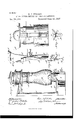
- Figure 1 is a side elevation of a tubular lamp provided with my improvements.
- Fig. 2 is a fragmentary front elevation of the lower portion of the lamp, on an enlarged scale, showing the globe and its supporting-plate resting on the burner.
- Fig. 3 is a horizontal section in line 3 3, Fig. 2.
- Fig. 4 is a fragmentary vertical section in line 4 4, Fig. 2, but showing the globe and its supporting-plate locked in an elevated position.
- Fig. 5 is a fragmentary perspective View of the spring-catch and connecting parts of the globe-elevatin g device in an elevated position.
- A represents the oil-pot; B, the air-chamber secured'on the front portion'of the oilpot; C, the burner resting on this air-chamber; D the vertical portion, D the upper horizontal portion, and D the lower horizontal portion, of the air-tube, and E the lamp-top containing the air injecting or supply devices and the chimney F for the escape of the products of combustion.
- G represents the globe-supporting plate, which rests normally on the shoulder of the burner, and H the globe, which is held down on the globe-supporting plate by a spring in the lamp-top (not shown in the drawings) and acting upon a collar I, which bears upon the top of the globe.
- the lamp shown in the drawings and herein described is of well-known construction and of the kind designed to be arranged against a wall and usually designated as side lamps; but I do not intend to limit myself to the specific features of this style of lamp, as my invention is also applicable to lamps and lanterns of different constructions.
- K represents an upright bar which'is arranged on the front side of the lower or base portion of the lamp structure and which is connected at its upper end with the plate or holder on which the globe rests.
- L represents a vertical guideway which is secured to the lower front portion of the lamp structure and in which the bar K is arranged so as to be capable of vertical movement therein.
- This guideway is secured, as shown, to the front portion of the oil-pot and is provided at its front side with inwardly-projecting upright side flanges Z,which are separated by an open space.
- M is a catch which is arranged on the front side of the bar K and which consists of a short upright bar m, yieldingly connected at its lower end with the lower portion of the bar K and a thumb-piece n, which projects forwardly from the upper end of the bar m through the space between the upright side flanges l of the guideway.
- the upright bar m and the thumb-piece n are formed in one piece with the bar K by bending a bar of elastic metal to the desired form.
- the thumb-piece n is formed in its side edges with notches 0, so arranged and of such size that when the catch is pressed back, as shown in Figs. 1, 2, and 3, the upright part m of the catch will stand behind the side flanges Z of the guideway and the notches 0 of the thumb-piece will coincide with these side flanges, thus allowing the bar K and the catch M, attached thereto, to be moved up and down in the guideway.
- the thumb-piece springs forwardly, thereby bringing that portion of the thumb-piece which lies in. rear of the notches above the side flanges, as shown in Figs.
- a fixed thumb-piece P is secured to the front portion of the lamp or lantern structure above the guideway.
- This stationary thumb-piece preferably straddles the upright bar K.
- the movable thumb-piece a is preferably reinforced by an angle-brace p, which is secured with its upper end to the under side of the forwardly-projectin g part of the thumbpieee and with its lower end to the front side of the upright part of the thumb-piece.
- the combination with a lamp or lantern having a vertically-movable globe-holder, of an upright guideway secured to the lower portion of the lamp or lantern frame and having on its front side upright side flanges, an upright bar capable of sliding vertically in said guideway and attached at its upper end to said globe-holder, and a yielding catch attached to the front side of said bar and arranged in the space between said side flanges, said catch being adapted to engage over said guideway and support the globe-holder when the latter has been elevated, substantially as set forth. 2.
- a lamp or lantern having a vertically-movable globe-holder, of an upright guideway secu red to the lower portion of the lamp or lantern, an upright bar capable of sliding vertically in said guideway and attached at its upper end to said globe-holder, a yielding catch attached to the front side of said bar and provided with a forward]y-projecting thumb-piece by which said upright bar can be pulled upwardly and which engages over said guideway and supports the globe-holder when the latter has been elevated, and a stationary thumb-piece secured to the base portion of the lamp or lantern and straddling said upright bar above said guideway, substantially as set forth.
- a lamp or lantern having a vertically-movable globe-holder, of an upright guideway secured to the lamp or lantern frame and having upright side flanges, an upright bar guided in said guideway behind said side flanges and connected with said globe-holder, and a thumb-piece attached to said upright bar and adapted to rest on said side flanges and having side notches adapted to clear the side flanges when the thumb-pieee is pressed back, substantially as set forth.
- ⁇ Vitncsses FRANK O. OnowELL, Em'nsr R. CHAMBERLAIN.
Landscapes
- Engineering & Computer Science (AREA)
- General Engineering & Computer Science (AREA)
- Non-Portable Lighting Devices Or Systems Thereof (AREA)
Description
(No Model B. J. KELLEY. GLOBE LIPTING DEVICE FOR LAMPS OR LANTEHNS.
No. 584,939. Patented June 22, 1897.
7/?25165565 1 V/ Ja/ezzZ or: 4
NITED STATES PATENT FFICE.
RICHARD J. KELLEY, OF SYRACUSE, NEW YORK, ASSIGNOR TO THE STEAM GAUGE AND LANTERN COMPANY, OF SAME PLACE, AND THE R. E. DIETZ COMPANY, OF NEW" YORK, N. Y.
GLOBE-LIFTING DEVICE FOR LAMPS OR LANTERNS.
SPECIFICATION forming part of Letters Patent No. 584,939, dated June 22, 1897. Application filed June 23, 1896. Serial No. 596,601. (No model.)
To all whom it may concern.-
Be it known that I, RICHARD J. KELLEY, a citizen of the United States, residing at Syracuse, in the county of Onondaga, in the State of New York, have invented a new and useful Improvement in Globe-Lifting Devices for Lamps and Lanterns, of which the following is a specification.
This invention relates to that class of lamps and lanterns which are provided with a tubular frame in which the globe is supported on a vertically-movable plate or holder, so that this plate or holder can be raised to lift the globe from the burner for giving access to the latter .for lighting, trimming the wick, and other purposes.
The object of this invention is to provide the lamp or lantern with a simple and convenient device for raising the globe and looking it in an elevated position.
In the accompanying drawings, Figure 1 is a side elevation of a tubular lamp provided with my improvements. Fig. 2 is a fragmentary front elevation of the lower portion of the lamp, on an enlarged scale, showing the globe and its supporting-plate resting on the burner. Fig. 3 is a horizontal section in line 3 3, Fig. 2. Fig. 4 is a fragmentary vertical section in line 4 4, Fig. 2, but showing the globe and its supporting-plate locked in an elevated position. Fig. 5 is a fragmentary perspective View of the spring-catch and connecting parts of the globe-elevatin g device in an elevated position.
Like letters of reference refer to like parts in the several figures.
A represents the oil-pot; B, the air-chamber secured'on the front portion'of the oilpot; C, the burner resting on this air-chamber; D the vertical portion, D the upper horizontal portion, and D the lower horizontal portion, of the air-tube, and E the lamp-top containing the air injecting or supply devices and the chimney F for the escape of the products of combustion.
G represents the globe-supporting plate, which rests normally on the shoulder of the burner, and H the globe, which is held down on the globe-supporting plate by a spring in the lamp-top (not shown in the drawings) and acting upon a collar I, which bears upon the top of the globe.
The lamp shown in the drawings and herein described is of well-known construction and of the kind designed to be arranged against a wall and usually designated as side lamps; but I do not intend to limit myself to the specific features of this style of lamp, as my invention is also applicable to lamps and lanterns of different constructions.
K represents an upright bar which'is arranged on the front side of the lower or base portion of the lamp structure and which is connected at its upper end with the plate or holder on which the globe rests.
L represents a vertical guideway which is secured to the lower front portion of the lamp structure and in which the bar K is arranged so as to be capable of vertical movement therein. This guideway is secured, as shown, to the front portion of the oil-pot and is provided at its front side with inwardly-projecting upright side flanges Z,which are separated by an open space.
M is a catch which is arranged on the front side of the bar K and which consists of a short upright bar m, yieldingly connected at its lower end with the lower portion of the bar K and a thumb-piece n, which projects forwardly from the upper end of the bar m through the space between the upright side flanges l of the guideway. As shown in the drawings, the upright bar m and the thumb-piece n are formed in one piece with the bar K by bending a bar of elastic metal to the desired form.
The thumb-piece n is formed in its side edges with notches 0, so arranged and of such size that when the catch is pressed back, as shown in Figs. 1, 2, and 3, the upright part m of the catch will stand behind the side flanges Z of the guideway and the notches 0 of the thumb-piece will coincide with these side flanges, thus allowing the bar K and the catch M, attached thereto, to be moved up and down in the guideway. When the bar K and catch M have been raised to such a position that the thumb-piece n clears the upper ends of the side flanges Z, the thumb-piece springs forwardly, thereby bringing that portion of the thumb-piece which lies in. rear of the notches above the side flanges, as shown in Figs. 4 and 5. In this position of the thumb piece the rear portion of the latter behind the notches rests upon the upper ends of the side flanges and supports the bar K and the globeplate and globe at that elevation at which the globe-plate is sulfieiently elevated above the burner to give access to the latter. Upon pressing the thumb-piece back, so as to bring its notches in line with the side flanges, thd bar K and the globe-holder are released ane the bar K, globe-holder, and globe are lowered by the weight of these parts, aided by the pressure of the spring acting upon the globe when such a spring is present in the lamp or lantern.
In order to facilitate the manipulation of the thumb-piece on the vertically-movable bar, a fixed thumb-piece P is secured to the front portion of the lamp or lantern structure above the guideway. This stationary thumb-piece preferably straddles the upright bar K. By grasping both thumb-pieces the lower movable thumb-piece is readily manipulated.
The movable thumb-piece a is preferably reinforced by an angle-brace p, which is secured with its upper end to the under side of the forwardly-projectin g part of the thumbpieee and with its lower end to the front side of the upright part of the thumb-piece.
I claim as my invention 1. The combination with a lamp or lantern having a vertically-movable globe-holder, of an upright guideway secured to the lower portion of the lamp or lantern frame and having on its front side upright side flanges, an upright bar capable of sliding vertically in said guideway and attached at its upper end to said globe-holder, and a yielding catch attached to the front side of said bar and arranged in the space between said side flanges, said catch being adapted to engage over said guideway and support the globe-holder when the latter has been elevated, substantially as set forth. 2. The combination with a lamp or lantern having a vertically-movable globe-holder, of an upright guideway secu red to the lower portion of the lamp or lantern, an upright bar capable of sliding vertically in said guideway and attached at its upper end to said globe-holder, a yielding catch attached to the front side of said bar and provided with a forward]y-projecting thumb-piece by which said upright bar can be pulled upwardly and which engages over said guideway and supports the globe-holder when the latter has been elevated, and a stationary thumb-piece secured to the base portion of the lamp or lantern and straddling said upright bar above said guideway, substantially as set forth.
The combination with a lamp or lantern having a vertically-movable globe-holder, of an upright guideway secured to the lamp or lantern frame and having upright side flanges, an upright bar guided in said guideway behind said side flanges and connected with said globe-holder, and a thumb-piece attached to said upright bar and adapted to rest on said side flanges and having side notches adapted to clear the side flanges when the thumb-pieee is pressed back, substantially as set forth.
Vitness my hand this 19th day of June, 1896.
RICHARD J. KELLEY.
\Vitncsses: FRANK O. OnowELL, Em'nsr R. CHAMBERLAIN.
Publications (1)
| Publication Number | Publication Date |
|---|---|
| US584939A true US584939A (en) | 1897-06-22 |
Family
ID=2653609
Family Applications (1)
| Application Number | Title | Priority Date | Filing Date |
|---|---|---|---|
| US584939D Expired - Lifetime US584939A (en) | Tht nohris peters co |
Country Status (1)
| Country | Link |
|---|---|
| US (1) | US584939A (en) |
-
0
- US US584939D patent/US584939A/en not_active Expired - Lifetime
Similar Documents
| Publication | Publication Date | Title |
|---|---|---|
| US391240A (en) | Blias c | |
| US191888A (en) | Improvement in lamp-refractors | |
| US204608A (en) | Improvement in lamps | |
| US529017A (en) | Charles bergener | |
| US618804A (en) | Street-lamp | |
| US799977A (en) | Lantern. | |
| US1068026A (en) | Tubular lantern. | |
| US572895A (en) | sinks | |
| US353573A (en) | Lantern | |
| US192347A (en) | Improvement in combined lamp and gas lighter | |
| US458341A (en) | Lantern | |
| US507706A (en) | Charles bergener | |
| US306343A (en) | Lantern | |
| US409506A (en) | Lantern | |
| US394025A (en) | Lantern | |
| US1067968A (en) | Tubular lantern. | |
| US401490A (en) | Elias g | |
| US310464A (en) | Signal-lantern | |
| US649529A (en) | Tubular lantern. | |
| US414917A (en) | Candlestick | |
| US624933A (en) | Frank iieyard | |
| US387970A (en) | Tubular lantern | |
| US401116A (en) | Tubular lantern | |
| US596780A (en) | Lamp or lantern | |
| US99442A (en) | Improvement in lanterns |