US584885A - Pneumatic-despatch apparatus - Google Patents
Pneumatic-despatch apparatus Download PDFInfo
- Publication number
- US584885A US584885A US584885DA US584885A US 584885 A US584885 A US 584885A US 584885D A US584885D A US 584885DA US 584885 A US584885 A US 584885A
- Authority
- US
- United States
- Prior art keywords
- receiver
- pneumatic
- tubular
- conduits
- air
- Prior art date
- Legal status (The legal status is an assumption and is not a legal conclusion. Google has not performed a legal analysis and makes no representation as to the accuracy of the status listed.)
- Expired - Lifetime
Links
- 239000000969 carrier Substances 0.000 description 26
- 210000003128 Head Anatomy 0.000 description 14
- 238000010276 construction Methods 0.000 description 12
- 210000003739 Neck Anatomy 0.000 description 8
- 239000011521 glass Substances 0.000 description 6
- 240000007600 Lysimachia clethroides Species 0.000 description 4
- 210000000214 Mouth Anatomy 0.000 description 4
- 230000001808 coupling Effects 0.000 description 4
- 201000005804 Eastern equine encephalitis Diseases 0.000 description 2
- 238000010168 coupling process Methods 0.000 description 2
- 238000005859 coupling reaction Methods 0.000 description 2
- 239000000463 material Substances 0.000 description 2
- 239000002184 metal Substances 0.000 description 2
- 239000000203 mixture Substances 0.000 description 2
Images

Classifications
-
- B—PERFORMING OPERATIONS; TRANSPORTING
- B65—CONVEYING; PACKING; STORING; HANDLING THIN OR FILAMENTARY MATERIAL
- B65G—TRANSPORT OR STORAGE DEVICES, e.g. CONVEYORS FOR LOADING OR TIPPING, SHOP CONVEYOR SYSTEMS OR PNEUMATIC TUBE CONVEYORS
- B65G51/00—Conveying articles through pipes or tubes by fluid flow or pressure; Conveying articles over a flat surface, e.g. the base of a trough, by jets located in the surface
- B65G51/04—Conveying the articles in carriers having a cross-section approximating that of the pipe or tube; Tube mail systems
- B65G51/26—Stations
Definitions
- the present invention relates to that class of apparatus in which messages, dac. inclosed in a tubular carrier are drawn by a blast of air through Va despatch-tube from point to point in a store or building.
- the object of the present improvement is to provide in connection with the present improved receiver'means for coupling the upper ends of the up-and-down or back-andforth pneumatic conduits or tubes so that the forced current of air passing along the one tube will make a return and back through the other tube or conduit to a fan or other motor by which the forced current of air is maintained within the apparatus, and also in connection with such receiver provide a by-pass for the air at a point below the receiver, so that as the tubular carrier reaches the receiver the air will partly short circuit through such by-pass, and in consequence the speed with which the carrier enters the receiver will be reduced, so as not to ca use a heavy jar or impact against the stop by which the carrier is restrained within such receiver.
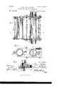
- FIG. 1 is a front elevation illustrating a pair of the present improved receivers arranged at the upper ends of the pneumatic conduits or tubes, with the connections between the same;
- Fig. 2 a longitudinal section of one of the receivers;
- Fig. 3 a longitudinal section at line a; ce, Fig. 2, with parts broken away to show the stop for limiting theslidin g movement of the movable partof the receiver;
- Fig. 4t an enlarged detail section illustrating the packing-ring between the movable and stationary portion of the receiver.
- l and 2 represent,respectively,portions of the up-and-down pneumatic conduits or tubes that extend from point to point or station to station in the building, dre., and through which a forced current of air is maintained by means of a fan-blower or other suitable means, as usual in pneumatic-despatch apparatus.
- the sliding or shifting portion of the receiver consists of the upper and lower counterpart heads 8 and 9, each of which is provided with a pair of hollow ⁇ necks 10 and 11 to receive the sections 12 and 13 of glass tubing, that constitute the receiving-chambers proper of the present receiving apparatus and which are of the same or substantially the same internal diameter as that of main conduits or tubes 1 and 2.
- the movable portion of the receiver When it is desired to transmit a message, the., the movable portion of the receiver will be slid into a position to expose at the sideV of the stationary portion of the receiver the mouth of the clearway-chamber, so that a tubular message-carrier can be introduced into the same, after which the movable receiver portion is slid back so that such chamber will be in line with the main conduit, when the tubular carrier will be carried along with the passing body of air.
- tubular message-carrier at the top of said chamber and provide the lower end of the saine with a 'removable stop 20, usually a removable cross-rod, as shown, so as to support and hold the tubular carrier within said chamber while the same is being moved into line with the main conduit, after which said pin or stop can be removed.
- the receivers when used in series are capable of a very close arrangement with relation to each other, which 'is a matter Yof great importance where a number of different conduits extend to one common receiving or sending station.
- a connection is made between the tops of the receivers by means of the return-bend or gooseneck 21, which is made of an expanded construction, as shown, so as to avoid friction and resistance to the passage of the air in its return from one pneumatic conduit to the other.
- the pneumatic conduits are connected by a bypass of restricted area and consisting of a section ot' tubing 22, secured by suitable couplings 23 to lateral necks 24 of the coupling-heads 25 on the conduits.
- a pneumatic-despatch apparatus comprising in combination, main up-and-down conduits 1 and 2, apair of independent receivers inserted in the conduits near their upper ends, a tubular gooseneck bend 21, connecting ⁇ the upper ends ot' the two receivers together, such bend being of an expanded nature upwardly toward its crown, at which point it has the largest cross-area, and a bypass or cross-tube 23, connecting the two conduits together below the receivers, substantially as set forth.
Description
(No Model.) 2'Sheets-Sheet1, A. 8c J. W. MATHIS. PNEUMATIG DESPATGH APPARATUS.
No. 584,885. Patented June 22,1897.
EEE?
. (No Model.) 2 Sheets-Sheet 2.
A. 8v J. W. MATHIS. PNEUMATIG DESPATGH APPARATUS. No. 584,885.
Patented June 22, 1897.
1 A ilr im Alu Almunia, IIIIHII lll HIlllllllllllllllllllllllllll mum NIIII llNTTnn STATES PATENT a Trice.
AUGUST MATHIS AND JULIEN WV. MATHIS, OF CHICAGQLLNOIS.
PNEUMATICDESPATCI-i APPARATUS.
i SPECFICATION forming part of Letters Patent No. 584,885, dated June 22, 1897'.
Application filed December 26, 1893. Serial No. 494,775. (No model.)
To aZZ whom t may concern:
Be it known that we, AUGUST MATHIS and JULIEN W. MATT-ns, citizens of the United States, and residents of Chicago, in the county of Cook and State of Illinois, have jointly invented certain new and usefullmprovements in Pneumatic-Despatch Apparatus; and we do hereby declare the following to bea full, clear, and exact description of the same, reference being had tothe accompanying drawings, forming a part of this specification.
The present invention relates to that class of apparatus in which messages, dac. inclosed in a tubular carrier are drawn by a blast of air through Va despatch-tube from point to point in a store or building. 1
The object of the present improvement is to provide in connection with the present improved receiver'means for coupling the upper ends of the up-and-down or back-andforth pneumatic conduits or tubes so that the forced current of air passing along the one tube will make a return and back through the other tube or conduit to a fan or other motor by which the forced current of air is maintained within the apparatus, and also in connection with such receiver provide a by-pass for the air at a point below the receiver, so that as the tubular carrier reaches the receiver the air will partly short circuit through such by-pass, and in consequence the speed with which the carrier enters the receiver will be reduced, so as not to ca use a heavy jar or impact against the stop by which the carrier is restrained within such receiver.
We attain the above object by the construction and arrangement of parts illustrated in the accompanying drawings, in which- Figure 1 is a front elevation illustrating a pair of the present improved receivers arranged at the upper ends of the pneumatic conduits or tubes, with the connections between the same; Fig. 2, a longitudinal section of one of the receivers; Fig. 3, a longitudinal section at line a; ce, Fig. 2, with parts broken away to show the stop for limiting theslidin g movement of the movable partof the receiver; Fig. 4t, an enlarged detail section illustrating the packing-ring between the movable and stationary portion of the receiver.
Similar numerals of reference indicate like parts in the several views.
Referring to the drawings, l and 2 represent,respectively,portions of the up-and-down pneumatic conduits or tubes that extend from point to point or station to station in the building, dre., and through which a forced current of air is maintained by means of a fan-blower or other suitable means, as usual in pneumatic-despatch apparatus.
The receivers by which the tubular carriers are received from and delivered to the pneumatic conduits 1 and 2 are inserted in the same at the required points or stations and in the present invention consist each of a pair of counterpart stationaryheads 3 and 4, secured together at the required distances apart by means of the distance-posts 5 and suitable attaching-nuts, as shown, and having tubular necks 6 for the reception of the respective ends of the main pneumatic conduit or tubes, such heads being provided with parallel side flanges '7, that guide the sliding or shifting portion of the receiver in its rectilinear reciprocating movement between said heads. The sliding or shifting portion of the receiver consists of the upper and lower counterpart heads 8 and 9, each of which is provided with a pair of hollow` necks 10 and 11 to receive the sections 12 and 13 of glass tubing, that constitute the receiving-chambers proper of the present receiving apparatus and which are of the same or substantially the same internal diameter as that of main conduits or tubes 1 and 2. The heads 8 and 9 are secured together at the required distance apart by means of the distance-posts 14 and suitable attaching-nuts, as shown, such posts also acting as handles in the manual operation of the same, and the two heads, secured together as above described, constitute the movable portion of the receiver, the movement of which between the guide-flanges 7 of 'the stationary portion of the receiver is limited by the pin or set-screw 15 on the movable member, traveling in the longitudinal recess 16 in the stationary member of the receiver.
` 17 are packing rings surrounding the mouths formed by the hollow necks 6 of the stationary heads 3 and a and let into marginal recesses surrounding the same, and 18 are interposed springs of rubber or like material for forcing said rings outward to a bearing upon the adjacent surfaces of the heads IOO S and 9 of the movable portion of the receiver, the purpose being to form an air-tight joint at such points and prevent leakage of air from the main conduit at such points.
In the present improved construction the receiving-chambers formed by the sections of glass tubing 12 and 13 are in parallel re lation to each other, and it is intended that one or the other will be in line with the main conduit or tube at all times except during the change or shift of one or the other into communication with the main conduit, and one of such chambers will have a clear bore, so as to form a continuation of the main conduit and permit of the free passage of the tubular carriers, while the other will have a stop, usually consisting of a cross-rod 19, arranged at its farther end with relation to the direction in which the iiow of air takes place, so that when such chamber is placed in line with the main conduit the passing tubular carrier will be checked and held within such transparent chamber until by a manual manipulation such chamber is drawn away laterally, so as to permit of the tubular carrier dropping out of the same. In cases where it is not desired to have the inclosing Walls of the aforesaid chambers of a transparent na` ture metal tubes can be substituted for the glass tubes 12 and 13 without departing from the general spirit of our present invention.
When it is desired to transmit a message, the., the movable portion of the receiver will be slid into a position to expose at the sideV of the stationary portion of the receiver the mouth of the clearway-chamber, so that a tubular message-carrier can be introduced into the same, after which the movable receiver portion is slid back so that such chamber will be in line with the main conduit, when the tubular carrier will be carried along with the passing body of air. It is preferable to introduce the tubular message-carrier at the top of said chamber and provide the lower end of the saine with a 'removable stop 20, usually a removable cross-rod, as shown, so as to support and hold the tubular carrier within said chamber while the same is being moved into line with the main conduit, after which said pin or stop can be removed.
By the improved rectilinear construction of the sliding parts, as illustrated in the drawings, the receivers when used in series are capable of a very close arrangement with relation to each other, which 'is a matter Yof great importance where a number of different conduits extend to one common receiving or sending station.
In the construction illustrated in Fig. 1, in which a pair of receivers are shown in place on the upper ends of the up-and-down pneumatic conduits 1 and 2, a connection is made between the tops of the receivers by means of the return-bend or gooseneck 21, which is made of an expanded construction, as shown, so as to avoid friction and resistance to the passage of the air in its return from one pneumatic conduit to the other.
Beneath the receivers the pneumatic conduits are connected bya bypass of restricted area and consisting of a section ot' tubing 22, secured by suitable couplings 23 to lateral necks 24 of the coupling-heads 25 on the conduits. With this construction a by-pass or short circuit of the compressed air is effected after the tubular carrier has passed the same, so that the pressure beneath the same is in a great measure reduced and the tubular conveyer will enter in a very gentle manner into the receiver without undue jar or noise.
Having thus fully described our said invention, whatwe claim as new, and desire to secure by Letters Patent, is
A pneumatic-despatch apparatus comprising in combination, main up-and-down conduits 1 and 2, apair of independent receivers inserted in the conduits near their upper ends, a tubular gooseneck bend 21, connecting` the upper ends ot' the two receivers together, such bend being of an expanded nature upwardly toward its crown, at which point it has the largest cross-area, and a bypass or cross-tube 23, connecting the two conduits together below the receivers, substantially as set forth. Y
In testimony whereof witness our hands this 21st day of December, 1893.
AUGUST MATHIS. y JULIEN IV. MATHIS. In presence ofn ROBERT BURNS, JAMES LAVALLIN.
Publications (1)
| Publication Number | Publication Date |
|---|---|
| US584885A true US584885A (en) | 1897-06-22 |
Family
ID=2653555
Family Applications (1)
| Application Number | Title | Priority Date | Filing Date |
|---|---|---|---|
| US584885D Expired - Lifetime US584885A (en) | Pneumatic-despatch apparatus |
Country Status (1)
| Country | Link |
|---|---|
| US (1) | US584885A (en) |
Cited By (1)
| Publication number | Priority date | Publication date | Assignee | Title |
|---|---|---|---|---|
| US3063080A (en) * | 1961-01-11 | 1962-11-13 | Panhandle Eastern Pipe Line Co | Combination gate valve and ball launcher and catcher for use in pressure flow lines |
-
0
- US US584885D patent/US584885A/en not_active Expired - Lifetime
Cited By (1)
| Publication number | Priority date | Publication date | Assignee | Title |
|---|---|---|---|---|
| US3063080A (en) * | 1961-01-11 | 1962-11-13 | Panhandle Eastern Pipe Line Co | Combination gate valve and ball launcher and catcher for use in pressure flow lines |
Similar Documents
| Publication | Publication Date | Title |
|---|---|---|
| US584885A (en) | Pneumatic-despatch apparatus | |
| US455021A (en) | Equipment of railway-trains | |
| US420209A (en) | Pipe-coupling for railway-cars | |
| US623416A (en) | John alexander mccrory | |
| US872174A (en) | Automatic train-pipe coupling. | |
| US1530651A (en) | Inflation-tube coupling | |
| US918230A (en) | Automatic pipe-coupling head. | |
| US743935A (en) | Line-pipe coupling. | |
| US296547A (en) | Elegtbigal cootectoe if pipe couplings foe aie beakes | |
| US128760A (en) | Improvement in flexible pipe-joints | |
| US701833A (en) | Train-pipe coupling. | |
| US329326A (en) | Hose-coupling | |
| US407839A (en) | Peter g | |
| US961638A (en) | Steam and air pipe coupling for cars. | |
| US812532A (en) | Automatic air-pipe coupling. | |
| JPH0355376B2 (en) | ||
| US1297808A (en) | Car-coupling. | |
| US461532A (en) | Automatic pipe-coupling | |
| USRE11673E (en) | Fourth to john r | |
| US959777A (en) | Smoke-conveying attachment for railway-trains. | |
| US558825A (en) | Pneumatic-despatch apparatus | |
| US693125A (en) | Train-pipe coupling. | |
| US771002A (en) | Automatic train-pipe coupling. | |
| US654690A (en) | Pneumatic-despatch tube. | |
| US620564A (en) | Combined air-operated car-coupling and train-pipe-coupling |