US583039A - Electric-signal distributer - Google Patents
Electric-signal distributer Download PDFInfo
- Publication number
- US583039A US583039A US583039DA US583039A US 583039 A US583039 A US 583039A US 583039D A US583039D A US 583039DA US 583039 A US583039 A US 583039A
- Authority
- US
- United States
- Prior art keywords
- contact
- plate
- series
- plates
- magnet
- Prior art date
- Legal status (The legal status is an assumption and is not a legal conclusion. Google has not performed a legal analysis and makes no representation as to the accuracy of the status listed.)
- Expired - Lifetime
Links
- 230000000875 corresponding effect Effects 0.000 description 33
- 230000000994 depressogenic effect Effects 0.000 description 12
- 239000011810 insulating material Substances 0.000 description 10
- 230000000694 effects Effects 0.000 description 7
- 238000000034 method Methods 0.000 description 7
- 239000004020 conductor Substances 0.000 description 6
- 230000006978 adaptation Effects 0.000 description 2
- 238000010586 diagram Methods 0.000 description 2
- 230000010355 oscillation Effects 0.000 description 2
- 230000000284 resting effect Effects 0.000 description 2
- 102000004726 Connectin Human genes 0.000 description 1
- 108010002947 Connectin Proteins 0.000 description 1
- 238000010276 construction Methods 0.000 description 1
- 230000003111 delayed effect Effects 0.000 description 1
- 230000000881 depressing effect Effects 0.000 description 1
- 230000001747 exhibiting effect Effects 0.000 description 1
- 239000000463 material Substances 0.000 description 1
- QEVHRUUCFGRFIF-MDEJGZGSSA-N reserpine Chemical compound O([C@H]1[C@@H]([C@H]([C@H]2C[C@@H]3C4=C(C5=CC=C(OC)C=C5N4)CCN3C[C@H]2C1)C(=O)OC)OC)C(=O)C1=CC(OC)=C(OC)C(OC)=C1 QEVHRUUCFGRFIF-MDEJGZGSSA-N 0.000 description 1
- 230000000630 rising effect Effects 0.000 description 1
- 239000004576 sand Substances 0.000 description 1
Images


Classifications
-
- H—ELECTRICITY
- H01—ELECTRIC ELEMENTS
- H01H—ELECTRIC SWITCHES; RELAYS; SELECTORS; EMERGENCY PROTECTIVE DEVICES
- H01H67/00—Electrically-operated selector switches
- H01H67/22—Switches without multi-position wipers
- H01H67/26—Co-ordinate-type selector switches not having relays at cross-points but involving mechanical movement, e.g. cross-bar switch, code-bar switch
Definitions
- GMKM mum hkwamuwm 0M- m: uoRRvs PETERS Co, woYc-Llmo, wxsnmcmx, u. c.
- W ⁇ mmewzs m norms PETERS cu. PHDYOMTHQ. WILSNINGTON. a. c.
- the objects of this invention are twofold: first, to actuate, by meansof a series of electrical impulses conveyed by a single conducting-wire, a signal or other device at any one of several points or stations connected by such conducting-Wire and provided with actuating devices without producing a complete operation of any other actuating device in the series than the one designated, and, second, to produce, by means of a series of electrical impulses sent over a single wire connecting several points or stations, any one of a series of distinct results, such as actuating signals or printing letters or characters simultaneously at one or more of the connected stations,
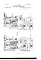
- Figure 1 is a partial plan view of the portion of the mechanism used interchangeably in sending or receiving, together with the switches used in converting this section of the device from transmitting to receiving purposes.
- Figs. 2 and 3 are respectively a side and a rear elevation of the same portion of the mechanism on the cross-sections X X and y y of Fig. 1.
- FIG. 4 shows an enlarged view of the pairs of contact-plates shown in position in Fig. (i. Fig. 8 shows in the lower portion of the sheet a diagrammatical view of the electrical-contact parts of the portion of the device shown in Fig. 1 with their connections and in the upper portion of the sheet a plan view of the exclusively-receiving section of the device, intended to accomplish the latter of the two general results mentioned at the beginning of this specification, the figure as a whole exhibiting the manner in which the efiect of a series of electrical impulses may be directed to a specified one of a series of signals or other devices actuated by a respective electromagnet.
- Fig. 4 shows an enlarged view of the pairs of contact-plates shown in position in Fig.
- Fig. 8 shows in the lower portion of the sheet a diagrammatical view of the electrical-contact parts of the portion of the device shown in Fig. 1 with their connections and in the upper portion of the sheet a plan view of the exclusively-receiving section of the device,
- FIG. 5 shows in elevation a sectional view of Fig. 8 011 the cross-line z 2.
- Fig. 9 repeats the diagram of Fig. 8 for the purpose of showing the manner in which the effect of a series of electrical impulses is directed to the first of the two general results intended by the deviceviz., that of actuating a designated one of a series of signals or other actuating devices, each located at a separate point or station on a line.
- FIG. 10 shows in a general and more or less diagrammatical way the relation of the mechanism at a sending-station to that at a receiving-station and is designed chiefly to show the changes in adjustment in the interchangeable mechanism, according to its use for sending or receiving purposes.
- the device consists of a series of oscillating arms A A pivoted by a central shaft A and extending horizontally in direction approximately at right angles to each other.
- Each of the arms A bears an armature A which may be actuated by an electromagnet A, the retracting-spring A acting in opposition to the influence of said electromagnet A.
- the number of the electromagnets A in the series varies with the number of signals or devices to be operated, six being, perhaps, the more usual number.
- each arm A To the free end of each arm A is pivoted a bar F, which is adapted to be actuated in a longitudinal direction by the oscillations of said arm A.
- Two blocks F F of insulating material and having deep longitudinal grooves or slots on their lower sides, are mounted one on either side of each bar F upon metallic supportingbraces D D and adapted to glide easily thereon. These blocks are provided with shoulders or projections which are engaged by an adjustable head F attached to the bar F and are thereby drawn forward when the corresponding magnet A is energized.
- contact-brush e is carried forward to a second contact-plate c, adjacent to contact-plate e.
- each arm A of the se ries On the free end of each arm A of the se ries is loosely mounted a block G, of insulating material, carrying a contact-spring which rests normally against plate 6 attached to the next succeeding block F of the series and just below the insulating projection e of said block F, beingprovisionally engaged thereby.
- the position of block G is adjusted by m cans of a nut G on the end of arm A
- it may, by reason of its engagement with the projection c on block F, be carried forward on arm A when block F is actuated byits corresponding magnet A. In that case it is restored to its normal position simultaneously with block F by means of a spring ll", attached to said block F.
- each arm A constitutes a contact-point a, which lies between two contact-plates a a attached to an oscillating block B, of insulating material, pivoted at B to the base A or to a standard erected thereon.
- Frictional springs a a" rest against and make contact with plates a and a respectively.
- Point a is held normally, by force of retracting-sprin g A, against plate a which in turn rests against an adjusting contactscrew 13, inserted in and making electrical contact with the next succeeding brace D of the series.
- Plate a is adjusted by means of a screw a and should be so placed that the distance normally separating it from the point a will be considerably less than that traversed by said point a when it is actuated by magnet A or the retractin g-sprin g A.
- a contact-sprin g K which rests normally against a contact-plate K also attached to standard K.
- a block K is attached to arm -F and adapted, when the latter is actuated, to strike spring K and drive it from its contact with plate K Idesire to be understood as not limiting myself to the minutiae of these details in every particular.
- wires t which in certain cases may be joined electrically at the transmitting-keyboard by the pressure of a keylcver L, bringingaconducting-plate L into contact with a pair of con d ucti n g-bars L 1), to which said wires i 1 are attached, as will be hereinafter more fully described in connection with the transmitting-keyboard.
- the arm 25 of switch V in the path of the local current generated by battery P, Figs. 9 and 10 is thrown to plate i and the current proceeds, by wire t, switch-arm t contact-plate 6 wire t to the contact-points of relay R.
- Said relay R is actuated by the main current and serves to produce in the 10- cal current the same order of impulses as that occurring in the main current.
- the local current passes from the armature-lever of relay R by wires 25 and 25 to the arm of switch V which in receiving is thrown to plate 15 so as to pass the current directly via wire to the first supporting-brace D of the series before described.
- switches V and V are closed, as shown in Fig. 10.
- the current then passes through brace D contact-brush e, plate e wire 15 switch V and wire i to electromagnet A and thence by wires t 25 to battery P again.
- This serves to energize magnet A, and thus to actuate arm A and bar F and all connected parts.
- Blocks F F will be drawn forward by head F and the contact-brush e will be drawn forward to rest on plate 6
- magnet A will remain energized until a break occurs in the main current, and consequently a break in the local current, which will cause a release of magnet Arms A A will then begin to return to normal position under the influence of retracting-spring A Point at will immediately be brought into contact with plate a and the path of the current will be carried from contact-point a via plate a spring of, wire switch V (closed,) wire the second supporting-brace D of the series, the contactbrush 6 of the second block F of the series, and thence to the second magnet A in the 'manner described in the case of the first magnet A of the series.
- the second magnet A will be energized and not the first, causing a movement of the corresponding arms A A and blocks F F.
- block F of the second magnet A in the series will be drawn forward before spring G of the first magnet A reaches its normal position in contact with plate 6 of said second block F and spring G will fall on plate 6 of said second block F; but if the break in the current be protracted the spring G will reach plate 6 before the latter is actuated and will remain in contact therewith, being carried forward by means of its engagement with projection e on the second block F, as before described.
- Magnot A will be energized and will draw arm A and bar F forward, as before, until the contact-brush 6 passes the plate 6 and until block K strikes spring K and drives it from contact with plate K thus breaking the current energizing magnet A.
- contact point a will immediately be thrown against plate a and out of contact with plate a thus entirely excluding the current from the former magnet A.
- the transmitting-keyboard consists of a series of levers L, of insulating material, mounted pivotally upon a shaft which is supported by standards L attached to any suitable base L
- Levers L are held normally upward by means of a series of springs L and are each provided with a press-button L hearing some designated letter or character.
- the upward motion of each of the levers L is limited by a cross-bar L, mounted above their free ends.
- levers L Running transversely beneath the forward portions of levers L are a series of bars L L, of conducting material, arranged in pairs and mounted on vertical rods L rising from the base L of the keyboard. These bars are held normally upward by spiral springs surrounding rods L, and their upward movement is limited by nuts screwed to the tops of rods L. The number of pairs of bars in the series should equal the number of pairs of magnets A used.
- a series of small conducting-plates L are attached to the lower margins of the key-levers L in such a position that when any key-lever is depressed each plate L will strike the upper margins of a pair of bars L L and will join them electrically.
- each pair of bars L L in the series are joined, respectively, by a conducting-wire 25 to the contactpoints of one of the switches before described.
- Two levers M' one on either side of the keyboard, are' pivoted to a transverse rod M, mounted on supports M and are held normally upward by a spring M beneath.
- a contact-plate ll attached to one of the levers M is held normally against a contact-pin M depending from any suitable support, by the tension of said spring M
- a cross-bar M of conducting material, attached to the ends of levers h extends beneath the levers L in such a position that the depression of any lever L will strike it and carry it downward till it strikes a contact-pin M mounted on an arm attached to standard M 3y this arrangement the depression of any key-lever L will break the contact between plate l ⁇ l"' and contact-pin l ⁇ ' 6 and will cause a contact of cross-bar M with contact-pin M which latter are join ed, respectively, by conductingwires i t to the contact-plates 15 25 of switch V and thus by this contact a provisional path will be formed for the local current around said switch V as before described.
- Figs. 6 and 7. Another method of imparting long and short breaks to the main current is shown in Figs. 6 and 7.
- a bent lever L is placed beneath the forward ends of the key-levers L and pivoted to standards L L".
- a bar L which is drawn by a retracting-sprin g L ,causin g an upward tendency of the bar L toward the key-levers L.
- a contact-lever L which is fulcrumed to a standard L Lever L bears a contact-brush L ,which is adapted to sweep over a segment L of conducting material when lever L is actuated. This will evidently occur by the depression of any key-lever L in the series.
- segment L From the inner margin of segment L are cut sections of uniform width and at uniform IIO intervals, corresponding in number to the pairs of conducting-bars L L.
- the gaps or slots thus made in segment L are partially filled by contact-plates L, the remaining unfilled portion of each gap being chiefly on one side of these plates.
- Each of the plates L is electrically connected by wires t with one of the conductingbars L while each of the bars L is similarly connected with the segment L from which the plates L are normallyinsulated.
- a movable segment L of conducting material is pivoted also at L", bearing two shoulders L L against which the end of lever L is adapted to strike when actuated as described.
- Segment L is held normally by lever L against a contact-plate L is in contact with plate L and brush L is in contact with segment L, the main line will be continuous through segment L plate L segment L brush L and lever L. It will also be continuous when brush L is in contact with a plate L provided the conducting-bar L to which that plate is joined, is electrically connected with its corresponding bar L by means of one of the plates L as before described. In this latter case there would be but a slight break in the main current as the brush L passed over the narrow space between the plate L and segment L while in cases where the plate L is not in electrical connection with segment L by means of such plate L joining the corresponding conducting-bars L L the current will be broken while the brush L is passing over the entire gap in segment L containing the plate L designated.
- lever L will be actuated, carrying brush L over segment L and each of the small contact-plates L with the result of producing a short break in the current when a plate L is crossed having electrical connection with segment L and a longer break when a plate L is crossed having no such connection, these variations depending on the presence or absence of the plates L on the key-lever depressed the same as in the process first described.
- lever L will strike shoulder L of the segment L driving the seg ment from. its contact with plate L thus causing an interruption of the main current while lever L is being restored to its normal position by action of spring L.
- the portion of the mechanism required ex clusively at the receiving-station includes a second local battery P, the contact-springs G and contact-plates 6 2 before described, the signals or other devices to be operated,
- the first of the series of sliding blocks I is provided with a contact-brush 1) similar to the brushes 6, attached to block F before described.
- This brush rests normally on a contact-plate b and is adapted to be carried with the movement of block F to a second contact-plate 12
- a contact-brush e resting normally on a false plate and adapted to be carried by the movement of block F to contact with a conducting-plate 6 remaining in contact therewith only while the corresponding magnet A" is energized and the head F is actuated.
- One of the first plates 6 e of the series is connected by wire 1 or 6", respectively, to the second spring G, one of the second plates 6 e is similarly connected with the third spring G, and so on, the last plate 6 or 6 being connected with brush a of block F If the current be not interrupted between plate b and brush 6 it will, when the latter is in contact with plate 6 proceed thence by wire t to the actuating-magnet of signal T, which it will energize, passing through wire 25 to plate d and thence by brush d wire 25 magnet E, and wire 25 to battery P again, energizing magnet E, which will restore brush (Z block F, and brush 1) to their normal positions.
- the mechanism for actuating any one of a series of signals or other devices simultaneouslyat one or more receiving-stations which is the second of the described objects of this invention, consists of a series of electrom agnets N", Figs. Sand 5, which, by means of connectin g-bars N impart a slight rotary motion to horizontal shaft N, suitably mounted on standards inserted in the base beneath.
- each shaft N is rigidly attached one or more drivers N, of insulating material, which engage a series of movable contact-plates N by means of slots on the lower margins of the latter.
- drivers N of insulating material
- the plates N are carried forward and backward by the oscillations of shafts N.
- One end of each sliding plate N in the series rests continually on an initial contact-plate N, while the other end rests on a terminal plate N and is carried to a second terminal plate N when actuated by the corresponding driver N.
- each con tact-plate c of the series before described is connected by wire t" with the next succeeding contact-spring G while each of the corresponding plates 6 is connected, respectively, with the initial contact-plates N by wires t
- the current when a spring G falls upon a plate 0 the current is carried directly to the next spring G but when a spring G falls on a plate 6 the current will be carried to the corresponding initial plate N, and thence by sliding plate N" to the firstterminal plate N, from which it will proceed by wire 1', magnet N wires i I to battery P
- This will energize magnet N and cause it to actuate driver N and carry sliding plate N forward to the second terminal plate N, by which means the current will be interrupted through magnet N and carried by wires and Z to the next contact-spring G".
- a second series of sliding plates N similar to plates N and similarly actuated are arranged in the following orderviz., one sliding plate for the first shaft N in the series, two for the second, four for the third, and so on, each shaft N having double the number of plates of the preceding one.
- Each of these sliding plates N" rests upon an initial contact-plate N and is adapted to be carried forward to rest upon the initial contact-plate N of a sliding plate N" corresponding to the next shaft N of the series.
- Each terminal plate is electrically joined to an initial plate N of the nextadvanced set of such plates, to which no sliding plate )1 is carried from the previous set. All the sliding plates of any set are actuated simultaneously when the shaft N corresponding thereto is oscillated. It will readily be discovered that for any position of the sliding platesh there is one path from the first initial plate N to the last set of plates N and only one, and for every variation made in the arrangement of those plates by the operations of one or more of the shafts N a different path is opened, the number of the final emerging paths indicated by the wires i being equal to that power of two denoted by the number of shafts H in the series.
- an electromagnet N designed to actuate a signal or any special device.
- lVhen brush 6 is carried into contact with plate a the current proceeds by wire 15 to the first initial plate N thence by one of the paths described through plates N N N to one of the final plates N and from that by the corresponding wire 23 and magnet N to wire whence it reaches battery P in the manner already described in connection with the actuating of single signals.
- This energizes the magnet N in the particular path opened and causes it to actuate mechanism for printing a character or producing a signal or other special effect, as desired.
- the corresponding magnet N will be energized at each receiving-station on the line and the corresponding effect produced at each of such stations simultaneously.
- Shafts N are restored to normal position by means of a bar N which is actuated longitudinally in connection with the mechanism operated by the magnetsN in a manner not here shown.
- a series of bent levers actuated by electromagnets and retracting-springs and with sliding bars of insulating material actuated in connection with and during the advance movement only of said levers
- a series of contact-plates connected to adjustable pivoted blocks and adapted to divert the electric current which energizes said electromagnets
- an insulating contact device attached rigidly to each of said levers and adapted to move between and make contact with two insulated contactplates, said contact device being separated from said contact-plates by a distance less than that covered by said contact device in returning to its normal position under the influence of its corresponding contractings'pring, one of said contact-plates having provisional electric connection with the magnet actuating the lever corresponding thereto, and the other contact-plate similarly connected to the next advanced magnet of the series and adapted to rest in its normal position against a contact-stop, said stop having a constant electrical connection with said advanced magnet, whereby an electric current reaching said contact device during the advance movement thereof may be carried to said
- a series of levers actuating magnets and retractingsprings, sliding bars of insulating material actuated in connection therewith, an insulated contact device attached rigidly to each of said levers, and contact-plates each attached to an oscillatingblock and adapted to make contact with a corresponding contact device when the latter begins its retrograde movement
- a keyboard consisting of a series of insulated key-levers held normally upward by springs, said levers having insulated contact-plates so placed that when any key-lever is depressed, each of said key-lever contactplates electrically joins the two members of a series of pairs of spring-supported contactplates, one of the members of each pair of said spring-supported contact-plates having electrical connection respectively with one of the said contact-plates attached to an oscillating block, and the other member of each pair of said spring-supported contact-plates having electrical connection with the act-nating-magnet next in series above the one by which said attached contact-plate is actuated, whereby any desired combination of
- a segmental contact-plate connected with said main line on one side of a switch, and having radiating slots partially filled with insulated contactplates, a lever bearing a commutator c011- nected on the opposite side of said switch with the main line, and adapted to move over said segmental contact-plate and said radiating slots and insulated contact-plates, a series of spring-supported key-levers having insulated contact-plates adapted when the key-lever is depressed to electrically join the two members of a series of pairs of spring-supported contact-plates, one member of each of such pairs of contact-plates being electrically connected with said segmental contact-plate, and the other member being connected respectively with one of said contact-plates in the slots of said segment, a rod beneath the ends of said key-levers and connected to said commutator-lever, whereby when any of said key-levers are depressed said commutator-lever will be carried across said slots and the contact-plates therein, and the contact
Landscapes
- Breakers (AREA)
Description
(No Model.) 6 Sheets-Sheet 1.
RH. PISK. ELECTRIC SIGNAL DISTBIBUTER.
No. 583,039. Patented May 25,1897.
THE mums PETERS cu. wummuma, wASH|NGTON,-D. c.
(No Model.) 6 Sheets-Sheet 2. P. H. FISK. ELECTRIC SIGNAL DISTRIBUTER.
Patented May 25,1897
i I, I
GMMW sw m. YN 5 THE ncmms wzrzas co, PHDTO-LITHQ. WASHINDYON. n. c.
(No Model) 6 Sheets-Sheet 3.
,P. H. PISK. ELECTRIC SIGNAL DISTRIBUTER.
No. 583,039. Patented May'25, 1897.
Rik
GMKM mum hkwamuwm 0M- m: uoRRvs PETERS Co, woYc-Llmo, wxsnmcmx, u. c.
6 Sheets-Sheet 4;
(No Model.)
v v P. H. FISK. ELECTRIC SIGNAL DISTRIBUTER.
' Patented May 25, 1897.
a 2, e OMKMAMMm Bx WMWW m.
ant-22f n: nouns PETERS co PHOTO-LITHD. \VASHWGYON. :1v :2.
6 Sheets Sheet 5.
(No Model.)
'P. H. FISK.
ELECTRIC SIGNAL DISTRIBUTER.
Patented May'25. 1897.
W \mmewzs m: norms PETERS cu. PHDYOMTHQ. WILSNINGTON. a. c.
(No ModeLY 6 SheetsSheet s.
P. HQPISK.
v ELECTRIC SIGNAL DISTRIBUTER. No. 583,039. Patented May 25,1897.
IIIIIIIIII I I N R m Wwfiassas. 3) H Ol x i mum 0W.
THE NORRIS PETERS co. morauwo \VASNINGTONY n. c.
UNITED STATES PATENT OFFICE.
PLINY ll. FISK, OF NORTH BRANCH, MINNESOTA.
ELECTRIC-SIGNAL DISTR IBUTER.
SPECIFICATION forming part of Letters Patent No. 583,039, dated May 25, 1897.
' Application filed October 28, 1895. Serial No. 567,124. (No model.)
To CI/ZZ ZUYQ/OTI b it may concern.-
Be it known that I, PLINY H? FISK, a citizen of the United States,residin g at North Branch in the county of Chisago'and State of Minnesot-a, have made certain new and useful Improvements in Electric-Signal Distributers, of which the following is a specification.
The objects of this invention are twofold: first, to actuate, by meansof a series of electrical impulses conveyed by a single conducting-wire, a signal or other device at any one of several points or stations connected by such conducting-Wire and provided with actuating devices without producing a complete operation of any other actuating device in the series than the one designated, and, second, to produce, by means of a series of electrical impulses sent over a single wire connecting several points or stations, any one of a series of distinct results, such as actuating signals or printing letters or characters simultaneously at one or more of the connected stations,
the operator or sender of the impulses being at another of the said connected stations. 111 the accomplishment of these objects a portion of the mechanism used in transmitting the electrical impulses is converted into a receiving mechanism by the mere reversing of a number of switches. Other sections of the device are used exclusively for transmitting the impulses, and still others are used only in referring the effect of the impulses at the receiving-station to the particular signal or other device to be actuated.
In the accompanying drawings are shown the details of my invention, and in the following specification is described the operations of the several parts and afterward the operation of the mechanism as a whole in producing either of the two general results first mentioned.
In the accompanying drawings, Figure 1 is a partial plan view of the portion of the mechanism used interchangeably in sending or receiving, together with the switches used in converting this section of the device from transmitting to receiving purposes. Figs. 2 and 3 are respectively a side and a rear elevation of the same portion of the mechanism on the cross-sections X X and y y of Fig. 1.
and other parts of the exclusively-transmitting portion of the device. Fig. 4 shows an enlarged view of the pairs of contact-plates shown in position in Fig. (i. Fig. 8 shows in the lower portion of the sheet a diagrammatical view of the electrical-contact parts of the portion of the device shown in Fig. 1 with their connections and in the upper portion of the sheet a plan view of the exclusively-receiving section of the device, intended to accomplish the latter of the two general results mentioned at the beginning of this specification, the figure as a whole exhibiting the manner in which the efiect of a series of electrical impulses may be directed to a specified one of a series of signals or other devices actuated by a respective electromagnet. Fig. 5 shows in elevation a sectional view of Fig. 8 011 the cross-line z 2. Fig. 9 repeats the diagram of Fig. 8 for the purpose of showing the manner in which the effect of a series of electrical impulses is directed to the first of the two general results intended by the deviceviz., that of actuating a designated one of a series of signals or other actuating devices, each located at a separate point or station on a line. It also shows in diagram the operation of the portion of the device used interchangeably in sending and receiving the direction of the local current from battery P, by which this portion of the mechanism is actuated, and of the local current from battery P, by which, in the case of receiving, the effect of the transmitted impulses is carried to the final actuating mechanism, and the relays and switches by means of which the main current is brought into relation with the former of these currents. Fig. 10 shows in a general and more or less diagrammatical way the relation of the mechanism at a sending-station to that at a receiving-station and is designed chiefly to show the changes in adjustment in the interchangeable mechanism, according to its use for sending or receiving purposes.
In detail the device consists of a series of oscillating arms A A pivoted by a central shaft A and extending horizontally in direction approximately at right angles to each other. Each of the arms A bears an armature A which may be actuated by an electromagnet A, the retracting-spring A acting in opposition to the influence of said electromagnet A. The number of the electromagnets A in the series varies with the number of signals or devices to be operated, six being, perhaps, the more usual number.
To the free end of each arm A is pivoted a bar F, which is adapted to be actuated in a longitudinal direction by the oscillations of said arm A.
Two blocks F F, of insulating material and having deep longitudinal grooves or slots on their lower sides, are mounted one on either side of each bar F upon metallic supportingbraces D D and adapted to glide easily thereon. These blocks are provided with shoulders or projections which are engaged by an adjustable head F attached to the bar F and are thereby drawn forward when the corresponding magnet A is energized. They are restored to normal position by means of a series of levers II, which are pivoted to standards 11*", one end being adjustably attached to the next lower bar F of the series and the other end provided with a head ll, adapted to engage blocks F F and drive them backward to normal position when the preceding bar F is actuated by its corresponding magnet A The first pair of blocks F F are restored to normal position by special electromagnets E E acting upon two armatures (7 (1 connected by yokes d d" and pins (1 (1 to blocks F F. Each block I of the series is provided with a contact-brush a having constant electrical contact in any suitable manner with its corresponding supporting-brace D and extending downward to contact with a plate attached to base A beneath. When block F is carried forward by head F contact-brush e is carried forward to a second contact-plate c, adjacent to contact-plate e. To the outward lateral surface of each block F, except the first in the series, are attached two contact-plates c c", separated by a pointed project-ion c of the body of the insulating-block F, to which they are attaehed.
On the free end of each arm A of the se ries is loosely mounted a block G, of insulating material, carrying a contact-spring which rests normally against plate 6 attached to the next succeeding block F of the series and just below the insulating projection e of said block F, beingprovisionally engaged thereby. The position of block G is adjusted by m cans of a nut G on the end of arm A In certain cases, as hereinafter described, it may, by reason of its engagement with the projection c on block F, be carried forward on arm A when block F is actuated byits corresponding magnet A. In that case it is restored to its normal position simultaneously with block F by means of a spring ll", attached to said block F. The free end of each arm A constitutes a contact-point a, which lies between two contact-plates a a attached to an oscillating block B, of insulating material, pivoted at B to the base A or to a standard erected thereon. Frictional springs a a" rest against and make contact with plates a and a respectively. Point a is held normally, by force of retracting-sprin g A, against plate a which in turn rests against an adjusting contactscrew 13, inserted in and making electrical contact with the next succeeding brace D of the series. Plate a is adjusted by means of a screw a and should be so placed that the distance normally separating it from the point a will be considerably less than that traversed by said point a when it is actuated by magnet A or the retractin g-sprin g A.
To a standard K, made of insulating material, is attached a contact-sprin g K which rests normally against a contact-plate K also attached to standard K. A block K is attached to arm -F and adapted, when the latter is actuated, to strike spring K and drive it from its contact with plate K Idesire to be understood as not limiting myself to the minutiae of these details in every particular. For instance, if it be found more convenient in construction to combine blocks F F in one, or to place the contact-plates e c on the upper surface of block F and attach the contact-brushes c" to the brace D allowing themto bear on block F instead of on base A, as shown, or to pivot block 3 to the standard at A instead of at the remote point shown, or to make use of any of the manifestly-numerous possible vibrations from the method shown of producing the same identical results in a slightly more convenient way, I claim protection in adopting them.
The following electrical connections will be here noticed for the purpose of describing the switches employed in this part of the device: First, a line, eonsistingof wires Wand connecting each plate (J with its corresponding magnet A through contact-plate K and contact-spring K, or through switch V" when it is closed, as for purposes hereinafter described. Second, a line by wire 1' connecting plate a with arm A said arm A being of conducting material throughout. Third, a line by wire 2 connecting spring a with plate Fourth, a line by wires i con n ecting spring a with the next succeedingbrace D of the series. In this line is placed a switch which when open breaks the line. Fifth, a provisional path around said switch is afforded by wires t, which in certain cases may be joined electrically at the transmitting-keyboard by the pressure of a keylcver L, bringingaconducting-plate L into contact with a pair of con d ucti n g-bars L 1), to which said wires i 1 are attached, as will be hereinafter more fully described in connection with the transmitting-keyboard.
Before proceeding to describe further details it is desirable to show the method of using,both in sending and receiving electrical impulses, the mechanism thus far described, and it will be found that these operations will be most readily understood by considering first those that occur iureceiving impulses.
In the case of receiving a series of electrical impulses the arm 25 of switch V in the path of the local current generated by battery P, Figs. 9 and 10, is thrown to plate i and the current proceeds, by wire t, switch-arm t contact-plate 6 wire t to the contact-points of relay R. Said relay R is actuated by the main current and serves to produce in the 10- cal current the same order of impulses as that occurring in the main current. The local current passes from the armature-lever of relay R by wires 25 and 25 to the arm of switch V which in receiving is thrown to plate 15 so as to pass the current directly via wire to the first supporting-brace D of the series before described.
In receiving impulses switches V and V are closed, as shown in Fig. 10. The current then passes through brace D contact-brush e, plate e wire 15 switch V and wire i to electromagnet A and thence by wires t 25 to battery P again. This serves to energize magnet A, and thus to actuate arm A and bar F and all connected parts. Blocks F F will be drawn forward by head F and the contact-brush e will be drawn forward to rest on plate 6 This throws the electrical current forward through wire i to arm A thence by contact-point a, which by the movement of arm A will be now in contact with plate a through spring a and wire to plate 6 and from thence by wires 75 switch V wire i magnet A wires 25 and 29 to battery P, as at first. Thus magnet A will remain energized until a break occurs in the main current, and consequently a break in the local current, which will cause a release of magnet Arms A A will then begin to return to normal position under the influence of retracting-spring A Point at will immediately be brought into contact with plate a and the path of the current will be carried from contact-point a via plate a spring of, wire switch V (closed,) wire the second supporting-brace D of the series, the contactbrush 6 of the second block F of the series, and thence to the second magnet A in the 'manner described in the case of the first magnet A of the series. Thus when the current is again renewed the second magnet A will be energized and not the first, causing a movement of the corresponding arms A A and blocks F F. If this renewal of the current be instantaneous, block F of the second magnet A in the series will be drawn forward before spring G of the first magnet A reaches its normal position in contact with plate 6 of said second block F and spring G will fall on plate 6 of said second block F; but if the break in the current be protracted the spring G will reach plate 6 before the latter is actuated and will remain in contact therewith, being carried forward by means of its engagement with projection e on the second block F, as before described. The same order of movements will be repeated until each of the magnets A in the series has been energized, and as a result each spring G of the series will rest finally in contact with either plate 6 or e of the next succeeding block F, according as the intervals between the energizing of the two successive magnets A involving those parts have been short or long. From the final plate C of the series the current from battery P is carried by wire t plate d, brush 0Z wire t to magnet E, and from thence it proceeds by wire Z to battery P again. This energizes magnet E and causes a restoration of the first block F to its normal position, the current through said magnet E being finally broken by the withdrawing of brush d from plate 2 in connection with the movement of yoke d as before described.
The final effects produced at the receivingstation by the various combinations of the springs G with the plates 6 and a will be explained hereinafter. The use of this portion of the mechanism in sending impulses is as follows: First, the arm of switch V is thrown to plate so as to cause the main current to pass through the contact-points of relay R The arm of switch V is thrown to plate 27, so as to carry the local current from battery P through relay-magnet R and exclude it from the contact-points of relay B. This, in effect, reverses the relation of the local current to the main current from that which they hold in receiving and causes the makes and breaks in the former to be transmitted to the latter. Furthermore, the arm of switch V, Fig. 9, is thrown to plate by which the local current is made to pass through a contact-bar M and a contactplate M", which are joined when a transmitting-lever, as L, is depressed, as will be hereinafter more fully described. The local current from battery P now flows through wire t, arm t plate 15 relay-magnet R wire 25, arm of switch V contact-plates 75 wire t contact-bar M contact-plate M wire t, plate 75, wire to supporting-brace D and thence to contact-plate a as before described. All the switches of the series V and V are open in transmitting. The current will proceed from plate 6 through wire 75, plate K spring K wire i to magnet A, and thence by wires 15 and i to battery P in themanner described in the process for receiving. Magnot A will be energized and will draw arm A and bar F forward, as before, until the contact-brush 6 passes the plate 6 and until block K strikes spring K and drives it from contact with plate K thus breaking the current energizing magnet A. By the recoil of arms A and A before described, contact point a will immediately be thrown against plate a and out of contact with plate a thus entirely excluding the current from the former magnet A. Arm A will continue its return movement after point a has reached plate a the latter being pushed onward by said point a until said plate strikes the end of the contact stop-pin B which will arrest the further progress of arm A The provisional path from plate a via plate a", wire i bars L L, wires 6 and i, will admit the current to the second conducting-brace D of the series the instant point a strikes plate a in all cases where said provisional path is closed by means of the presence of a conducting-plate L on the transmitting-lever L depressed, having contact with the respective pair of conducting-bars L L, as before mentioned; but in the cases where such conducting-plate L is lacking to join a pair of said conducting-bars L L electrically when the corresponding transmitting-lever is depressed the current cannot reach the next brace D until arm A has completed its return movement and plate a is brought in contact with the stop-screw B which has contact with said brace D From the second supporting-brace D the current will reach the originating-battery through the second magnet A in the manner described in connection with the process of receiving impulses, and the break in the local current will end.
In the first of the above cases there willbe avery slight break in the local current merely while point a is passing from plate a to a while in the latter cases there will be a relativelylong one. These impulses and breaks will be imparted to the main line by means of the relay R and will tend to actuate all instruments on the line that are arranged in the manner described for receiving impulses. The arrangement of the various switches and other parts involved in the interchangeable use of this portion of the device is shown diagramatically in Fig. 10, where the adaptation of an instrument for use in transmitting impulses is shown at the left of the figure and the adaptation of another instrument for use in receiving impulses at a different station is shown at the right.
The transmitting-keyboard consists of a series of levers L, of insulating material, mounted pivotally upon a shaft which is supported by standards L attached to any suitable base L Levers L are held normally upward by means of a series of springs L and are each provided with a press-button L hearing some designated letter or character. The upward motion of each of the levers L is limited by a cross-bar L, mounted above their free ends.
Running transversely beneath the forward portions of levers L are a series of bars L L, of conducting material, arranged in pairs and mounted on vertical rods L rising from the base L of the keyboard. These bars are held normally upward by spiral springs surrounding rods L, and their upward movement is limited by nuts screwed to the tops of rods L. The number of pairs of bars in the series should equal the number of pairs of magnets A used. A series of small conducting-plates L are attached to the lower margins of the key-levers L in such a position that when any key-lever is depressed each plate L will strike the upper margins of a pair of bars L L and will join them electrically. The members of each pair of bars L L in the series are joined, respectively, by a conducting-wire 25 to the contactpoints of one of the switches before described. Two levers M' one on either side of the keyboard, are' pivoted to a transverse rod M, mounted on supports M and are held normally upward by a spring M beneath. A contact-plate ll attached to one of the levers M is held normally against a contact-pin M depending from any suitable support, by the tension of said spring M A cross-bar M of conducting material, attached to the ends of levers h extends beneath the levers L in such a position that the depression of any lever L will strike it and carry it downward till it strikes a contact-pin M mounted on an arm attached to standard M 3y this arrangement the depression of any key-lever L will break the contact between plate l\l"' and contact-pin l\' 6 and will cause a contact of cross-bar M with contact-pin M which latter are join ed, respectively, by conductingwires i t to the contact-plates 15 25 of switch V and thus by this contact a provisional path will be formed for the local current around said switch V as before described.
The effect of the contact of one of the conducting-plates L with a pair of the conducting-bars L L is, as has been shown, to produce a minimum break in the local current by admitting it immediately from a contactplate a to a magnet A, and by consequence in the main current also, while the absence of any plate L tends to cause a longer break in these currents.
By omitting one or more of the plates L" from each of the key-levers L except one and by varying the positions of those used the order of the long and short impulses may be varied for each of said key-levers, as will readily appear, the number of possible variations having a fixed relation to the number of pairs of conducting-bars L L in the series.
Another method of imparting long and short breaks to the main current is shown in Figs. 6 and 7. For this process a bent lever L is placed beneath the forward ends of the key-levers L and pivoted to standards L L". To a vertical extension L of one end of bar L is attached a bar L which is drawn by a retracting-sprin g L ,causin g an upward tendency of the bar L toward the key-levers L. At a point L 011 bar L is pivoted the end of a contact-lever L, which is fulcrumed to a standard L Lever L bears a contact-brush L ,which is adapted to sweep over a segment L of conducting material when lever L is actuated. This will evidently occur by the depression of any key-lever L in the series.
From the inner margin of segment L are cut sections of uniform width and at uniform IIO intervals, corresponding in number to the pairs of conducting-bars L L. The gaps or slots thus made in segment L are partially filled by contact-plates L, the remaining unfilled portion of each gap being chiefly on one side of these plates. Each of the plates L is electrically connected by wires t with one of the conductingbars L while each of the bars L is similarly connected with the segment L from which the plates L are normallyinsulated. A movable segment L of conducting material is pivoted also at L", bearing two shoulders L L against which the end of lever L is adapted to strike when actuated as described. Segment L is held normally by lever L against a contact-plate L is in contact with plate L and brush L is in contact with segment L, the main line will be continuous through segment L plate L segment L brush L and lever L. It will also be continuous when brush L is in contact with a plate L provided the conducting-bar L to which that plate is joined, is electrically connected with its corresponding bar L by means of one of the plates L as before described. In this latter case there would be but a slight break in the main current as the brush L passed over the narrow space between the plate L and segment L while in cases where the plate L is not in electrical connection with segment L by means of such plate L joining the corresponding conducting-bars L L the current will be broken while the brush L is passing over the entire gap in segment L containing the plate L designated. Thus by the depression of a key-lever carrying downward bar L lever L will be actuated, carrying brush L over segment L and each of the small contact-plates L with the result of producing a short break in the current when a plate L is crossed having electrical connection with segment L and a longer break when a plate L is crossed having no such connection, these variations depending on the presence or absence of the plates L on the key-lever depressed the same as in the process first described. At the limit of its advance movement lever L will strike shoulder L of the segment L driving the seg ment from. its contact with plate L thus causing an interruption of the main current while lever L is being restored to its normal position by action of spring L.
The portion of the mechanism required ex clusively at the receiving-station includes a second local battery P, the contact-springs G and contact-plates 6 2 before described, the signals or other devices to be operated,
and certain related parts which will now be described.
The first of the series of sliding blocks I is provided with a contact-brush 1) similar to the brushes 6, attached to block F before described. This brush rests normally on a contact-plate b and is adapted to be carried with the movement of block F to a second contact-plate 12 Two oominutator-bru shes d d are attached to the yokes d d respectively, resting normally on false plates d d and adapted to be drawn forward in connection with blocks F F and yokes d d to rest on contact-plates d d respectively, and to be returned to plates d d by the action of magnets E and E Plate 12 is connected by wire 25 to the arm of a switch V, Fig. 9, one contact-plate t of which is connected by wire 25 with contact-plate M of the keyboard, the other contact-plate 25 being connected by wire with the contact-pin M before described, and by wire with plate (Z By this means there is direct electrical connection made between plates 19 and (Z when the arm of switch V" rests on contact-plate t and when it rests on plate the connection may be continued through wires t i when plate M and pin M of the transmitting mechanism are in contact'1'. 6., when no keylever is depressed. A special sliding block F is actuated in connection with the last blocks F F of the series, but so as to be restored to its normal position by the return of the correspondinghead F instead of by the cross-leverH ,which restores said blocks F W.
To block F is attached a contact-brush e resting normally on a false plate and adapted to be carried by the movement of block F to contact with a conducting-plate 6 remaining in contact therewith only while the corresponding magnet A" is energized and the head F is actuated.
When the first magnet A of the series is energized and the first blocks F F and connected parts are actuated, brush 1) and 6 will be carried to contact-plates and 6, respectively, and brushes (1 d will be carried to contact with plates d 61 respectively. A path will then be opened for the current from battery P by wire first supporting brace D in the series, brush 1;, plate 5 wire 25 to the first spring G of the series.
One of the first plates 6 e of the series is connected by wire 1 or 6", respectively, to the second spring G, one of the second plates 6 e is similarly connected with the third spring G, and so on, the last plate 6 or 6 being connected with brush a of block F If the current be not interrupted between plate b and brush 6 it will, when the latter is in contact with plate 6 proceed thence by wire t to the actuating-magnet of signal T, which it will energize, passing through wire 25 to plate d and thence by brush d wire 25 magnet E, and wire 25 to battery P again, energizing magnet E, which will restore brush (Z block F, and brush 1) to their normal positions. I have shown that a short interval of break in the main current will cause a spring G to fall on a plate c and a longer break will cause it to fall on a plate a and also that either plate 6 or 0' may be connected with the next succeeding spring 1". It will plainly appear that any designated order of connecting these plates will require a corresponding order of impulses to carry the local current from battery P through the entire series of plates and actuate the signal T. For instance, let plate 6 of the third block I be connected with the next spring G by wire while plates 0 of the second, fourth, and all succeeding blocks F are so connected by wires Then if a series of impulses be received in which the second interval of break is short and the first, third, and all succeeding intervals are long the first spring G6 of the series will drop on plate c, the second on plate 0 the third and all succeeding ones on plates 6 and thus a path will be opened for the current to signal T, while any other order of intervals would cause the spring G to drop so as to break. the path at some point. Thus by using a special arrangement of connections for the plates 0 c for each station on the line one particular order of impulses will actuate the signal at one station, and only one, which is one of the objects sought to be accomplished by my invention. After magnet 15 has been energized and brush 1) restored to plate b the current will proceed by wire through the arm of switch V, contact-plate 1", wire f contact-plate (Z brush (i wire electromagnet E wires 1? 1. to battery P energizing magnet E and causing it to restore block F to its normal position. In transmitting it is necessary to prevent the energizing of magnet E till the depressed keylever I. is restored, breaking the current from battery P at M M lest there should be a repetition of the signal transmitted. This is accomplished by throwing the arm of switch Y to contact-plate from which the current may proceed by wire 1' to plate M and contact-pin M, when the two latter are in contaet-zl 8., when the key-lever L is restored to normal positionthence by wire 15 plate i, and wire 1 as before. This withholds the current from magnet E till the depressed key-lever is released by the operator, thereby preventing a restoration of the first block I to normal position and in consequence a repeated energizing of the magnets A with a single depression of a key-lever.
The mechanism for actuating any one of a series of signals or other devices simultaneouslyat one or more receiving-stations, which is the second of the described objects of this invention, consists of a series of electrom agnets N", Figs. Sand 5, which, by means of connectin g-bars N impart a slight rotary motion to horizontal shaft N, suitably mounted on standards inserted in the base beneath. To
each shaft N is rigidly attached one or more drivers N, of insulating material, which engage a series of movable contact-plates N by means of slots on the lower margins of the latter. By means of these drivers the plates N are carried forward and backward by the oscillations of shafts N. One end of each sliding plate N in the series rests continually on an initial contact-plate N, while the other end rests on a terminal plate N and is carried to a second terminal plate N when actuated by the corresponding driver N.
In the case under consideration each con tact-plate c of the series before described is connected by wire t" with the next succeeding contact-spring G while each of the corresponding plates 6 is connected, respectively, with the initial contact-plates N by wires t Thus when a spring G falls upon a plate 0 the current is carried directly to the next spring G but when a spring G falls on a plate 6 the current will be carried to the corresponding initial plate N, and thence by sliding plate N" to the firstterminal plate N, from which it will proceed by wire 1', magnet N wires i I to battery P This will energize magnet N and cause it to actuate driver N and carry sliding plate N forward to the second terminal plate N, by which means the current will be interrupted through magnet N and carried by wires and Z to the next contact-spring G". By this means in any case when a spring G falls on a plate c the corresponding magnet N will be energized and its connected parts actuated, and in every case the current will finally reach the brush c of block A second series of sliding plates N similar to plates N and similarly actuated are arranged in the following orderviz., one sliding plate for the first shaft N in the series, two for the second, four for the third, and so on, each shaft N having double the number of plates of the preceding one. Each of these sliding plates N" rests upon an initial contact-plate N and is adapted to be carried forward to rest upon the initial contact-plate N of a sliding plate N" corresponding to the next shaft N of the series. Each terminal plate is electrically joined to an initial plate N of the nextadvanced set of such plates, to which no sliding plate )1 is carried from the previous set. All the sliding plates of any set are actuated simultaneously when the shaft N corresponding thereto is oscillated. It will readily be discovered that for any position of the sliding platesh there is one path from the first initial plate N to the last set of plates N and only one, and for every variation made in the arrangement of those plates by the operations of one or more of the shafts N a different path is opened, the number of the final emerging paths indicated by the wires i being equal to that power of two denoted by the number of shafts H in the series.
In each of the emerging paths W is located an electromagnet N designed to actuate a signal or any special device. lVhen brush 6 is carried into contact with plate a the current proceeds by wire 15 to the first initial plate N thence by one of the paths described through plates N N N to one of the final plates N and from that by the corresponding wire 23 and magnet N to wire whence it reaches battery P in the manner already described in connection with the actuating of single signals. This energizes the magnet N in the particular path opened and causes it to actuate mechanism for printing a character or producing a signal or other special effect, as desired. The corresponding magnet N .will be energized at each receiving-station on the line and the corresponding effect produced at each of such stations simultaneously.
Shafts N are restored to normal position by means of a bar N which is actuated longitudinally in connection with the mechanism operated by the magnetsN in a manner not here shown.
N, and restore said shafts to their normal position.
Having thus described my invention, what I claim as new is 1. A series of levers actuated by elect-romagnets and provided with contact-points, a laterally-movable block having contactplates in proximity to the contact-point of said lever and adapted to alternately connect electrically therewith by the lateral movement of said block, blocks slidable upon said levers and having spring-contact plates attached thereto, a series of slidable blocks upon fixed guides having contact-plates sep arated by an inclined stop against which said spring-contact rests, and electrical connections, whereby when said levers are actuated, its contact-points will close a circuit through one of the contact-plates on said laterallymovable blocks, and hold it closed so long as the electric current is maintained through the electromagnets which operate said levers, and the contact-points of said levers be returned to their normal positions int-o electrical connection with the other-contact-plates of said laterally-movable block when the current is broken through said magnets, and whereby also a current shall be thrown through a second magnet to close a circuit through the contact-plates upon said slidable blocks when they are brought into predetermined positions before the contact points upon said levers are returned to their normal positions, substantially as and for the purpose set forth.
2. In an electric-signal distributer, a series of bent levers. actuated by electromagnets and retracting-springs and with sliding bars of insulating material actuated in connection with and during the advance movement only of said levers, a series of contact-plates connected to adjustable pivoted blocks and adapted to divert the electric current which energizes said electromagnets, an insulating contact device attached rigidly to each of said levers and adapted to move between and make contact with two insulated contactplates, said contact device being separated from said contact-plates by a distance less than that covered by said contact device in returning to its normal position under the influence of its corresponding contractings'pring, one of said contact-plates having provisional electric connection with the magnet actuating the lever corresponding thereto, and the other contact-plate similarly connected to the next advanced magnet of the series and adapted to rest in its normal position against a contact-stop, said stop having a constant electrical connection with said advanced magnet, whereby an electric current reaching said contact device during the advance movement thereof may be carried to said'advance magnet, causing the action of said advance magnet before the return of said contact device to its normal position, or such transfer of said electric current to said advance magnet may be delayed optionally until the full return of said contact device shall cause said second contact-plate to make electrical connection with said contact-stop, substantially as described and for the purpose set forth.
3. In an electric-signal distributer, a series of levers actuated by electromagnets and retracting-springs, sliding bars of insulating material actuated in connection therewith, contact-plates adapted to divert the electric current energizing said electromagnets, an insulated contact device rigidly attached to said lever and adapted to move between and make contact with two insulated contactplates attached to an oscillatable block, one of said attached plates having a provisional electrical connection with the next advanced electromagnet of the series, a contact-stop having electrical contact with said attached plate when said attached plate is in normal.
position, and having constant electrical con tact with said advance magnet, a block of insulating material carrying a contact-plate, a contact device mounted loosely upon the free ends of said levers and adapted when said lever is actuated to move in a direction approximately at right angles to the direction of movement of the next advance sliding bar of the series, and two contact-plates mounted rigidly upon the lateral surface of each of said sliding bars, except the first of the series, said contact-plates being separated from each other by a narrow insulating projection and said sliding bar being so placed normally that said contact device of the preceding lever shall rest normally against the first of said contact-plates and immediately in front of the insulating projection being engaged thereby; whereby when the current is carried to any of the actuating-magnets of the series IIO from the contact device of the last preceding lever of the series when said lever begins its return movement toward its normal position, said actuating-magnet will cause said sliding bar to advance before said contact device upon said insulating-block has reached its normal position beneath said insulating projection and in contact with said first contact-plate attached to said sliding bar, with the result of bringing said contact device at its full return to its normal position into contact with the second of said contact-plates attached to said sliding bar to cause said contact device to rest optionally upon the first or second of the contact-plates upon said sliding bar according as the magnet actuating said sliding bar is energized at the beginnin g or at the close of the return movement of the last preceding lever of the series, and thereby producing a selective path for an electric current through the several contact devices of the series, and the corresponding and alternative contact-plates of the sliding bars, substantially as described and for the purpose set forth.
4. In an electric-signal distributor, a series of bent levers actuated by electromagnets and retracting-springs and with sliding bars of insulatin g material actuated in connection with and during the advance movement only of said levers, a series of insulating-blocks carryinga contact device and loosely mounted upon the free ends of said levers, a series of restoring-levers actuated in connection with said electrically-actuated levers, whereby the forward movement of each of said electricallyactuated levers shall operate to re tore to their normal position both the insulated block mounted thereon, and the next succeeding sliding block of the series, the first sliding bar being restored to its normal position by a special magnet, substantially as described and for the purpose set forth.
5. In an electrical signal distributer, a mechanism whereby each of a series of primary electric contact-points is brought into contact with either of two corresponding i11- sulated alternate contact-points; a series of adjusting electromagnets connected respectively with the like number of each set of said corresponding contact-points by an electrical conductor, each magnet being adapted when energized to actuate an oscillating bar, a series of movable contact-plates engaged by each of said oscillating bars, each movable contact-plate connecting normally an initial contact-plate with one of two corresponding terminal contact-plates and adapted to be moved by said oscillating barso as to connect the same initial contact-plate with the second of said corresponding terminal contact-plates, whereby each terminal contact-plate being electrically connected with a respective initial contact-plate of the next succeeding series of movable plates and thus doubling the number of contact-plates in any series over that of the last preceding series, and an electric current entering the initial contact-plate of the first series maybe made to enter either of two initial plates of the second series, any of four initial plates of the third series, any of eight initial plates of the fourth series, and so on in the same ratio for any number of series so erected, with the result of bringing said electric current to any desired one of a series of actuating electromagnets corresponding to the number of terminal contactplates in the last or highest of said series of such contact-plates, according to the order in which said adjusting-magnets may be energized, this in turn depending upon the order in which the said primary contact-points may be connected with the corresponding alternate contact-points, and with the further result of energizing such actuating-magnet for the purpose of operating a signal or printing a character, substantially as described and for the purpose set forth.
6. In an electrical distributer, a series of levers actuating magnets and retractingsprings, sliding bars of insulating material actuated in connection therewith, an insulated contact device attached rigidly to each of said levers, and contact-plates each attached to an oscillatingblock and adapted to make contact with a corresponding contact device when the latter begins its retrograde movement, a keyboard consisting of a series of insulated key-levers held normally upward by springs, said levers having insulated contact-plates so placed that when any key-lever is depressed, each of said key-lever contactplates electrically joins the two members of a series of pairs of spring-supported contactplates, one of the members of each pair of said spring-supported contact-plates having electrical connection respectively with one of the said contact-plates attached to an oscillating block, and the other member of each pair of said spring-supported contact-plates having electrical connection with the act-nating-magnet next in series above the one by which said attached contact-plate is actuated, whereby any desired combination of said attached contact-plates with their corresponding advanced magnets may be elfectcd by depressing the key-lever having the cor-' respondingly arranged insulated contactplates, with the result of energizing each of said advance magnets at the moment the respective preceding electrically-actuated lever begins its return movement, and with the f urther result of producing a comparatively short interruption of the local electric current energizing said series of actuating-magnets, said interruptions being communicated by a relay with a main line,whereby similarly-constructed instruments at distinct points 011 said main line may be caused to produce synchronously the same movements as the corresponding parts of the transmitting instrument, substantially as described and for the purpose set forth.
7. In an electrical distributor, a segmental contact-plate connected with said main line on one side of a switch, and having radiating slots partially filled with insulated contactplates, a lever bearing a commutator c011- nected on the opposite side of said switch with the main line, and adapted to move over said segmental contact-plate and said radiating slots and insulated contact-plates, a series of spring-supported key-levers having insulated contact-plates adapted when the key-lever is depressed to electrically join the two members of a series of pairs of spring-supported contact-plates, one member of each of such pairs of contact-plates being electrically connected with said segmental contact-plate, and the other member being connected respectively with one of said contact-plates in the slots of said segment, a rod beneath the ends of said key-levers and connected to said commutator-lever, whereby when any of said key-levers are depressed said commutator-lever will be carried across said slots and the contact-plates therein, and the contact-plates of said key-levers will join said spring-supported contact-plates, with the result that when said commutator crosses a slot in said segmental plate containing a contact-plate having electrical connection with the segment through said spring-supported contact-plates and said key-lever contact-plates, the interruption of the main current will be a short one, but when said commutator crosses a slot having a contact-plate having no electrical connection with the main segmental plate, the interruption will be more protracted, whereby the order of longer or shorter interruptions will vary according to the arrangement of contact-plates upon the different keylevers depressed, substantially as described and for the purpose set forth.
In testimony whereof I have hereunto set my hand in the presence of two subscribing witnesses.
PLlNY H. FISK. W'itnesses:
O. N. WooDwARn, A. C. VOAK.
Publications (1)
| Publication Number | Publication Date |
|---|---|
| US583039A true US583039A (en) | 1897-05-25 |
Family
ID=2651714
Family Applications (1)
| Application Number | Title | Priority Date | Filing Date |
|---|---|---|---|
| US583039D Expired - Lifetime US583039A (en) | Electric-signal distributer |
Country Status (1)
| Country | Link |
|---|---|
| US (1) | US583039A (en) |
-
0
- US US583039D patent/US583039A/en not_active Expired - Lifetime
Similar Documents
| Publication | Publication Date | Title |
|---|---|---|
| US386646A (en) | Electrical type-writer | |
| US801173A (en) | Printing-telegraph. | |
| US580617A (en) | Printing-telegraph | |
| US307494A (en) | Electric call | |
| US795789A (en) | Electromechanical selecting device. | |
| US758232A (en) | Telegraph-transmitter. | |
| US450630A (en) | Printing-telegraph | |
| US1194357A (en) | Marik f | |
| US514461A (en) | Electrical signal apparatus | |
| US704927A (en) | Keyboard for use in telegraphy. | |
| US596320A (en) | Printing-telegraph | |
| US504367A (en) | Condenser telegraph system | |
| US673315A (en) | Printing-telegraph. | |
| US664761A (en) | Printing-telegraph. | |
| US982276A (en) | Printing-telegraph. | |
| US795851A (en) | System for selecting electrical circuits. | |
| US365059A (en) | Printing-telegraph | |
| US1374192A (en) | Amos p | |
| US450228A (en) | Feinting telegraph | |
| US1090367A (en) | Translator for printing-telegraph systems. | |
| US402099A (en) | Gustin mtjniek | |
| US477384A (en) | Printing-telegraph | |
| US378436A (en) | delany | |
| US711453A (en) | Message transmitting and recording mechanism for telephone systems. | |
| US242135A (en) | john b |