US5829266A - Automatic ice maker of a refrigerator - Google Patents

Automatic ice maker of a refrigerator Download PDF

Info

Publication number
US5829266A
US5829266A US08/865,707 US86570797A US5829266A US 5829266 A US5829266 A US 5829266A US 86570797 A US86570797 A US 86570797A US 5829266 A US5829266 A US 5829266A
Authority
US
United States
Prior art keywords
ice
rotating shaft
ice tray
tray
refrigerator
Prior art date
Legal status (The legal status is an assumption and is not a legal conclusion. Google has not performed a legal analysis and makes no representation as to the accuracy of the status listed.)
Expired - Fee Related
Application number
US08/865,707
Inventor
Gang Lyu
Current Assignee (The listed assignees may be inaccurate. Google has not performed a legal analysis and makes no representation or warranty as to the accuracy of the list.)
WiniaDaewoo Co Ltd
Original Assignee
Daewoo Electronics Co Ltd
Priority date (The priority date is an assumption and is not a legal conclusion. Google has not performed a legal analysis and makes no representation as to the accuracy of the date listed.)
Filing date
Publication date
Application filed by Daewoo Electronics Co Ltd filed Critical Daewoo Electronics Co Ltd
Assigned to DAEWOO ELECTRONICS CO., LTD. reassignment DAEWOO ELECTRONICS CO., LTD. ASSIGNMENT OF ASSIGNORS INTEREST (SEE DOCUMENT FOR DETAILS). Assignors: LYU, GANG
Application granted granted Critical
Publication of US5829266A publication Critical patent/US5829266A/en
Assigned to DAEWOO ELECTRONICS CORPORATION reassignment DAEWOO ELECTRONICS CORPORATION ASSIGNMENT OF ASSIGNORS INTEREST (SEE DOCUMENT FOR DETAILS). Assignors: DAEWOO ELECTRONICS CO., LTD.
Anticipated expiration legal-status Critical
Expired - Fee Related legal-status Critical Current

Links

Images

Classifications

    • FMECHANICAL ENGINEERING; LIGHTING; HEATING; WEAPONS; BLASTING
    • F25REFRIGERATION OR COOLING; COMBINED HEATING AND REFRIGERATION SYSTEMS; HEAT PUMP SYSTEMS; MANUFACTURE OR STORAGE OF ICE; LIQUEFACTION SOLIDIFICATION OF GASES
    • F25CPRODUCING, WORKING OR HANDLING ICE
    • F25C1/00Producing ice
    • F25C1/22Construction of moulds; Filling devices for moulds
    • F25C1/24Construction of moulds; Filling devices for moulds for refrigerators, e.g. freezing trays
    • FMECHANICAL ENGINEERING; LIGHTING; HEATING; WEAPONS; BLASTING
    • F25REFRIGERATION OR COOLING; COMBINED HEATING AND REFRIGERATION SYSTEMS; HEAT PUMP SYSTEMS; MANUFACTURE OR STORAGE OF ICE; LIQUEFACTION SOLIDIFICATION OF GASES
    • F25CPRODUCING, WORKING OR HANDLING ICE
    • F25C1/00Producing ice
    • F25C1/04Producing ice by using stationary moulds
    • FMECHANICAL ENGINEERING; LIGHTING; HEATING; WEAPONS; BLASTING
    • F25REFRIGERATION OR COOLING; COMBINED HEATING AND REFRIGERATION SYSTEMS; HEAT PUMP SYSTEMS; MANUFACTURE OR STORAGE OF ICE; LIQUEFACTION SOLIDIFICATION OF GASES
    • F25CPRODUCING, WORKING OR HANDLING ICE
    • F25C5/00Working or handling ice
    • F25C5/02Apparatus for disintegrating, removing or harvesting ice
    • F25C5/04Apparatus for disintegrating, removing or harvesting ice without the use of saws
    • F25C5/06Apparatus for disintegrating, removing or harvesting ice without the use of saws by deforming bodies with which the ice is in contact, e.g. using inflatable members
    • FMECHANICAL ENGINEERING; LIGHTING; HEATING; WEAPONS; BLASTING
    • F25REFRIGERATION OR COOLING; COMBINED HEATING AND REFRIGERATION SYSTEMS; HEAT PUMP SYSTEMS; MANUFACTURE OR STORAGE OF ICE; LIQUEFACTION SOLIDIFICATION OF GASES
    • F25CPRODUCING, WORKING OR HANDLING ICE
    • F25C2305/00Special arrangements or features for working or handling ice
    • F25C2305/022Harvesting ice including rotating or tilting or pivoting of a mould or tray
    • F25C2305/0221Harvesting ice including rotating or tilting or pivoting of a mould or tray rotating ice mould

Definitions

  • the present invention relates to an automatic ice maker, and more particularly, to an automatic ice maker of a refrigerator having an automatic ice separating function of automatically separating ice from an ice tray.
  • a refrigerator is provided with an automatic ice maker for repeating the operations of freezing water supplied to an ice tray installed in an ice making compartment by a water feeding apparatus, making ice, separating the ice by rotating and turning over the ice tray by a driving apparatus, storing the ice, supplying water into the ice tray and making ice.
  • a freezing compartment In the refrigerator, a freezing compartment, a refrigerating compartment and the ice making compartment are formed. Air cooled by a cooler is supplied to each room by a fan. In the ice making compartment, the automatic ice maker is disposed. Examples of the automatic ice maker are disclosed in U.S. Pat. No. 5,177,980 (issued to Akira Kawatmoto, et al.) and No. 5,400,605 (issued to Sung-Ki Jeong).
  • FIG. 1 is a perspective view for showing an embodiment of the conventional automatic ice maker.
  • a driving section (not shown) is disposed at the front portion of the ice making compartment, and a fixing member 41 which is protruded rearward and has an L-shape is disposed at one end of the rear portion of the driving section.
  • a driving apparatus having a motor, a gear mechanism and an outputting shaft 20, is installed. The driving apparatus reduces the when another part is located within the rotating radius range of ice separating plate 15, the rotation becomes limited. Therefore, it is difficult to design the ice maker.
  • an automatic ice maker of a refrigerator comprising an ice tray for freezing water and forming ice, the ice tray being provided with a first rotating shaft at a first end thereof and a second rotating shaft at a second end thereof which is opposite to the first end, a power transmitting means for transmitting a rotational force to the ice tray through the first rotating shaft and applying a compressive force along a direction of the first rotating shaft to separate the ice, a supporting means for limiting a rotation of the ice tray and supporting the second rotation shaft, and a driving means for providing the rotational force to the power transmitting means.
  • the power transmitting means includes a first cylindrical connecting, member having a first inclined plane, a first-end of the first cylindrical connecting member being connected to the driving means and a second end of the first cylindrical connecting member, which is opposite to the first end, being connected to the first rotating shaft of the ice tray, and a second cylindrical connecting member having a second inclined plane corresponding to the first inclined plane for closely adhering to the first inclined plane, and having a central line which coincides with a central line of the first rotating shaft of the ice tray.
  • a shaft hole into which the first rotating rotation speed of the motor by the gear mechanism and transmits the reduced rotation to outputting shaft 20.
  • an ice tray 10 is disposed.
  • a rotating pin 11 is formed at the front center portion of ice tray 10.
  • the front center portion of rotating pin 11 is connected to and supported by outputting shaft 20 which receives the rotational force generated by the motor.
  • a supporting shaft 13 is formed at the rear center portion of ice tray 10. Ice tray 10 is rotatably fixed to fixing member 41 through supporting shaft 13.
  • the rotational force generated by the motor is transmitted to outputting shaft 20 through the gear mechanism, and the rotational force is transmitted to ice tray 10 through rotating pin 11. Accordingly, ice tray 10 can be rotated by the rotation of outputting shaft 20.
  • Ice tray 10 is made from a material such as plastic which can be twisted laterally and ice tray 10 has a hexahedral shape of which upper surface is opened.
  • the inside of ice tray 10 is partitioned into a plurality of concave (recessed) portions for making ice.
  • the cross-section of the side portion of the concave portion has a reverse mesa shape for advantageously removing the ice from ice tray 10.
  • water is supplied by a water feeding apparatus.
  • ice tray 10 At the rear portion of ice tray 10, that is, at one edge portion where supporting shaft 13 is formed, and ice separating plate 15 is formed along the length of ice tray 10.
  • a stopper 31 is formed at one corner portion of fixing member 41, that is, at the corner portion opposite to ice separating plate 15 while centering supporting shaft 13 as a center. Stopper 31 makes contact with ice separating plate 15 to limit the rotation of ice tray 10 when ice tray 10 is rotated to separate the ice in ice tray 10 from ice tray 10.
  • an ice reservoir (not shown) is disposed at the lower portion of the ice making compartment and below ice tray 10. The separated ice through the rotation of ice tray 10 is stored in the ice reservoir.
  • FIG. 2 is a schematic diagram for explaining the ice separating process in the conventional automatic ice maker.
  • micom in the conventional automatic ice maker illustrated in FIG. 1, when the ice is obtained in the concave portion of ice tray 10, micom (not shown) senses the ice through a temperature sensor (not shown) provided in ice tray 10.
  • microcomputer hereinafter, referred to as "micron" judges that the ice is completely frozen
  • the micom provides an ice separating signal to the motor for driving the motor.
  • the rotational force of the motor is transmitted to rotating pin 11 through outputting shaft 20 and ice tray 10 rotates to the degree of 180°, as illustrated in FIG. 2.
  • ice separating plate 15 makes contact with stopper 31 for preventing further rotation of ice tray 10.
  • the rotational force of the motor is still transmitted to ice tray 10 through rotating pin 11.
  • the rear portion of ice tray 10 where ice separating plate 15 is formed cannot rotate further than the 180° rotated state.
  • the front portion of ice tray 10 to which the rotational force of the motor is transmitted that is, the portion where rotating pin 11 is formed, rotates further that the 180° rotated state to twist ice tray 10 laterally.
  • the twist of ice tray 10 the ice formed in ice tray 10 is separated from ice tray 10 and falls down.
  • the conventional automatic ice maker includes the ice separating plate having a plate form or the stopper.
  • the ice separating plate and the stopper are easily deformed or destroyed.
  • the ice separating operation cannot be completely performed due to the deformation or the destruction of the parts.
  • shaft is inserted, is formed at the second end of the first cylindrical connecting member.
  • the second cylindrical connecting member is extrapolated around the first rotating shaft (that is, the first rotation shaft is surrounded by the second cylindrical connecting member) and the first rotating shaft is protruded from the second cylindrical connecting member.
  • the supporting means rotatably supports the second rotating shaft to an inner wall of the refrigerator, the supporting means being provided with a first cylindrical supporting member in which a cross section of a free end portion is formed in a first spiral (or helical) shape for having a first stepped jaw for limiting a rotation of the ice tray, and a second cylindrical supporting member having a second stepped jaw corresponding to the first stepped jaw and having a second spiral shape corresponding to the first spiral shape.
  • the first cylindrical supporting member includes a shaft hole into which the second rotating shaft is inserted, and the second cylindrical supporting member is extrapolated around the second rotating shaft (that is, the second rotating shaft is surrounded by the second cylindrical supporting member) the second rotating shaft being protruded from the second cylindrical supporting member.
  • the rotating force of the step motor is transmitted to the power transmitting member through the driving section.
  • the power transmitting member first provides the rotational force to the ice tray for turning over the ice tray.
  • a compressive force is generated by the power transmitting member and applied to the turned-over (or up-side-down) ice tray to press the ice tray. By the pressing phenomena, the ice is separated from the ice tray.
  • FIG. 1 is a perspective view for schematically showing the constitution of the conventional automatic ice maker
  • FIG. 2 is a perspective view for schematically explaining the ice separating process of the conventional automatic ice maker
  • FIG. 3 is a perspective view for showing the constitution of an automatic ice maker according to an embodiment of the present invention.
  • FIG. 4 is a cross-sectional view cut alone the central line of the automatic ice maker illustrated in FIG. 3;
  • FIG. 5 is a cross-sectional view of the power transmitting member of the automatic ice maker illustrated in FIG. 3;
  • FIG. 6 is a partial perspective view of the power transmitting member illustrated in FIG. 5;
  • FIG. 7 is a cross-sectional view of the supporting member of the automatic ice maker illustrated in FIG. 3;
  • FIG. 8 is a partial perspective view of the supporting member illustrated in FIG. 7.
  • FIG. 3 is a perspective view for showing the constitution of the automatic ice maker according to an embodiment of the present invention
  • FIG. 4 is a cross-sectional view cut along the central line of the automatic ice maker illustrated in FIG. 3.
  • the illustrated automatic ice maker includes a driving section, an ice tray, a power transmitting member and a supporting member.
  • the driving section is installed and at one rear end portion of the driving section, a fixing member 141 which has an L-shape and is protruded rearward, is installed.
  • the driving section includes a step motor 200 and gear mechanism 300. To gear mechanism 300, an outputting shaft is connected. The driving section reduces the rotation speed of step motor 200 by the gear mechanism and transmits the reduced rotation to the outputting shaft.
  • an ice tray 100 is disposed.
  • a first rotating shaft 111b is formed at a first end which is the front portion of ice tray 110, and a second rotating shaft 112a is formed at a second end which is opposite to the first end.
  • First rotating shaft 111b is connected to the outputting shaft of gear mechanism 300 of the driving section and transmits the rotational force of step motor 200 to ice tray 110.
  • Ice tray 110 has a plurality of concave (recessed) portions for freezing water to form ice. Ice tray 110 is made from a material such as plastic which can be laterally twisted and ice tray 110 has a hexahedral shape of which upper surface is opened. The inner portion of ice tray 110 is partitioned into a plurality of concave portions for making ice. The cross-section of the side portion of the concave portion has a reverse mesa shape for separating the ice from the ice tray advantageously.
  • water is supplied by an apparatus (not shown) for feeding ice making water.
  • the power transmitting member for firstly transmitting the rotational force to ice tray 110 through first rotating shaft 111b and for secondly transmitting a compressive force along the direction of the first rotating shaft to separate the ice, is disposed.
  • FIG. 5 is a cross-sectional view of the power transmitting member of the automatic ice maker illustrated in FIG. 3, and FIG. 6 is a partial perspective view of the power transmitting member illustrated in FIG. 5.
  • the power transmitting member includes a first cylindrical connecting member 120 and a second cylindrical connecting member 111.
  • a first end of first cylindrical connecting member 120 is connected to the outputting shaft of gear mechanism, 300 for receiving the rotational force of step motor 200.
  • a second end of the power transmitting member which is opposite to the first end, is connected to first rotating shaft 111b of ice tray 110 and has an elliptical first inclined plane 121a.
  • Second cylindrical connecting member 111 has a second inclined plane 111a corresponding to first inclined plane 121a for adhering closely to first inclined plane 121a and had a central line which coincides with the central line of first rotating shaft 111b of ice tray 110. Second cylindrical connecting member 111 is extrapolated around the first rotating shaft 111b (that is, first rotation shaft 111b is surrounded by second cylindrical connecting member 111) and first rotating shaft 111b is protruded from second cylindrical connecting member 111.
  • step motor 200 The rotational force generated from step motor 200 is transmitted to first cylindrical connecting member 120 through the outputting shaft, and the rotational force is again transmitted to first rotating shaft 111b of ice tray 110 through second cylindrical connecting member 111. Since first inclined plane 121a of first cylindrical connecting member 120 and second inclined plane 111a of second cylindrical connecting member 111 adhere closely to each other, the rotational force of first cylindrical connecting member 120 is transmitted to ice tray 110 to thereby rotate ice tray 110.
  • first inclined plane 121a and second inclined plane 111a When second cylindrical connecting member 111 does not rotate, while first cylindrical connecting member 120 rotates, first inclined plane 121a and second inclined plane 111a generate the horizontal pushing (pressing) force (i.e. lateral (or horizontal) compressive force) and transmit this force to ice tray 110.
  • first inclined plane 121a and second inclined plane 111a When second cylindrical connecting member 111 does not rotate, while first cylindrical connecting member 120 rotates, first inclined plane 121a and second inclined plane 111a generate the horizontal pushing (pressing) force (i.e. lateral (or horizontal) compressive force) and transmit this force to ice tray 110.
  • FIG. 7 is a cross-sectional view of the supporting member of the automatic ice maker illustrated in FIG. 5, and FIG. 8 is a partial perspective view of the supporting member illustrated in FIG. 7.
  • the supporting member includes a first cylindrical supporting member 133 and a second cylindrical supporting member 112.
  • First cylindrical supporting member 133 rotatably supports second rotating shaft 112a to the inner wall of the refrigerator.
  • the cross section of the free end of first cylindrical supporting member 133 is formed in a first spiral shape so that first cylindrical supporting member 133 has a first stepped jaw 133b.
  • Second cylindrical supporting member 112 has a second stepped jaw 112b corresponding to first stepped jaw 133b and a second spiral shape corresponding to the first spiral shape.
  • First stepped jaw 133b and second stepped jaw 112b are positioned symmetrically while centering second rotating shaft 112a as a center while freezing water contained in the concave portion.
  • step motor 200 When the rotational force of step motor 200 is transmitted to ice tray 110 through the power transmitting member for separating the ice formed in the concave portions of ice tray 110, ice tray 110 rotates.
  • first stepped jaw 133b comes into contact with second stepped jaw 112b and ice tray 110 cannot be rotated further.
  • second cylindrical connecting member 111 does not rotate, while first cylindrical connecting member 120 rotates. Accordingly, first inclines plane 121a and second inclined plane 111a generate lateral pushing forces (i.e. lateral compressive force). This compressive force is transmitted to ice in the ice tray 110 to separate the ice from ice tray 110.
  • First cylindrical supporting member 133 has shaft hole 133a into which second rotating shaft 112a is inserted.
  • Second cylindrical supporting member 112 is extrapolated around second rotating shaft 112a (that is, second rotating shaft 112a is surrounded by second cylindrical supporting member 112) and second rotating shaft 112a is protruded from second cylindrical supporting member 112.
  • First stepped jaw 133b comes into contact with second stepped jaw 112b to limit the rotation of ice tray 110 when ice tray 110 rotates for separating the ice from ice tray 110.
  • An ice reservoir (not shown) is disposed at the bottom portion of the ice making compartment, under ice tray 110. The ice separated through the rotation of ice tray 110 is stored in the ice reservoir.
  • Second rotating shaft 112a of ice tray 110 is rotatably inserted in shaft hole 133a of first cylindrical supporting member 133 which is fixed to the inner surface of L-shaped fixing member 141 which is fixed to the inner wall of the refrigerator.
  • first rotating shaft 111b of ice tray 110 is inserted into shaft hole 121 of first cylindrical connecting member 120.
  • second stepped jaw 112b of the spiral cross section of second rotating shaft 112a is positioned at the upper portion and first stepped jaw 133b of first cylindrical supporting member 133 is positioned at the lower portion. (Alternatively, they could be positioned at the contrary positions. In this case, first stepped jaw 133b and second stepped jaw 112b should be symmetrically positioned while centering second rotating shaft 112a as a center.)
  • second inclined plane 111a of second cylindrical connecting member 111 closely make contact with first inclined plane 121a of first cylindrical connecting member 120.
  • a micom When the ice is formed, a micom (not shown) senses the ice through a temperature sensor (not shown) provided in ice tray 110. When the micom judges that the ice is completely frozen, micom provides an ice separating signal through a controlling section 400 to step motor 200 to drive step motor 200.
  • step motor 200 The rotational force of step motor 200 is transmitted to first cylindrical connecting member 120 through the driving section. At this time, first cylindrical member 120 and first rotating shaft 111b are idling. However, second inclined plane 111a of second cylindrical connecting member 111 closely makes contact with first inclined plane 121a of first cylindrical connecting member 120. Therefore, the rotational force of second cylindrical connecting member 111 is transmitted to first rotating shaft 111b to rotate ice tray 110.
  • first stepped jaw of first supporting member 133 and second stepped jaw 112b of second supporting member 112 meet each other so that ice tray 110 cannot be rotated further. At this time, ice tray 110 is in the state of being turned-over to the degree of 180°.
  • controlling section 400 controls step motor 200 for continuing the rotation.
  • ice tray 110 keeps the turned-over state by first stepped jaw 133b of first supporting member 133 and second stepped jaw 112b of second supporting member 112.
  • Second inclined plane 111a of second cylindrical connecting member 111 and first inclined plane 121a of first cylindrical connecting member 120 make a hysterisis, and parts of them make contact to generate the compressive force.
  • This compressive force is transmitted to ice tray 110. That is, the rotating movement of step motor 200 is transformed into a linear movement by second inclined plane 111a of second cylindrical connecting member 111 and first inclined plane 121a of first cylindrical connecting member 120.
  • turned-over ice tray 110 to the degree of 180° receives the lateral compressive force and is twisted.
  • ice formed in ice tray 110 moves to make a space between ice tray 110 and the ice.
  • ice is separated from ice tray 110.
  • the separated ice falls into the ice reservoir disposed under ice tray 110 and is stored.
  • the rotational force of the step motor is transmitted to the power transmitting member.
  • the power transmitting member firstly transmits the rotational force to the ice tray to turn over the ice tray to the degree of 180°.
  • the turned-over ice tray cannot rotate further.
  • the step motor continues the rotation and the power transmitting member generates the compressive force to transmit to the ice tray.
  • the ice tray receives the lateral compressive force and is twisted. Through the twist, the ice in the ice tray moves to make a space between the ice tray and the ice. Then the ice is separated from the ice tray.
  • the power transmitting apparatus for providing the rotational force and the lateral compressive force to the rotating shaft is formed.
  • the manufacturing of the ice maker is advantageous and the space used for designing thereof is reduced to increase a free space.

Landscapes

  • Engineering & Computer Science (AREA)
  • Physics & Mathematics (AREA)
  • Mechanical Engineering (AREA)
  • Thermal Sciences (AREA)
  • General Engineering & Computer Science (AREA)
  • Production, Working, Storing, Or Distribution Of Ice (AREA)

Abstract

Disclosed is an automatic ice maker for effectively separating ice through transmitting the compressive force and the rotational force to the ice tray during the rotation of ice tray. A first rotating shaft is provided at a first end of the ice tray and a second rotating shaft is provided at a second end which is opposite to the first end. A power transmitting member transmits the rotational force to the ice tray through the first rotating shaft and the compressive force along the direction of the first rotating shaft to separate the ice. A supporting member limits the rotation of the ice tray and supports the second rotating shaft. The ice tray is turned over using the rotational force of a step motor. The power transmitting member generates the compressive force to the turned-over ice tray and the compressive force is transmitted to the ice tray to twist the ice tray. Through the twist, the ice is separated from the ice tray.

Description

BACKGROUND OF THE INVENTION
1. Field of the Invention
The present invention relates to an automatic ice maker, and more particularly, to an automatic ice maker of a refrigerator having an automatic ice separating function of automatically separating ice from an ice tray.
2. Description of the Prior Art
Generally, a refrigerator is provided with an automatic ice maker for repeating the operations of freezing water supplied to an ice tray installed in an ice making compartment by a water feeding apparatus, making ice, separating the ice by rotating and turning over the ice tray by a driving apparatus, storing the ice, supplying water into the ice tray and making ice.
In the refrigerator, a freezing compartment, a refrigerating compartment and the ice making compartment are formed. Air cooled by a cooler is supplied to each room by a fan. In the ice making compartment, the automatic ice maker is disposed. Examples of the automatic ice maker are disclosed in U.S. Pat. No. 5,177,980 (issued to Akira Kawatmoto, et al.) and No. 5,400,605 (issued to Sung-Ki Jeong).
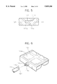
FIG. 1 is a perspective view for showing an embodiment of the conventional automatic ice maker. As illustrated in FIG. 1, a driving section (not shown) is disposed at the front portion of the ice making compartment, and a fixing member 41 which is protruded rearward and has an L-shape is disposed at one end of the rear portion of the driving section. In the driving section, a driving apparatus having a motor, a gear mechanism and an outputting shaft 20, is installed. The driving apparatus reduces the when another part is located within the rotating radius range of ice separating plate 15, the rotation becomes limited. Therefore, it is difficult to design the ice maker.
SUMMARY OF THE INVENTION
Accordingly, it is an object of the present invention considering the above-mentioned defects, to provide an automatic ice maker which can effectively separate ice from an ice tray after making the ice in a refrigerator.
To accomplish the above object, there is provided in the present invention an automatic ice maker of a refrigerator comprising an ice tray for freezing water and forming ice, the ice tray being provided with a first rotating shaft at a first end thereof and a second rotating shaft at a second end thereof which is opposite to the first end, a power transmitting means for transmitting a rotational force to the ice tray through the first rotating shaft and applying a compressive force along a direction of the first rotating shaft to separate the ice, a supporting means for limiting a rotation of the ice tray and supporting the second rotation shaft, and a driving means for providing the rotational force to the power transmitting means.
Preferably, the power transmitting means includes a first cylindrical connecting, member having a first inclined plane, a first-end of the first cylindrical connecting member being connected to the driving means and a second end of the first cylindrical connecting member, which is opposite to the first end, being connected to the first rotating shaft of the ice tray, and a second cylindrical connecting member having a second inclined plane corresponding to the first inclined plane for closely adhering to the first inclined plane, and having a central line which coincides with a central line of the first rotating shaft of the ice tray. At this time, a shaft hole into which the first rotating rotation speed of the motor by the gear mechanism and transmits the reduced rotation to outputting shaft 20.
In fixing member 41, an ice tray 10 is disposed. At the front center portion of ice tray 10, a rotating pin 11 is formed. The front center portion of rotating pin 11 is connected to and supported by outputting shaft 20 which receives the rotational force generated by the motor. In addition, at the rear center portion of ice tray 10, a supporting shaft 13 is formed. Ice tray 10 is rotatably fixed to fixing member 41 through supporting shaft 13. The rotational force generated by the motor is transmitted to outputting shaft 20 through the gear mechanism, and the rotational force is transmitted to ice tray 10 through rotating pin 11. Accordingly, ice tray 10 can be rotated by the rotation of outputting shaft 20.
Ice tray 10 is made from a material such as plastic which can be twisted laterally and ice tray 10 has a hexahedral shape of which upper surface is opened. The inside of ice tray 10 is partitioned into a plurality of concave (recessed) portions for making ice. The cross-section of the side portion of the concave portion has a reverse mesa shape for advantageously removing the ice from ice tray 10. Into ice tray 10, water is supplied by a water feeding apparatus.
At the rear portion of ice tray 10, that is, at one edge portion where supporting shaft 13 is formed, and ice separating plate 15 is formed along the length of ice tray 10. In addition, at one corner portion of fixing member 41, that is, at the corner portion opposite to ice separating plate 15 while centering supporting shaft 13 as a center, a stopper 31 is formed. Stopper 31 makes contact with ice separating plate 15 to limit the rotation of ice tray 10 when ice tray 10 is rotated to separate the ice in ice tray 10 from ice tray 10.
At the lower portion of the ice making compartment and below ice tray 10, an ice reservoir (not shown) is disposed. The separated ice through the rotation of ice tray 10 is stored in the ice reservoir.
FIG. 2 is a schematic diagram for explaining the ice separating process in the conventional automatic ice maker.
in the conventional automatic ice maker illustrated in FIG. 1, when the ice is obtained in the concave portion of ice tray 10, micom (not shown) senses the ice through a temperature sensor (not shown) provided in ice tray 10. When the microcomputer (hereinafter, referred to as "micron") judges that the ice is completely frozen, the micom provides an ice separating signal to the motor for driving the motor. The rotational force of the motor is transmitted to rotating pin 11 through outputting shaft 20 and ice tray 10 rotates to the degree of 180°, as illustrated in FIG. 2. At this time, ice separating plate 15 makes contact with stopper 31 for preventing further rotation of ice tray 10. However, the rotational force of the motor is still transmitted to ice tray 10 through rotating pin 11. Accordingly, the rear portion of ice tray 10 where ice separating plate 15 is formed cannot rotate further than the 180° rotated state. However, the front portion of ice tray 10 to which the rotational force of the motor is transmitted, that is, the portion where rotating pin 11 is formed, rotates further that the 180° rotated state to twist ice tray 10 laterally. Through the twist of ice tray 10, the ice formed in ice tray 10 is separated from ice tray 10 and falls down.
As described above, the conventional automatic ice maker includes the ice separating plate having a plate form or the stopper. However, the ice separating plate and the stopper are easily deformed or destroyed. The ice separating operation cannot be completely performed due to the deformation or the destruction of the parts. In addition, shaft is inserted, is formed at the second end of the first cylindrical connecting member. The second cylindrical connecting member is extrapolated around the first rotating shaft (that is, the first rotation shaft is surrounded by the second cylindrical connecting member) and the first rotating shaft is protruded from the second cylindrical connecting member.
Particularly, the supporting means rotatably supports the second rotating shaft to an inner wall of the refrigerator, the supporting means being provided with a first cylindrical supporting member in which a cross section of a free end portion is formed in a first spiral (or helical) shape for having a first stepped jaw for limiting a rotation of the ice tray, and a second cylindrical supporting member having a second stepped jaw corresponding to the first stepped jaw and having a second spiral shape corresponding to the first spiral shape. At this time, the first cylindrical supporting member includes a shaft hole into which the second rotating shaft is inserted, and the second cylindrical supporting member is extrapolated around the second rotating shaft (that is, the second rotating shaft is surrounded by the second cylindrical supporting member) the second rotating shaft being protruded from the second cylindrical supporting member.
According to the present invention, the rotating force of the step motor is transmitted to the power transmitting member through the driving section. The power transmitting member first provides the rotational force to the ice tray for turning over the ice tray. A compressive force is generated by the power transmitting member and applied to the turned-over (or up-side-down) ice tray to press the ice tray. By the pressing phenomena, the ice is separated from the ice tray.
BRIEF DESCRIPTION OF THE DRAWINGS
The above object and advantages of the present invention will become more apparent by describing in detail preferred embodiments thereof with reference to the attached drawings in which:
FIG. 1 is a perspective view for schematically showing the constitution of the conventional automatic ice maker;
FIG. 2 is a perspective view for schematically explaining the ice separating process of the conventional automatic ice maker;
FIG. 3 is a perspective view for showing the constitution of an automatic ice maker according to an embodiment of the present invention;
FIG. 4 is a cross-sectional view cut alone the central line of the automatic ice maker illustrated in FIG. 3;
FIG. 5 is a cross-sectional view of the power transmitting member of the automatic ice maker illustrated in FIG. 3;
FIG. 6 is a partial perspective view of the power transmitting member illustrated in FIG. 5;
FIG. 7 is a cross-sectional view of the supporting member of the automatic ice maker illustrated in FIG. 3; and
FIG. 8 is a partial perspective view of the supporting member illustrated in FIG. 7.
DESCRIPTION OF THE PREFERRED EMBODIMENT
Hereinafter, the constituting elements and the operating principles of the automatic ice maker according to the present invention, will be explained in more detail with reference to the accompanying drawings.
FIG. 3 is a perspective view for showing the constitution of the automatic ice maker according to an embodiment of the present invention, and FIG. 4 is a cross-sectional view cut along the central line of the automatic ice maker illustrated in FIG. 3.
The illustrated automatic ice maker includes a driving section, an ice tray, a power transmitting member and a supporting member.
At the front portion of the ice making compartment of a refrigerator, the driving section is installed and at one rear end portion of the driving section, a fixing member 141 which has an L-shape and is protruded rearward, is installed. The driving section includes a step motor 200 and gear mechanism 300. To gear mechanism 300, an outputting shaft is connected. The driving section reduces the rotation speed of step motor 200 by the gear mechanism and transmits the reduced rotation to the outputting shaft.
In fixing member 141, an ice tray 100 is disposed. A first rotating shaft 111b is formed at a first end which is the front portion of ice tray 110, and a second rotating shaft 112a is formed at a second end which is opposite to the first end. First rotating shaft 111b is connected to the outputting shaft of gear mechanism 300 of the driving section and transmits the rotational force of step motor 200 to ice tray 110.
Ice tray 110 has a plurality of concave (recessed) portions for freezing water to form ice. Ice tray 110 is made from a material such as plastic which can be laterally twisted and ice tray 110 has a hexahedral shape of which upper surface is opened. The inner portion of ice tray 110 is partitioned into a plurality of concave portions for making ice. The cross-section of the side portion of the concave portion has a reverse mesa shape for separating the ice from the ice tray advantageously. Into ice tray 110, water is supplied by an apparatus (not shown) for feeding ice making water.
At the front center portion of ice tray 110, the power transmitting member for firstly transmitting the rotational force to ice tray 110 through first rotating shaft 111b and for secondly transmitting a compressive force along the direction of the first rotating shaft to separate the ice, is disposed.
FIG. 5 is a cross-sectional view of the power transmitting member of the automatic ice maker illustrated in FIG. 3, and FIG. 6 is a partial perspective view of the power transmitting member illustrated in FIG. 5.
As illustrated in FIGS. 5 & 6, the power transmitting member includes a first cylindrical connecting member 120 and a second cylindrical connecting member 111. A first end of first cylindrical connecting member 120 is connected to the outputting shaft of gear mechanism, 300 for receiving the rotational force of step motor 200. A second end of the power transmitting member, which is opposite to the first end, is connected to first rotating shaft 111b of ice tray 110 and has an elliptical first inclined plane 121a. At the second end of first cylindrical connecting member 120, a shaft hole 121 into which first rotating shaft 111b is inserted, is formed.
Second cylindrical connecting member 111 has a second inclined plane 111a corresponding to first inclined plane 121a for adhering closely to first inclined plane 121a and had a central line which coincides with the central line of first rotating shaft 111b of ice tray 110. Second cylindrical connecting member 111 is extrapolated around the first rotating shaft 111b (that is, first rotation shaft 111b is surrounded by second cylindrical connecting member 111) and first rotating shaft 111b is protruded from second cylindrical connecting member 111.
The rotational force generated from step motor 200 is transmitted to first cylindrical connecting member 120 through the outputting shaft, and the rotational force is again transmitted to first rotating shaft 111b of ice tray 110 through second cylindrical connecting member 111. Since first inclined plane 121a of first cylindrical connecting member 120 and second inclined plane 111a of second cylindrical connecting member 111 adhere closely to each other, the rotational force of first cylindrical connecting member 120 is transmitted to ice tray 110 to thereby rotate ice tray 110.
When second cylindrical connecting member 111 does not rotate, while first cylindrical connecting member 120 rotates, first inclined plane 121a and second inclined plane 111a generate the horizontal pushing (pressing) force (i.e. lateral (or horizontal) compressive force) and transmit this force to ice tray 110.
The supporting member limits the rotation of ice tray 110 and supports second rotating shaft 112a. FIG. 7 is a cross-sectional view of the supporting member of the automatic ice maker illustrated in FIG. 5, and FIG. 8 is a partial perspective view of the supporting member illustrated in FIG. 7.
Referring to FIGS. 7 & 8, the supporting member includes a first cylindrical supporting member 133 and a second cylindrical supporting member 112. First cylindrical supporting member 133 rotatably supports second rotating shaft 112a to the inner wall of the refrigerator. The cross section of the free end of first cylindrical supporting member 133 is formed in a first spiral shape so that first cylindrical supporting member 133 has a first stepped jaw 133b. Second cylindrical supporting member 112 has a second stepped jaw 112b corresponding to first stepped jaw 133b and a second spiral shape corresponding to the first spiral shape.
First stepped jaw 133b and second stepped jaw 112b are positioned symmetrically while centering second rotating shaft 112a as a center while freezing water contained in the concave portion. When the rotational force of step motor 200 is transmitted to ice tray 110 through the power transmitting member for separating the ice formed in the concave portions of ice tray 110, ice tray 110 rotates. At the position where ice tray 110 rotates to the degree of 180°, first stepped jaw 133b comes into contact with second stepped jaw 112b and ice tray 110 cannot be rotated further.
At this time, second cylindrical connecting member 111 does not rotate, while first cylindrical connecting member 120 rotates. Accordingly, first inclines plane 121a and second inclined plane 111a generate lateral pushing forces (i.e. lateral compressive force). This compressive force is transmitted to ice in the ice tray 110 to separate the ice from ice tray 110.
First cylindrical supporting member 133 has shaft hole 133a into which second rotating shaft 112a is inserted. Second cylindrical supporting member 112 is extrapolated around second rotating shaft 112a (that is, second rotating shaft 112a is surrounded by second cylindrical supporting member 112) and second rotating shaft 112a is protruded from second cylindrical supporting member 112.
First stepped jaw 133b comes into contact with second stepped jaw 112b to limit the rotation of ice tray 110 when ice tray 110 rotates for separating the ice from ice tray 110.
An ice reservoir (not shown) is disposed at the bottom portion of the ice making compartment, under ice tray 110. The ice separated through the rotation of ice tray 110 is stored in the ice reservoir.
The operation of the automatic ice maker as described above, will be explained below, in detail.
At the state illustrated in FIG. 3, water is supplied to the concave portions of ice tray 110 through the water feeding apparatus. Second rotating shaft 112a of ice tray 110 is rotatably inserted in shaft hole 133a of first cylindrical supporting member 133 which is fixed to the inner surface of L-shaped fixing member 141 which is fixed to the inner wall of the refrigerator. In addition, first rotating shaft 111b of ice tray 110 is inserted into shaft hole 121 of first cylindrical connecting member 120.
At this time, second stepped jaw 112b of the spiral cross section of second rotating shaft 112a is positioned at the upper portion and first stepped jaw 133b of first cylindrical supporting member 133 is positioned at the lower portion. (Alternatively, they could be positioned at the contrary positions. In this case, first stepped jaw 133b and second stepped jaw 112b should be symmetrically positioned while centering second rotating shaft 112a as a center.) In addition, second inclined plane 111a of second cylindrical connecting member 111 closely make contact with first inclined plane 121a of first cylindrical connecting member 120.
When the ice is formed, a micom (not shown) senses the ice through a temperature sensor (not shown) provided in ice tray 110. When the micom judges that the ice is completely frozen, micom provides an ice separating signal through a controlling section 400 to step motor 200 to drive step motor 200.
The rotational force of step motor 200 is transmitted to first cylindrical connecting member 120 through the driving section. At this time, first cylindrical member 120 and first rotating shaft 111b are idling. However, second inclined plane 111a of second cylindrical connecting member 111 closely makes contact with first inclined plane 121a of first cylindrical connecting member 120. Therefore, the rotational force of second cylindrical connecting member 111 is transmitted to first rotating shaft 111b to rotate ice tray 110.
When ice tray 110 rotates to the degree of 180°, first stepped jaw of first supporting member 133 and second stepped jaw 112b of second supporting member 112 meet each other so that ice tray 110 cannot be rotated further. At this time, ice tray 110 is in the state of being turned-over to the degree of 180°.
However, controlling section 400 controls step motor 200 for continuing the rotation. Then, ice tray 110 keeps the turned-over state by first stepped jaw 133b of first supporting member 133 and second stepped jaw 112b of second supporting member 112. Second inclined plane 111a of second cylindrical connecting member 111 and first inclined plane 121a of first cylindrical connecting member 120 make a hysterisis, and parts of them make contact to generate the compressive force. This compressive force is transmitted to ice tray 110. That is, the rotating movement of step motor 200 is transformed into a linear movement by second inclined plane 111a of second cylindrical connecting member 111 and first inclined plane 121a of first cylindrical connecting member 120.
Accordingly, turned-over ice tray 110 to the degree of 180° receives the lateral compressive force and is twisted. Through the twist, ice formed in ice tray 110 moves to make a space between ice tray 110 and the ice. As a result, ice is separated from ice tray 110.
The separated ice falls into the ice reservoir disposed under ice tray 110 and is stored.
According to the present invention, the rotational force of the step motor is transmitted to the power transmitting member. The power transmitting member firstly transmits the rotational force to the ice tray to turn over the ice tray to the degree of 180°. The turned-over ice tray cannot rotate further. At this time, the step motor continues the rotation and the power transmitting member generates the compressive force to transmit to the ice tray. Accordingly, the ice tray receives the lateral compressive force and is twisted. Through the twist, the ice in the ice tray moves to make a space between the ice tray and the ice. Then the ice is separated from the ice tray.
In the automatic ice maker of the present invention, the power transmitting apparatus for providing the rotational force and the lateral compressive force to the rotating shaft, is formed. The manufacturing of the ice maker is advantageous and the space used for designing thereof is reduced to increase a free space. In addition, the supporting member for limiting the rotation of the ice tray if formed around the fixing shaft to increase a firmness.
Although the preferred embodiments of the invention has been described, it is understood that the present invention should not be limited to the preferred embodiment, but various changes and modifications can be made by one skilled in the art within the spirit and scope of the invention as hereinafter claimed.

Claims (7)

What is claimed is:
1. An automatic ice maker of a refrigerator comprising:
an ice tray for freezing water and forming ice, said ice tray being provided with a first rotating shaft at a first end thereof and a second rotating shaft at a second end thereof which is opposite to the first end;
a power transmitting means for transmitting a rotational force to said ice tray through said first rotating shaft and transmitting a compressive force along a direction of said first rotating shaft to separate the ice;
a supporting means for limiting a rotation of said ice tray and supporting said second rotating shaft; and
a driving means for providing the rotational force to said power transmitting means, wherein said power transmitting means includes a first cylindrical connecting member having a first inclined plane, a first end of said first cylindrical connecting member being connected to said driving means and a second end of said first cylindrical connecting member, which is opposite to the first end, being connected to a first rotating shaft of said ice tray, and a second cylindrical connecting member having a second inclined plane corresponding to the first inclined plane for closely adhering to the first inclined plane and having a central line which coincides with a central line of said first rotating shaft of said ice tray.
2. An automatic ice maker of a refrigerator as claimed in claim 1, wherein a shaft hole to which said first rotating shaft is inserted, is formed at said second end of said first cylindrical connecting member.
3. An automatic ice maker of a refrigerator as claimed in claim 1, wherein said second cylindrical connecting member is extrapolated around said first rotating shaft and said first rotating shaft is protruded from said second cylindrical connecting member.
4. An automatic ice maker of a refrigerator as claimed in claim 1, wherein said power transmitting means transmits the rotational force to said ice tray to turn over said ice tray, and transmits the lateral compressive force in said turned-over ice tray to separate said ice from said ice tray.
5. An automatic ice maker of a refrigerator, comprising:
an ice tray for freezing water and forming ice, said ice tray being provided with a first rotating shaft at a first end thereof and a second rotating shaft at a second end thereof which is opposite to the first end:
a power transmitting means for transmitting a rotational force to said ice tray through said first rotating shaft and transmitting a compressive force along a direction of said first rotating shaft to separate the ice;
a supporting means for limiting a rotation of said ice tray and supporting said second rotating shaft; and
a driving means for providing the rotational force to said power transmitting means, wherein said supporting means rotatably supports said second rotation shaft to an inner wall of the refrigerator, said supporting means being provided with a first cylindrical supporting member in which a cross-section of a free end portion is formed in a first spiral shape for having a first stepped jaw for limiting a rotation of said ice tray and a second cylindrical supporting member having a second stepped jaw corresponding to said first stepped jaw and having a second spiral shape corresponding to said first spiral shape.
6. An automatic ice maker of a refrigerator as claimed in claim 5, wherein said second stepped jaw is formed at a position symmetric to said second stepped jaw while centering second rotating shaft as a center.
7. An automatic ice maker of a refrigerator as claimed in claim 5, wherein said first cylindrical member includes a shaft hole to which said second rotating shaft is inserted and said second cylindrical supporting member is extrapolated around said second rotating shaft, said second rotating shaft being protruded from said second cylindrical supporting member.
US08/865,707 1996-08-31 1997-05-30 Automatic ice maker of a refrigerator Expired - Fee Related US5829266A (en)

Applications Claiming Priority (2)

Application Number Priority Date Filing Date Title
KR96-37760 1996-08-31
KR1019960037760A KR100202064B1 (en) 1996-08-31 1996-08-31 Ice making machine ice making machine

Publications (1)

Publication Number Publication Date
US5829266A true US5829266A (en) 1998-11-03

Family

ID=19472463

Family Applications (1)

Application Number Title Priority Date Filing Date
US08/865,707 Expired - Fee Related US5829266A (en) 1996-08-31 1997-05-30 Automatic ice maker of a refrigerator

Country Status (4)

Country Link
US (1) US5829266A (en)
JP (1) JPH1089819A (en)
KR (1) KR100202064B1 (en)
CN (1) CN1104611C (en)

Cited By (11)

* Cited by examiner, † Cited by third party
Publication number Priority date Publication date Assignee Title
US6481235B2 (en) * 2000-08-07 2002-11-19 Lg Electronics Inc. Ice making device of refrigerator
US6571567B2 (en) * 2001-09-07 2003-06-03 Lg Electronics Inc. Ice-making apparatus in refrigerator
US20050196522A1 (en) * 2000-12-21 2005-09-08 Price Joseph K. System capable of determining applied and anodized coating thickness of a coated-anodized product
US20050241329A1 (en) * 2004-04-07 2005-11-03 Castrellon Martha A A Ice cube making device for refrigerators
US20070209381A1 (en) * 2006-03-13 2007-09-13 Japan Servo Co., Ltd. Automatic icemaker
US20100101261A1 (en) * 2007-02-12 2010-04-29 Jong-Seok Yoon Ice making device and refrigerator
US20100229590A1 (en) * 2006-06-07 2010-09-16 Whirlpool Corporation Ice Maker
US20100236273A1 (en) * 2006-06-29 2010-09-23 Lg Electronics Inc. Ice making device for refrigerator
US20100269532A1 (en) * 2007-12-14 2010-10-28 Lg Electronics Inc. Ice-making assembly of refrigerator
US20120247130A1 (en) * 2011-03-29 2012-10-04 Nidec Sankyo Corporation Ice making device and its control method
US20160131406A1 (en) * 2013-05-28 2016-05-12 W. Schoonen Beheer B.V. Ice cube maker

Families Citing this family (24)

* Cited by examiner, † Cited by third party
Publication number Priority date Publication date Assignee Title
CN100337075C (en) * 2003-04-11 2007-09-12 乐金电子(天津)电器有限公司 Ice-making container made of double material
DE20318710U1 (en) * 2003-12-03 2004-02-26 BSH Bosch und Siemens Hausgeräte GmbH Stückeisbehälter
CN100458327C (en) * 2004-07-08 2009-02-04 乐金电子(天津)电器有限公司 Combining structure of automatic ice making machine of refrigerator
JP4262694B2 (en) * 2005-04-22 2009-05-13 日立アプライアンス株式会社 Automatic ice making device and refrigerator equipped with automatic ice making device
KR100808171B1 (en) * 2005-12-16 2008-03-03 엘지전자 주식회사 Ice maker and control method
KR100705182B1 (en) * 2006-05-29 2007-04-09 엘지전자 주식회사 Ice Tray Assembly For Refrigerator
KR100863389B1 (en) * 2006-08-24 2008-10-13 엘지전자 주식회사 Refrigerators and refrigerators
CN101311650B (en) * 2007-05-23 2010-10-06 海尔集团公司 Snap-in device for ice-making container
CN101349492B (en) * 2007-07-19 2011-01-12 海尔集团公司 Deicing apparatus of ice making machine
US20110146324A1 (en) 2009-12-22 2011-06-23 Lg Electronics Inc. Refrigerator
KR101631322B1 (en) * 2009-12-22 2016-06-24 엘지전자 주식회사 Refrigerator
CN101871710B (en) * 2010-07-08 2012-11-28 合肥美的荣事达电冰箱有限公司 Ice-making motor assembly and automatic ice machine
CN102221276B (en) * 2011-05-17 2013-01-09 合肥美的荣事达电冰箱有限公司 Ice making device for refrigerator and refrigerator with same
CN102305507B (en) * 2011-06-08 2013-05-22 合肥美的荣事达电冰箱有限公司 Automatic ice maker and refrigerator with the same
CN102305510B (en) * 2011-06-08 2013-05-22 合肥美的荣事达电冰箱有限公司 Drives for automatic ice makers, automatic ice makers and refrigerators
CN102305508B (en) * 2011-06-08 2013-05-22 合肥美的荣事达电冰箱有限公司 Drives for automatic ice makers, automatic ice makers and refrigerators
CN102278842B (en) * 2011-09-02 2013-04-17 合肥美的荣事达电冰箱有限公司 Manual ice maker and refrigerator
CN104165489B (en) * 2014-09-10 2017-02-15 合肥晶弘电器有限公司 Eccentric ice maker and refrigerator
EP3447421B1 (en) * 2016-07-28 2021-05-26 Dae Chang Co., Ltd. Ice-making apparatus and refrigerator comprising same
CN106839554A (en) * 2017-02-13 2017-06-13 合肥华凌股份有限公司 A kind of ice maker and refrigerator
CN107192186A (en) * 2017-05-22 2017-09-22 合肥华凌股份有限公司 A kind of manual ice maker and refrigerator
JP6902435B2 (en) 2017-08-31 2021-07-14 日本電産サンキョー株式会社 Ice maker
CN113091370B (en) * 2019-12-23 2022-09-23 青岛海尔电冰箱有限公司 Refrigerator and control method thereof
CN115451629B (en) * 2022-09-22 2024-10-25 海信冰箱有限公司 refrigerator

Citations (7)

* Cited by examiner, † Cited by third party
Publication number Priority date Publication date Assignee Title
US1894897A (en) * 1931-06-29 1933-01-17 Gen Utilities Mfg Co Ice tray
US2613511A (en) * 1948-04-14 1952-10-14 Flakice Corp Ice-making machine
US3330128A (en) * 1966-05-11 1967-07-11 American Motors Corp Ice cube making and dispensing device
US5177980A (en) * 1990-04-26 1993-01-12 Kabushiki Kaisha Toshiba Automatic ice maker of refrigerators
US5253487A (en) * 1989-11-15 1993-10-19 Kabushiki Kaisha Toshiba Automatic ice maker and household refrigerator equipped therewith
US5400605A (en) * 1994-02-15 1995-03-28 Samsung Electronics Co., Ltd. Ice maker control method
US5425248A (en) * 1994-06-27 1995-06-20 General Electric Company Ice maker subassembly for a refrigerator freezer

Patent Citations (7)

* Cited by examiner, † Cited by third party
Publication number Priority date Publication date Assignee Title
US1894897A (en) * 1931-06-29 1933-01-17 Gen Utilities Mfg Co Ice tray
US2613511A (en) * 1948-04-14 1952-10-14 Flakice Corp Ice-making machine
US3330128A (en) * 1966-05-11 1967-07-11 American Motors Corp Ice cube making and dispensing device
US5253487A (en) * 1989-11-15 1993-10-19 Kabushiki Kaisha Toshiba Automatic ice maker and household refrigerator equipped therewith
US5177980A (en) * 1990-04-26 1993-01-12 Kabushiki Kaisha Toshiba Automatic ice maker of refrigerators
US5400605A (en) * 1994-02-15 1995-03-28 Samsung Electronics Co., Ltd. Ice maker control method
US5425248A (en) * 1994-06-27 1995-06-20 General Electric Company Ice maker subassembly for a refrigerator freezer

Cited By (21)

* Cited by examiner, † Cited by third party
Publication number Priority date Publication date Assignee Title
US6481235B2 (en) * 2000-08-07 2002-11-19 Lg Electronics Inc. Ice making device of refrigerator
US20050196522A1 (en) * 2000-12-21 2005-09-08 Price Joseph K. System capable of determining applied and anodized coating thickness of a coated-anodized product
US6571567B2 (en) * 2001-09-07 2003-06-03 Lg Electronics Inc. Ice-making apparatus in refrigerator
US20030192327A1 (en) * 2001-09-07 2003-10-16 Si Yeon An Ice-making apparatus in refrigerator
US6901764B2 (en) * 2001-09-07 2005-06-07 Lg Electroincs Inc. Ice-making apparatus in refrigerator
US20050241329A1 (en) * 2004-04-07 2005-11-03 Castrellon Martha A A Ice cube making device for refrigerators
US7204092B2 (en) 2004-04-07 2007-04-17 Mabe Mexico S.De R.L De C.V. Ice cube making device for refrigerators
US20070180845A1 (en) * 2004-04-07 2007-08-09 Azcarate Castrellon Martha A Ice cube making device for refrigerators
US7386993B2 (en) 2004-04-07 2008-06-17 Mabe Mexico S. De R.L. De C.V. Ice cube making device for refrigerators
US7845180B2 (en) * 2006-03-13 2010-12-07 Japan Servo Co., Ltd. Automatic icemaker
US20070209381A1 (en) * 2006-03-13 2007-09-13 Japan Servo Co., Ltd. Automatic icemaker
US20100229590A1 (en) * 2006-06-07 2010-09-16 Whirlpool Corporation Ice Maker
US8104304B2 (en) 2006-06-29 2012-01-31 Lg Electronics Inc. Ice making device for refrigerator
US20100236273A1 (en) * 2006-06-29 2010-09-23 Lg Electronics Inc. Ice making device for refrigerator
US20100101261A1 (en) * 2007-02-12 2010-04-29 Jong-Seok Yoon Ice making device and refrigerator
US8726686B2 (en) * 2007-02-12 2014-05-20 Lg Electronics Inc. Ice making device and refrigerator
US20100269532A1 (en) * 2007-12-14 2010-10-28 Lg Electronics Inc. Ice-making assembly of refrigerator
US20120247130A1 (en) * 2011-03-29 2012-10-04 Nidec Sankyo Corporation Ice making device and its control method
US9032746B2 (en) * 2011-03-29 2015-05-19 Nidec Sankyo Corporation Ice making device and control method using electrostatic capacitance
US20160131406A1 (en) * 2013-05-28 2016-05-12 W. Schoonen Beheer B.V. Ice cube maker
US10386105B2 (en) * 2013-05-28 2019-08-20 W. Schoonen Beheer B.V. Ice cube maker

Also Published As

Publication number Publication date
KR19980017938A (en) 1998-06-05
JPH1089819A (en) 1998-04-10
KR100202064B1 (en) 1999-06-15
CN1104611C (en) 2003-04-02
CN1175678A (en) 1998-03-11

Similar Documents

Publication Publication Date Title
US5829266A (en) Automatic ice maker of a refrigerator
US7111473B2 (en) Ice bank of ice-making device for refrigerator
KR0169439B1 (en) Refrigerator Ice Maker
US12078402B2 (en) Ice maker and refrigerator
US12449174B2 (en) Ice maker for refrigerator
US6044658A (en) Automatic ice making apparatus for use in a refrigerator
EP4336130A1 (en) Home appliance with an ice maker
US7360377B2 (en) Refrigerator
KR100221143B1 (en) Refrigerator Automatic Ice Maker
KR20000011102U (en) Ice machine of refrigerator automatic ice maker
EP0937954B1 (en) Ice-cube releasing apparatus
EP3653961B1 (en) Ice maker and refrigerator
KR20000007731U (en) Ice Separator in Automatic Refrigerator
KR102835704B1 (en) Ice maker and refrigerator including the same
KR0176944B1 (en) Shaved ice dispense in the refrigerator
KR200342122Y1 (en) Automatic ice-discharging apparatus for refrigerators
JPH06331244A (en) Refrigerator equipped with automatic ice making device
KR100683409B1 (en) Refrigerator
KR100526208B1 (en) Ice maker
KR20020012442A (en) The regulatory structure and method of the amount of storaged ice for refrigerators
KR19990004815A (en) Ice Molding Apparatus and Method for Automatic Ice Maker
JP2002295932A (en) Automatic ice making equipment
JPH0526548A (en) Refrigerator with automatic ice-making device
KR20000007727U (en) Ice machine of refrigerator automatic ice maker using hot wire
KR20030030677A (en) Device for supporting ice maker for refrigerator

Legal Events

Date Code Title Description
AS Assignment

Owner name: DAEWOO ELECTRONICS CO., LTD., KOREA, REPUBLIC OF

Free format text: ASSIGNMENT OF ASSIGNORS INTEREST;ASSIGNOR:LYU, GANG;REEL/FRAME:008668/0297

Effective date: 19970529

FEPP Fee payment procedure

Free format text: PAYOR NUMBER ASSIGNED (ORIGINAL EVENT CODE: ASPN); ENTITY STATUS OF PATENT OWNER: LARGE ENTITY

FPAY Fee payment

Year of fee payment: 4

AS Assignment

Owner name: DAEWOO ELECTRONICS CORPORATION, KOREA, REPUBLIC OF

Free format text: ASSIGNMENT OF ASSIGNORS INTEREST;ASSIGNOR:DAEWOO ELECTRONICS CO., LTD.;REEL/FRAME:013645/0159

Effective date: 20021231

REMI Maintenance fee reminder mailed
LAPS Lapse for failure to pay maintenance fees
STCH Information on status: patent discontinuation

Free format text: PATENT EXPIRED DUE TO NONPAYMENT OF MAINTENANCE FEES UNDER 37 CFR 1.362

FP Lapsed due to failure to pay maintenance fee

Effective date: 20061103