US5823239A - Work bench - Google Patents
Work bench Download PDFInfo
- Publication number
- US5823239A US5823239A US08/875,397 US87539797A US5823239A US 5823239 A US5823239 A US 5823239A US 87539797 A US87539797 A US 87539797A US 5823239 A US5823239 A US 5823239A
- Authority
- US
- United States
- Prior art keywords
- base
- bracket
- work piece
- fence
- carriage
- Prior art date
- Legal status (The legal status is an assumption and is not a legal conclusion. Google has not performed a legal analysis and makes no representation as to the accuracy of the status listed.)
- Expired - Fee Related
Links
- 238000005520 cutting process Methods 0.000 claims description 18
- 230000013011 mating Effects 0.000 claims 3
- 210000003414 extremity Anatomy 0.000 description 4
- 230000007935 neutral effect Effects 0.000 description 3
- 238000000034 method Methods 0.000 description 2
- 239000002023 wood Substances 0.000 description 2
- 230000004308 accommodation Effects 0.000 description 1
- 229910052782 aluminium Inorganic materials 0.000 description 1
- XAGFODPZIPBFFR-UHFFFAOYSA-N aluminium Chemical compound [Al] XAGFODPZIPBFFR-UHFFFAOYSA-N 0.000 description 1
- 210000003141 lower extremity Anatomy 0.000 description 1
- 239000000463 material Substances 0.000 description 1
- 229910052751 metal Inorganic materials 0.000 description 1
- 239000002184 metal Substances 0.000 description 1
- 238000012986 modification Methods 0.000 description 1
- 230000004048 modification Effects 0.000 description 1
- 238000007493 shaping process Methods 0.000 description 1
Images


Classifications
-
- B—PERFORMING OPERATIONS; TRANSPORTING
- B27—WORKING OR PRESERVING WOOD OR SIMILAR MATERIAL; NAILING OR STAPLING MACHINES IN GENERAL
- B27F—DOVETAILED WORK; TENONS; SLOTTING MACHINES FOR WOOD OR SIMILAR MATERIAL; NAILING OR STAPLING MACHINES
- B27F1/00—Dovetailed work; Tenons; Making tongues or grooves; Groove- and- tongue jointed work; Finger- joints
- B27F1/08—Making dovetails, tongues, or tenons, of definite limited length
- B27F1/12—Corner- locking mechanisms, i.e. machines for cutting crenellated joints
-
- B—PERFORMING OPERATIONS; TRANSPORTING
- B27—WORKING OR PRESERVING WOOD OR SIMILAR MATERIAL; NAILING OR STAPLING MACHINES IN GENERAL
- B27C—PLANING, DRILLING, MILLING, TURNING OR UNIVERSAL MACHINES FOR WOOD OR SIMILAR MATERIAL
- B27C5/00—Machines designed for producing special profiles or shaped work, e.g. by rotary cutters; Equipment therefor
- B27C5/02—Machines with table
- B27C5/04—Guide fences for work
Definitions
- This invention relates to work benches for cutting pieces of wood, plastic and other material. More particularly the invention relates to a work bench equipped with a jig or fence having means by which a piece of work may be maintained in a wide variety of different positions. Such means facilitates the cutting of the work piece. The invention also relates to a work bench having a router mounted for sliding beneath a stationary table top.
- a shortcoming of many such work benches is that they usually are not capable of maintaining a piece of work in the correct position throughout the cutting operation. During cutting the piece of work may deviate from the correct position by reason of warps, knots and other imperfections in the work piece. Heavier work pieces are especially difficult to guide accurately through the cutter because they are awkward to handle. An inaccurate cut is the usual result where the work piece deviates from the correct position during cutting and this result is particularly troublesome where the cutter is a router.
- An object of another aspect of the invention is to provide a work bench having a jig or fence which may be maintained in a wide variety of different positions.
- the work bench is as a result particularly suitable for cutting dovetails and pins or tenons and mortises in a piece of work.
- the first object is accomplished by a router table including: a table having a stationary planar upper surface and an elongated slot formed therein; a fence which is adjustably mounted on the upper surface and to which a work piece may be clamped such that the work piece may be adjustably positioned on the upper surface and maintained immovable in a desired position during the routing operation; a carriage slideably mounted beneath the upper surface; and a router mounted to the carriage and having a bit which extends through the slot and projects upwardly of the upper surface to engage the work piece, the bit cutting out an elongated groove in the immovable work piece as the carriage slides beneath the upper surface.
- the second object is accomplished by a fence having a base which is rotatably mounted to the upper surface of a work bench table; first adjustment means for selectively preventing the base from rotating with respect to the upper surface; a bracket slideably mounted to the base and having an elongated wall to which the work piece may be clamped; and second adjustment means for selectively fixing the bracket to the base for preventing the bracket from sliding relative thereto.
- FIG. 1 is a perspective view of the router table according to the invention
- FIG. 2 is a fragmentary perspective view, in enlarged scale, of a mechanism for adjusting the position of a piece of work on the fence;
- FIG. 3 is a plan view, in enlarged scale, of the central panel of the router table
- FIG. 4 is a view of the lower wall of the base of the fence, in enlarged scale
- FIG. 5 is an elevation of the bracket and base of the fence, in enlarged scale, from the rear of the router table;
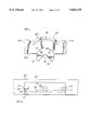
- FIG. 6 is a perspective view of the carriage, in enlarged scale, together with a portion of the top of the table;
- FIG. 7 is an elevation of the carriage from the front together with a portion of the table top
- FIG. 8 is an elevation of the carriage from one side
- FIGS. 9, 10 and 11 are plan views of the central panel of the router table showing the manner in which a dovetail pin having non-parallel side walls is formed in a piece of work;
- FIGS. 12 and 13 are perspective views of the fence and a work piece showing the manner in which a number of mortises having side walls which are parallel to each other is formed in a piece of work.
- the router table of the invention is indicated by the numeral 10 and includes a stationary top 12 and four legs 14.
- the legs extend downwardly from the top and are interconnected adjacent to their lower ends by horizontal braces 16 to reduce undesirable movement of one leg relative to another.
- the table top is composed of three panels 18a, b and c which are disposed side by side and which have co-planar upper surfaces.
- the outer panels 18a, c are preferably composed of wood and the legs are connected to them while the intermediate panel 18b is composed of metal, preferably aluminum.
- a fence generally 20 is mounted upon the upper surface 21 of the table and a bit 22 of the router extends through a slot 24 formed in the intermediate panel 18b of the table.
- the fence includes a base 26 which rests upon the upper surface of the table.
- the base has parallel side edges 26a, b, a rear edge 26c and a forward edge 26d.
- the rear edge has a curved intermediate portion 28 and the forward edge is straight.
- a disc 30 is fastened to the downward facing surface of the base by means of screws 31.
- the disc is received in a conforming circular opening 32 in the table top.
- the diameter of the opening is slightly larger than the diameter of the disc so that the disc may freely rotate in the opening but not move laterally or forward and backward in it.
- the disc and the base to which it is attached rotate about a vertical axis 34 on which the center of the disc and the opening lie.
- a segment 36 is removed from the disc at its forward end to provide clearance for the bit. As well, shavings produced during the routing operation may fall to the floor through the opening in the disc. The shavings will accordingly not collect on the table and interfere with the operation.
- An arc-shaped slot 38 is formed in the base for receipt of a threaded stud 40.
- the lower end of the stud is tightened into a threaded opening in the table top.
- the stud projects upwardly through the slot and its upper end mates threadably with the threaded bore of a first adjustment means in the form of a handle 41.
- Rotation of handle 41 in one direction causes it to move downward into contact with the upper wall of the base and prevents the base from rotating relative to the table top.
- Rotation of the handle in the opposite direction allows the base to rotate relative to the table top.
- a U-shaped bracket 42 is mounted upon the base.
- the bracket is provided with a pair of longitudinally extending grooves 43 on each side thereof for accommodation of rails 44 formed on the upper surface of the base.
- the rails and grooves cooperate with one another to permit the bracket to slide but not rotate relative to the base.
- the bracket has a central web 45 which extends between a pair of flanges 46, 48.
- An elongated opening 50, 52 is formed in each flange.
- the openings are parallel to one another and receive threaded studs 54, 56.
- the studs are tightened into threaded openings in the base and their upper ends are threadably received in the bores of second adjustment means in the form of knobs 58, 59.
- knobs Like handle 41, rotation of the knobs in one direction causes the knobs to move downward or tighten into contact with the upper wall of the bracket while rotation in the opposite direction causes the knobs to loosen and to permit the bracket to slide relative to the base.
- An elongated angle member 60 is attached integrally to the bracket so that it too may slide but not rotate relative to the base.
- the lower limb 60a of the angle member rests on the upper surface of the table while its upstanding limb 60b serves as a surface to which a work piece may be clamped.
- the clamps may be conventional C-clamps which are not illustrated but are well known to those familiar with the art.
- a slot 61 is formed in the angle member for receipt of bit 22.
- a number of threaded apertures 62 are spaced horizontally along limb 60b.
- a locating block 64 rests on the table top and abuts the limb.
- the block is provided with a first locking means in the form of a threaded indexing pin 66 which extends through the block and into a selective aperture 62.
- the block is also provided with a second locking means in the form of an adjusting pin 68 which has a threaded outer wall and which is received in slot 70.
- Block 64 has a lateral surface 72 offset from the vertical along which a sliding block 74 moves. That block has an elongated flange 76 which is received in a conforming groove 78 formed in the block. A lateral surface 80 of the sliding block contacts a lateral surface 72 of the block.
- Adjusting pin 68 is provided for fixing the block in the required position.
- a gauge 84 is imprinted on the outer wall of the sliding block for indicating the position of surface 82 relative to the locating block.
- a carriage 90 to which a router 91 is mounted has a flat horizontally extending central plate 92.
- a bar 93 extends downward from the central plate and a horizontally extending handle 94 is provided for moving the carriage.
- Lateral portions 96, 98 are integrally connected to the side edges of the central plate. Each lateral portion is the same as the other and only one, namely 96 will be described. That lateral portion commences at an inner wall 100 which extends vertically downward from a side edge of the central plate and terminates at a lower wall 102. The latter wall extends horizontally outward and terminates at an outer wall 104 and the outer wall extends upward and terminates at an upper horizontal wall 106. The upper wall extends parallel to but is spaced apart from the lower wall 102 and terminates at an edge 108 which faces and is spaced apart from inner wall 100.
- a pair of rollers 110, 112 are mounted for rotation in the space between the lower and upper walls 102, 106.
- Each roller has lower and upper circular portions 114, 116 separated by a central portion 118 of larger diameter.
- the roller runs in the groove 120 of a track 122.
- the track runs parallel to the longitudinal axis of slot 24.
- the tracks are integral with the central panel 18b of the table and run adjacent to slot 24 along its entire length.
- An enlarged distal section 132 extends downward from one of the lateral edges of the central panel.
- a T-shaped slot 134 is formed in that section and the slot extends longitudinally along the entire length of the assembly i.e. from its front to its rear walls.
- a pair of conventional T nuts 136, 138 are slideably received in the slot.
- the nuts are located in front of and behind the carriage and serve as adjustable stops to limit its length of travel. The position of the nuts can be moved by loosening knobs 140, 141.
- Permanent stop means 142, 143 are connected at opposite ends of the slot for preventing the adjustable stops from sliding out of the slot.
- a flange 150 is formed on the side of the assembly opposite the T slot.
- the flange extends downward and terminates at a U-shaped bracket 152.
- the bracket is connected to a bar 154 and that bar is received between the jaws of an underhanging element 156.
- the latter element is attached to central plate 92 of the carriage.
- a threaded stud 158 passes through openings in the two jaws and a knob 160 facilitates turning of the stud to open and close the jaws. When the jaws are closed bar 154 is squeezed between them thereby preventing the carriage from moving.
- the procedure for cutting a dovetail pin in a piece of work is described with reference to FIGS. 9 to 11.
- the work piece 161 is clamped to the limb 60b of the fence so that the center line 162 of the dovetail pin to be cut is on the line of travel of bit 22.
- Handle 41 is then loosened to allow the base of the fence to rotate until, as illustrated in FIG. 10, the bit is in position to make the required cut in the work piece.
- Gauge 166 on the upper wall of the table top is provided so that the angle that the base is rotated from the neutral position can be ascertained.
- the base is in the neutral position in FIG. 9.
- Handle 41 is then tightened so that the work piece is held stationary and the bit is advanced by means of handle 94 to make the required first cut.
- the pin from the foregoing operation will have oppositely facing side walls 168a,b which are symmetrically disposed about the longitudinal axis 170 of the pin.
- the width of the dovetail pin can be adjusted by means of knobs 58, 59. Should a thinner pin be desired, the knobs are loosened to allow the fence to be moved toward the rear edge 172 of the table. Movement of the fence toward the forward edge 174 of the table will result in a wider pin.
- Fence 178 is provided with a short bar 180 adjacent to slot 182.
- the cross-section of the bar is preferably slightly less than the cross-section of the cut which is made in work piece 184 by the bit 186.
- the work piece is first clamped to the fence and a mortise is cut in it.
- the work piece is then moved to the left and the bar is inserted in the mortise as illustrated in FIG. 13 and a second mortise 190 is cut in the work piece.
- the operation can be repeated if additional mortises are to be cut into the work piece.
- Bar 180 ensures that the spacing between adjacent mortises remains uniform.
Landscapes
- Life Sciences & Earth Sciences (AREA)
- Engineering & Computer Science (AREA)
- Mechanical Engineering (AREA)
- Wood Science & Technology (AREA)
- Forests & Forestry (AREA)
- Milling, Drilling, And Turning Of Wood (AREA)
- Machines For Laying And Maintaining Railways (AREA)
- Dovetailed Work, And Nailing Machines And Stapling Machines For Wood (AREA)
Abstract
Description
Claims (13)
Applications Claiming Priority (3)
| Application Number | Priority Date | Filing Date | Title |
|---|---|---|---|
| CA2141468 | 1995-01-31 | ||
| CA002141468A CA2141468C (en) | 1995-01-31 | 1995-01-31 | Work bench |
| PCT/CA1996/000053 WO1996023634A2 (en) | 1995-01-31 | 1996-01-26 | Work bench |
Publications (1)
| Publication Number | Publication Date |
|---|---|
| US5823239A true US5823239A (en) | 1998-10-20 |
Family
ID=4155150
Family Applications (1)
| Application Number | Title | Priority Date | Filing Date |
|---|---|---|---|
| US08/875,397 Expired - Fee Related US5823239A (en) | 1995-01-31 | 1996-01-26 | Work bench |
Country Status (5)
| Country | Link |
|---|---|
| US (1) | US5823239A (en) |
| EP (1) | EP0807009A2 (en) |
| AU (1) | AU703416B2 (en) |
| CA (1) | CA2141468C (en) |
| WO (1) | WO1996023634A2 (en) |
Cited By (36)
| Publication number | Priority date | Publication date | Assignee | Title |
|---|---|---|---|---|
| US6095209A (en) * | 1999-08-23 | 2000-08-01 | Leclair; Wayne S. | Apparatus for automatically forming rounded corners on a planar member |
| US6123173A (en) * | 1997-10-27 | 2000-09-26 | Patros; George | Extendable sawhorse top rail |
| DE19921062A1 (en) * | 1999-08-09 | 2001-03-01 | Pietsch Harry | Dovetailing machine has a milling tool projecting through the workpiece support surface powered by a lower electrical drive assembly and shrouded by a suction hood for dust extraction |
| US6260460B1 (en) * | 1998-08-11 | 2001-07-17 | Makita Corporation | Machining tools having adjustable fences |
| US6305449B1 (en) | 2000-05-16 | 2001-10-23 | David Andrew Stover | Adjustable router table jig |
| KR100335349B1 (en) * | 2000-02-21 | 2002-05-06 | 박병기 | Wood cutter |
| US20020096029A1 (en) * | 2001-01-24 | 2002-07-25 | Petersen James B. | Fence assembly for table saw |
| US6588468B1 (en) | 1999-06-18 | 2003-07-08 | Lee Valley Tools Ltd. | Router table joint making machine |
| US20050172507A1 (en) * | 2004-01-13 | 2005-08-11 | Leo Klapperich | Device for processing a workpiece |
| US20060011033A1 (en) * | 2002-06-08 | 2006-01-19 | Mirco Rossetti | Mitre saw with adjustable fence |
| US7077043B1 (en) | 1999-01-29 | 2006-07-18 | Thomas Norton Koerble | Workpiece carrier for a saw |
| WO2006075161A1 (en) * | 2005-01-12 | 2006-07-20 | Derek Quinton | Slot cutting apparatus |
| US20060191596A1 (en) * | 2000-02-02 | 2006-08-31 | Bench Dog, Inc. | Workpiece motion guide and method |
| US20070017600A1 (en) * | 2005-07-22 | 2007-01-25 | Kahl James V | Tilting router table |
| USD559287S1 (en) | 2006-08-22 | 2008-01-08 | Black & Decker Corporation | Variable-spaced finger assembly |
| USD559875S1 (en) | 2006-08-22 | 2008-01-15 | Black & Decker Corporation | Half-blind router bit depth guide |
| USD560235S1 (en) | 2006-08-22 | 2008-01-22 | Black & Decker Corporation | Sliding tapered dovetail and fixed half-blind dovetail template |
| USD569882S1 (en) | 2006-08-22 | 2008-05-27 | Black & Decker Inc. | Miniature variable-spaced finger assembly |
| USD571836S1 (en) | 2006-08-22 | 2008-06-24 | Black & Decker Inc. | Box joint template |
| USD573615S1 (en) | 2006-08-22 | 2008-07-22 | Black & Decker Inc. | Dust collector |
| USD574864S1 (en) | 2006-08-22 | 2008-08-12 | Black & Decker Inc | Mortise and tenon assembly |
| USD575312S1 (en) | 2006-08-22 | 2008-08-19 | Black & Decker Inc. | Outrigger for a jig apparatus |
| US20080210337A1 (en) * | 2007-02-07 | 2008-09-04 | Black & Decker Inc. | Router Table |
| USD577752S1 (en) | 2006-08-22 | 2008-09-30 | Black & Decker Inc. | Jig apparatus |
| US7434604B2 (en) | 2004-07-30 | 2008-10-14 | Black & Decker Inc. | Jig apparatus |
| US7455089B2 (en) | 2004-07-30 | 2008-11-25 | Black & Decker Inc. | Jig apparatus |
| US20100116111A1 (en) * | 2008-08-27 | 2010-05-13 | Credo Technology Corporation | Laminate flooring saw |
| US7857020B2 (en) | 2004-07-30 | 2010-12-28 | Black & Decker Inc. | Jig apparatus |
| CN102950331A (en) * | 2011-08-18 | 2013-03-06 | 苏州宝时得电动工具有限公司 | Cutting machine |
| US9221188B1 (en) * | 2010-10-07 | 2015-12-29 | Dennis R. Wisen | Precision positioning of a fence |
| CN105415019A (en) * | 2015-10-09 | 2016-03-23 | 滁州品之达电器科技有限公司 | Rotary table type tool device |
| US20180093334A1 (en) * | 2016-10-03 | 2018-04-05 | Sikorsky Aircraft Corporation | Blade chamfer tools |
| CN108908531A (en) * | 2018-07-27 | 2018-11-30 | 东莞市联洲知识产权运营管理有限公司 | A kind of folding positioning datum plate for wood sawing machine |
| CN109129741A (en) * | 2018-08-24 | 2019-01-04 | 湖州吴兴久虹机械有限公司 | A kind of timber board cutting machine |
| US20240359358A1 (en) * | 2023-04-28 | 2024-10-31 | Kevin W. Wieser | Systems and methods related to board notching |
| US12552067B2 (en) * | 2023-04-28 | 2026-02-17 | Kevin W. Wieser | Systems and methods related to board notching |
Families Citing this family (5)
| Publication number | Priority date | Publication date | Assignee | Title |
|---|---|---|---|---|
| US7507060B2 (en) * | 2006-11-20 | 2009-03-24 | Grisley Kenneth M | Apparatuses for supporting cutting tools |
| CN110653891A (en) * | 2019-10-26 | 2020-01-07 | 徐州金河木业有限公司 | Cutting equipment is used in plank processing |
| CN112894735A (en) * | 2021-01-19 | 2021-06-04 | 杨莉莉 | Adjusting clamping block structure for automobile tool |
| CN115106817B (en) * | 2022-07-28 | 2023-09-26 | 安徽飞祥机械制造有限公司 | Vertical multi-dimensional cutting machine tool |
| CN117564766A (en) * | 2023-12-15 | 2024-02-20 | 群志数控装备(苏州)有限公司 | A multi-axis machining center and its assembly process |
Citations (16)
| Publication number | Priority date | Publication date | Assignee | Title |
|---|---|---|---|---|
| US3060981A (en) * | 1957-08-09 | 1962-10-30 | Lutz Kg Eugen | Depth-of-cut gage apparatus for milling machines |
| US3096798A (en) * | 1960-06-06 | 1963-07-09 | Lawrence E Pugsley | Electrical multipurpose shop tool |
| US3134411A (en) * | 1961-06-29 | 1964-05-26 | Louis C Broyles | Router attachment for table saws |
| US3172417A (en) * | 1962-08-29 | 1965-03-09 | Zulkowitz | Edge shaping machines and work guides therefor |
| US3604484A (en) * | 1968-04-29 | 1971-09-14 | Reliance Export Co Proprietary | Wood-working machines with vertical spindle |
| US3692075A (en) * | 1969-12-31 | 1972-09-19 | Harold Meyer | Routing device with movable routing tool |
| US4056137A (en) * | 1975-06-25 | 1977-11-01 | Medalist Industries, Inc. | Method and apparatus for cutting tenons |
| US4292870A (en) * | 1980-03-25 | 1981-10-06 | Mericle John E | Guide plate for wood working tools |
| US4306598A (en) * | 1980-06-26 | 1981-12-22 | The Singer Company | Ellipse cutting machine |
| US4524812A (en) * | 1982-08-11 | 1985-06-25 | Murphy Peter H | Modulated forming machine |
| US4655445A (en) * | 1985-01-02 | 1987-04-07 | Morse John B | Apparatus for positioning a workpiece with respect to a cutting element |
| US4679606A (en) * | 1986-07-07 | 1987-07-14 | Bassett Alvin L | Router table |
| US4858664A (en) * | 1985-04-04 | 1989-08-22 | Wright M Bosley | Moulding routing apparatus |
| US4995435A (en) * | 1987-05-22 | 1991-02-26 | Godfrey Christopher M V | Apparatus for and method of cutting joints |
| US5024257A (en) * | 1990-04-18 | 1991-06-18 | Lloyd James E | Woodworking machine |
| US5094279A (en) * | 1991-01-07 | 1992-03-10 | Dickey John W | Coping jig |
Family Cites Families (2)
| Publication number | Priority date | Publication date | Assignee | Title |
|---|---|---|---|---|
| LU42625A1 (en) * | 1961-11-01 | 1962-12-31 | ||
| DE8800243U1 (en) * | 1988-01-12 | 1988-02-25 | Vultèe, Friedrich von, 6301 Nordeck | Device for producing finger joints using a router |
-
1995
- 1995-01-31 CA CA002141468A patent/CA2141468C/en not_active Expired - Fee Related
-
1996
- 1996-01-26 US US08/875,397 patent/US5823239A/en not_active Expired - Fee Related
- 1996-01-26 EP EP96900800A patent/EP0807009A2/en not_active Withdrawn
- 1996-01-26 AU AU44781/96A patent/AU703416B2/en not_active Ceased
- 1996-01-26 WO PCT/CA1996/000053 patent/WO1996023634A2/en not_active Ceased
Patent Citations (16)
| Publication number | Priority date | Publication date | Assignee | Title |
|---|---|---|---|---|
| US3060981A (en) * | 1957-08-09 | 1962-10-30 | Lutz Kg Eugen | Depth-of-cut gage apparatus for milling machines |
| US3096798A (en) * | 1960-06-06 | 1963-07-09 | Lawrence E Pugsley | Electrical multipurpose shop tool |
| US3134411A (en) * | 1961-06-29 | 1964-05-26 | Louis C Broyles | Router attachment for table saws |
| US3172417A (en) * | 1962-08-29 | 1965-03-09 | Zulkowitz | Edge shaping machines and work guides therefor |
| US3604484A (en) * | 1968-04-29 | 1971-09-14 | Reliance Export Co Proprietary | Wood-working machines with vertical spindle |
| US3692075A (en) * | 1969-12-31 | 1972-09-19 | Harold Meyer | Routing device with movable routing tool |
| US4056137A (en) * | 1975-06-25 | 1977-11-01 | Medalist Industries, Inc. | Method and apparatus for cutting tenons |
| US4292870A (en) * | 1980-03-25 | 1981-10-06 | Mericle John E | Guide plate for wood working tools |
| US4306598A (en) * | 1980-06-26 | 1981-12-22 | The Singer Company | Ellipse cutting machine |
| US4524812A (en) * | 1982-08-11 | 1985-06-25 | Murphy Peter H | Modulated forming machine |
| US4655445A (en) * | 1985-01-02 | 1987-04-07 | Morse John B | Apparatus for positioning a workpiece with respect to a cutting element |
| US4858664A (en) * | 1985-04-04 | 1989-08-22 | Wright M Bosley | Moulding routing apparatus |
| US4679606A (en) * | 1986-07-07 | 1987-07-14 | Bassett Alvin L | Router table |
| US4995435A (en) * | 1987-05-22 | 1991-02-26 | Godfrey Christopher M V | Apparatus for and method of cutting joints |
| US5024257A (en) * | 1990-04-18 | 1991-06-18 | Lloyd James E | Woodworking machine |
| US5094279A (en) * | 1991-01-07 | 1992-03-10 | Dickey John W | Coping jig |
Cited By (52)
| Publication number | Priority date | Publication date | Assignee | Title |
|---|---|---|---|---|
| US6123173A (en) * | 1997-10-27 | 2000-09-26 | Patros; George | Extendable sawhorse top rail |
| US6260460B1 (en) * | 1998-08-11 | 2001-07-17 | Makita Corporation | Machining tools having adjustable fences |
| US7077043B1 (en) | 1999-01-29 | 2006-07-18 | Thomas Norton Koerble | Workpiece carrier for a saw |
| US6588468B1 (en) | 1999-06-18 | 2003-07-08 | Lee Valley Tools Ltd. | Router table joint making machine |
| US20030196726A1 (en) * | 1999-06-18 | 2003-10-23 | Tucker Edwin C. | Router table joint making machine |
| DE19921062A1 (en) * | 1999-08-09 | 2001-03-01 | Pietsch Harry | Dovetailing machine has a milling tool projecting through the workpiece support surface powered by a lower electrical drive assembly and shrouded by a suction hood for dust extraction |
| US6095209A (en) * | 1999-08-23 | 2000-08-01 | Leclair; Wayne S. | Apparatus for automatically forming rounded corners on a planar member |
| US20060191596A1 (en) * | 2000-02-02 | 2006-08-31 | Bench Dog, Inc. | Workpiece motion guide and method |
| KR100335349B1 (en) * | 2000-02-21 | 2002-05-06 | 박병기 | Wood cutter |
| US6305449B1 (en) | 2000-05-16 | 2001-10-23 | David Andrew Stover | Adjustable router table jig |
| US20020096029A1 (en) * | 2001-01-24 | 2002-07-25 | Petersen James B. | Fence assembly for table saw |
| US6679305B2 (en) * | 2001-01-24 | 2004-01-20 | 556218 Alberta Ltd. | Fence assembly for table saw |
| US20060011033A1 (en) * | 2002-06-08 | 2006-01-19 | Mirco Rossetti | Mitre saw with adjustable fence |
| US20050172507A1 (en) * | 2004-01-13 | 2005-08-11 | Leo Klapperich | Device for processing a workpiece |
| US7455089B2 (en) | 2004-07-30 | 2008-11-25 | Black & Decker Inc. | Jig apparatus |
| US7819146B2 (en) | 2004-07-30 | 2010-10-26 | Black & Decker Inc. | Jig apparatus |
| US7857020B2 (en) | 2004-07-30 | 2010-12-28 | Black & Decker Inc. | Jig apparatus |
| US7717145B2 (en) | 2004-07-30 | 2010-05-18 | Black & Decker Inc. | Router support for a jig apparatus |
| US7434604B2 (en) | 2004-07-30 | 2008-10-14 | Black & Decker Inc. | Jig apparatus |
| GB2422132B (en) * | 2005-01-12 | 2009-07-15 | Derek Quinton | Slot cutting apparatus |
| WO2006075161A1 (en) * | 2005-01-12 | 2006-07-20 | Derek Quinton | Slot cutting apparatus |
| US20070017600A1 (en) * | 2005-07-22 | 2007-01-25 | Kahl James V | Tilting router table |
| USD569882S1 (en) | 2006-08-22 | 2008-05-27 | Black & Decker Inc. | Miniature variable-spaced finger assembly |
| USD575312S1 (en) | 2006-08-22 | 2008-08-19 | Black & Decker Inc. | Outrigger for a jig apparatus |
| USD574864S1 (en) | 2006-08-22 | 2008-08-12 | Black & Decker Inc | Mortise and tenon assembly |
| USD577752S1 (en) | 2006-08-22 | 2008-09-30 | Black & Decker Inc. | Jig apparatus |
| USD573615S1 (en) | 2006-08-22 | 2008-07-22 | Black & Decker Inc. | Dust collector |
| USD571836S1 (en) | 2006-08-22 | 2008-06-24 | Black & Decker Inc. | Box joint template |
| USD560235S1 (en) | 2006-08-22 | 2008-01-22 | Black & Decker Corporation | Sliding tapered dovetail and fixed half-blind dovetail template |
| USD559875S1 (en) | 2006-08-22 | 2008-01-15 | Black & Decker Corporation | Half-blind router bit depth guide |
| USD559287S1 (en) | 2006-08-22 | 2008-01-08 | Black & Decker Corporation | Variable-spaced finger assembly |
| US20080210337A1 (en) * | 2007-02-07 | 2008-09-04 | Black & Decker Inc. | Router Table |
| US20090050235A1 (en) * | 2007-02-07 | 2009-02-26 | Black & Decker Inc. | Router Table |
| US7921888B2 (en) | 2007-02-07 | 2011-04-12 | Black & Decker Inc. | Router table |
| US7946319B2 (en) | 2007-02-07 | 2011-05-24 | Black & Decker Inc. | Router table |
| US20110162757A1 (en) * | 2007-02-07 | 2011-07-07 | Black & Decker Inc. | Router table |
| US20110186179A1 (en) * | 2007-02-07 | 2011-08-04 | Black & Decker Inc. | Router Table |
| US9399307B2 (en) | 2007-02-07 | 2016-07-26 | Black & Decker Inc. | Router table |
| US8578981B2 (en) | 2007-02-07 | 2013-11-12 | Black & Decker, Inc. | Router table |
| US20100116111A1 (en) * | 2008-08-27 | 2010-05-13 | Credo Technology Corporation | Laminate flooring saw |
| US8549971B2 (en) * | 2008-08-27 | 2013-10-08 | Robert Bosch Gmbh | Laminate flooring saw |
| US9221188B1 (en) * | 2010-10-07 | 2015-12-29 | Dennis R. Wisen | Precision positioning of a fence |
| CN102950331B (en) * | 2011-08-18 | 2014-11-26 | 苏州宝时得电动工具有限公司 | Cutting machine |
| CN102950331A (en) * | 2011-08-18 | 2013-03-06 | 苏州宝时得电动工具有限公司 | Cutting machine |
| CN105415019A (en) * | 2015-10-09 | 2016-03-23 | 滁州品之达电器科技有限公司 | Rotary table type tool device |
| US20180093334A1 (en) * | 2016-10-03 | 2018-04-05 | Sikorsky Aircraft Corporation | Blade chamfer tools |
| US10730201B2 (en) * | 2016-10-03 | 2020-08-04 | Sikorsky Aircraft Corporation | Blade chamfer tools |
| CN108908531A (en) * | 2018-07-27 | 2018-11-30 | 东莞市联洲知识产权运营管理有限公司 | A kind of folding positioning datum plate for wood sawing machine |
| CN108908531B (en) * | 2018-07-27 | 2021-02-23 | 江西豪铭钰家具有限公司 | Foldable positioning datum plate for woodworking sawing machine |
| CN109129741A (en) * | 2018-08-24 | 2019-01-04 | 湖州吴兴久虹机械有限公司 | A kind of timber board cutting machine |
| US20240359358A1 (en) * | 2023-04-28 | 2024-10-31 | Kevin W. Wieser | Systems and methods related to board notching |
| US12552067B2 (en) * | 2023-04-28 | 2026-02-17 | Kevin W. Wieser | Systems and methods related to board notching |
Also Published As
| Publication number | Publication date |
|---|---|
| WO1996023634A2 (en) | 1996-08-08 |
| AU4478196A (en) | 1996-08-21 |
| AU703416B2 (en) | 1999-03-25 |
| CA2141468C (en) | 2006-04-18 |
| EP0807009A2 (en) | 1997-11-19 |
| WO1996023634A3 (en) | 1996-09-26 |
| CA2141468A1 (en) | 1996-08-01 |
Similar Documents
| Publication | Publication Date | Title |
|---|---|---|
| US5823239A (en) | Work bench | |
| CA2061568C (en) | Mortise and tenon jig for a router | |
| US4966507A (en) | Router jig | |
| US4718468A (en) | Router guide | |
| US5816129A (en) | Miter fence for radial arm saw | |
| US5337641A (en) | Woodworking machinery jig and fixture system | |
| US5890524A (en) | Router table sled | |
| US4995435A (en) | Apparatus for and method of cutting joints | |
| US5816300A (en) | Woodworking jig | |
| CA2162110C (en) | Apparatus for making mitre joints | |
| US5067537A (en) | Fixture for hinge mortise | |
| US5042346A (en) | Apparatus for fabricating accurate mitered corners | |
| US4884604A (en) | Guide fence and mitre guide assembly for router mounting table | |
| US4378716A (en) | Ripper attachment for multi-purpose woodworking power tool guide table | |
| US4920845A (en) | Miter box for portable circular saw | |
| MXPA01008107A (en) | Woodworking jig. | |
| US6899152B2 (en) | Dovetail jig | |
| US11351644B2 (en) | Mortise cutting jig and router guidance system for wood working | |
| US20040050451A1 (en) | Machine tool jig | |
| US5016358A (en) | Guide fence and mitre guide assembly for router mounting table | |
| US4987813A (en) | Apparatus for installation of a power saw and fence in a table | |
| US10549450B2 (en) | Finger joint router jig | |
| US6530302B1 (en) | Cabinetmaking system | |
| US20020066497A1 (en) | Woodworking Equipment | |
| GB2238752A (en) | Dovetail joint formation |
Legal Events
| Date | Code | Title | Description |
|---|---|---|---|
| AS | Assignment |
Owner name: JESSEM PRODUCTS LIMITED, CANADA Free format text: ASSIGNMENT OF ASSIGNORS INTEREST;ASSIGNOR:SMITH, DARRIN E.;REEL/FRAME:009293/0280 Effective date: 19980625 |
|
| FEPP | Fee payment procedure |
Free format text: PAYOR NUMBER ASSIGNED (ORIGINAL EVENT CODE: ASPN); ENTITY STATUS OF PATENT OWNER: SMALL ENTITY Free format text: PAT HOLDER CLAIMS SMALL ENTITY STATUS, ENTITY STATUS SET TO SMALL (ORIGINAL EVENT CODE: LTOS); ENTITY STATUS OF PATENT OWNER: SMALL ENTITY |
|
| REFU | Refund |
Free format text: REFUND - PAYMENT OF MAINTENANCE FEE, 4TH YEAR, LARGE ENTITY (ORIGINAL EVENT CODE: R183); ENTITY STATUS OF PATENT OWNER: SMALL ENTITY |
|
| FPAY | Fee payment |
Year of fee payment: 4 |
|
| FPAY | Fee payment |
Year of fee payment: 8 |
|
| REMI | Maintenance fee reminder mailed | ||
| LAPS | Lapse for failure to pay maintenance fees | ||
| STCH | Information on status: patent discontinuation |
Free format text: PATENT EXPIRED DUE TO NONPAYMENT OF MAINTENANCE FEES UNDER 37 CFR 1.362 |
|
| FP | Lapsed due to failure to pay maintenance fee |
Effective date: 20101020 |