US5820490A - Coupled golf tees - Google Patents
Coupled golf tees Download PDFInfo
- Publication number
- US5820490A US5820490A US08/929,689 US92968997A US5820490A US 5820490 A US5820490 A US 5820490A US 92968997 A US92968997 A US 92968997A US 5820490 A US5820490 A US 5820490A
- Authority
- US
- United States
- Prior art keywords
- tees
- home station
- tee
- golf tees
- golfing device
- Prior art date
- Legal status (The legal status is an assumption and is not a legal conclusion. Google has not performed a legal analysis and makes no representation as to the accuracy of the status listed.)
- Expired - Fee Related
Links
Images


Classifications
-
- A—HUMAN NECESSITIES
- A63—SPORTS; GAMES; AMUSEMENTS
- A63B—APPARATUS FOR PHYSICAL TRAINING, GYMNASTICS, SWIMMING, CLIMBING, OR FENCING; BALL GAMES; TRAINING EQUIPMENT
- A63B57/00—Golfing accessories
- A63B57/10—Golf tees
-
- A—HUMAN NECESSITIES
- A63—SPORTS; GAMES; AMUSEMENTS
- A63B—APPARATUS FOR PHYSICAL TRAINING, GYMNASTICS, SWIMMING, CLIMBING, OR FENCING; BALL GAMES; TRAINING EQUIPMENT
- A63B57/00—Golfing accessories
- A63B57/0037—Devices for inserting or extracting tees
-
- A—HUMAN NECESSITIES
- A63—SPORTS; GAMES; AMUSEMENTS
- A63B—APPARATUS FOR PHYSICAL TRAINING, GYMNASTICS, SWIMMING, CLIMBING, OR FENCING; BALL GAMES; TRAINING EQUIPMENT
- A63B57/00—Golfing accessories
- A63B57/10—Golf tees
- A63B57/12—Golf tees attached to straps
-
- A—HUMAN NECESSITIES
- A63—SPORTS; GAMES; AMUSEMENTS
- A63B—APPARATUS FOR PHYSICAL TRAINING, GYMNASTICS, SWIMMING, CLIMBING, OR FENCING; BALL GAMES; TRAINING EQUIPMENT
- A63B57/00—Golfing accessories
- A63B57/10—Golf tees
- A63B57/13—Golf tees foldable or separable
Definitions
- This invention relates to golf tees and particularly to a novel pair of tees held loosely together by a relatively long cord.
- the tees are preferably temporarily moored to a home station having pegs inserted into sockets in the ball-supporting ends of the tees.
- the home station may be shaped and used like a handle for aid in inserting the tees into the ground.
- Wampler in U.S. Design Pat. No. 279,121 illustrates a sturdily constructed tee which is tethered to a permanent base, suggesting use in driving ranges. Wampler does not address the needs of the golfer playing an entire golf course, nor the caretakers of such a course who cannot construct permanent tees such as may be used on a driving range. The art is in need of a tee which is portable, resistant to destruction, and always readily found after use.
- Our invention provides golf tees which are virtually unbreakable and unlosable. At the same time, they are in a convenient form which can be easily carried and inserted into the ground.
- Two tees made of a hard and/or dense synthetic resin, are tethered together by a strong thin cord.
- the golfer inserts one of the tees in the ground for use in driving or otherwise striking the ball, and the other is anchored in the ground nearby.
- the tee supporting the ball is struck and removed by the golf club, it is held by the tether to the anchored tee and accordingly is not lost.
- the tee does not break and may be used many times.
- either tee may be used for either purpose, supporting the ball or anchoring.
- the two tees may be of different lengths so the longer may conveniently be used for woods and the shorter one for irons.
- Our invention includes a handle or home station for the tee couple, which includes two pegs or protrusions designed to be inserted into complementary sockets or holes, preferably with a snug fit, in the tops of the tees.
- the assembly comprising the home station, the two tees, and the tether, which may be wound around the home station, is easily placed in a shirt pocket or golf bag pocket for ready retrieval at the next point of use.
- the home station is preferably shaped to act as a handle to assist in the insertion of a tee into the ground.
- Accessories may be built into or on the home station; such accessories include an awl, for aid in making a hole in hard ground for the tee, an attachment or slot for carrying ball markers, and/or a ball repair fork.
- FIG. 1 is a side view of the coupled tees moored to the home station.
- FIGS. 2a and 2b illustrate the insertion of the coupled tees into the ground in preparation for use.
- FIG. 3 illustrates the detail of the tether connections and the socket in the tees for insertion of the complementary peg on the home station.
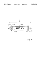
- FIG. 4 is a view of the home station without the tees or line.
- FIG. 5 illustrates three optional features--an awl, a rack for ball spotters, and a ball repair fork.
- FIG. 6 is a section of a preferred version of our tee showing the connection of the line through the side.
- the home station 1 is seen to have temporarily fixed to it tees 2 and 3 tethered together by line 4 which is inserted and tied through a bore 5 in probe 6 of tee 2 and bore 11 in tee stem 7 of tee 3.
- tee 3 is longer than tee 2, having a stem 7 between cylindrical shoulder 8 and probe 9, while probe 6 of the shorter tee 2 attaches integrally directly to upper section 10.
- Home station 1 has two end flanges 12 and a central body portion 13, which may be cylindrical as shown in FIG. 1 or flat as seen in FIG. 5. Tees 2 and 3 are attached to home station 1 by pegs 17 inserted into them, as will be seen in FIGS. 2, 3, and 4.
- Line 4 is preferably a monofilament such as a nylon fishing line.
- the invention is described and illustrated showing the longer tee 3 being used as the working tee--that is, the tee which will support the ball. This will normally be the case when the user intends to use a driver or other wood club, or a low numbered iron, to strike the ball, while the shorter tee 2 will normally be used when a higher numbered iron is to be used to strike the ball held at a lower height; however, either tee may be used for either purpose within the concept of our invention.
- FIG. 2a tee 3 is seen to have been removed from the home station 1 (see FIG. 1) and the user 14 is pushing it into the ground 15 while holding ball 16. Tee 3 is still connected by line 4 to tee 2, which is lying on ground 15.
- FIG. 2b shows that tee 3 was removed from peg 17 on home station 1; home station 1 may be used as an aid to pushing the shorter tee 2 into the ground 15 while line 4 remains in place to prevent tee 3 from being knocked or otherwise moved farther from the area than the length of line 4 will permit.
- Home station 1 may be left in place on tee 2 while the ball 16 is struck from tee 3.
- the tees 2 and 3 are made preferably of high density polyethylene (HDPE) and may be either injection molded or machined from extruded HDPE rod. Other synthetic resins of similar hardness, toughness or resiliency may be used. Tee 2 may be replaced by a tee similar to tee 3--that is, with a longer tee if desired. Home station 1 may also be used as an aid to insertion of tee 3 into the ground 15, in the same manner as illustrated for tee 2.
- HDPE high density polyethylene
- Other synthetic resins of similar hardness, toughness or resiliency may be used.
- Tee 2 may be replaced by a tee similar to tee 3--that is, with a longer tee if desired.
- Home station 1 may also be used as an aid to insertion of tee 3 into the ground 15, in the same manner as illustrated for tee 2.
- Tees 2 and 3 each have a central socket 23 designed to receive complementarily shaped pegs 17 on home station 1 (see FIG. 2b).
- the top surfaces 21 of tees 2 and 3 are slightly concave and are of a diameter slightly less than shoulder 8 of tee 3 or upper section 10 of tee 2, defining a shelf 22 around the perimeter of the tee.
- a bore (bores 5 and 11 in FIG. 1) on each tee comprises a large diameter portion 24a and a small diameter portion 24b.
- Line 4 is held in place by a knot 26 which will pass through large diameter portion 24a but not small diameter portion 24b.
- Below stem 7 of tee 3 is a conical point 25; the overall angle of the point 25 is preferably about 25°, but may vary from about 12 degrees to about 30 degrees.
- Tee 2 may have a similar conical point 27.
- top surface 21 may be the top surface of shoulder 8 and/or upper section 10--see FIG. 6.
- Line 4 should be at least about six inches long but need not be more than about six feet. We prefer to use a line 4 of from one to five feet long.
- a rack having sockets for the pointed ends of the tees; in this case the sockets in the tees may be dispensed with and the rack may have a rounded protrusion for contacting the top of the tee to push it into the ground.
- FIG. 4 illustrates a version of the home station 1 in which the body portion 27 is flat and may contain a logo or advertising message 28.
- Flanges 12 and pegs 17 are similar to those of FIGS. 1 and 2. Persons skilled in the art will realize that body portion 27 and flanges 12 may be merged in a monolithic body portion which may be cylindrical or otherwise variously shaped.
- FIG. 5 shows our invention with three optional accessories--an awl 29, a ball spotter rack 30 holding ball spotters 31, and a ball mark repair fork 34.
- Ball spotters 31 are detachable and may be held in place by awl 29 when it is in the storage position shown by the dotted lines; awl 29 and ball mark repair fork 34 may pivot on pivot 33, awl 29 may be used in piloting a hole in hard ground for a tee, and ball mark repair fork 34 is used for repairing marks on balls.
- FIG. 6 the preferred variation of the tee 3 is shown in section, revealing the socket 23 and a single bore 32 for the monofilament line 4 having knot 26 which prevents the line 4 from passing through the bore 32.
- a similar single bore may be used in the shorter tee 2.
- the bore 32 will be placed at a level in socket 23 below the farthest point which can be reached by a peg 17, although this is not considered essential.
- our invention comprises two tees tethered together by a line or cord, and further comprises two tees tethered together by a line or cord, the tees having means for mooring to a home station designed as a handle to aid in inserting the tees into the ground.
Abstract
Two golf tees are tethered together by a cord, preferably a monofilament which passes through the stems of the tees. Pegs mounted on a home station are inserted into the tees for storage and carrying the tees through the game. In use, both tees are inserted into the ground, and the tether prevents loss of the tees. The tees are made of high density polyethylene or other similar tough material, as the assembly is designed to prevent loss and breakage of tees.
Description
This invention relates to golf tees and particularly to a novel pair of tees held loosely together by a relatively long cord. The tees are preferably temporarily moored to a home station having pegs inserted into sockets in the ball-supporting ends of the tees. The home station may be shaped and used like a handle for aid in inserting the tees into the ground.
Even occasional golfers are familiar with the sight of broken and lost tees littering the grounds, particularly around the driving areas. Golfers often carry an excess of tees to be sure of having good ones throughout the course; this means frequently purchasing packets of tees and keeping track of them throughout the game. Sometimes the tees are broken not on being struck by a club, but in the process of pushing into hard ground. Inevitably, many golfers do not remove the remains of such broken tees.
Those who maintain golf courses must provide the attention and labor necessary to remove the broken and lost tees, and it is not uncommon for the well-used and precisely set lawnmowers on golf courses to be damaged by stray golf tees. The common "expendable" wooden tee is a nuisance and an expense for golf course caretakers and users alike.
Wampler, in U.S. Design Pat. No. 279,121 illustrates a sturdily constructed tee which is tethered to a permanent base, suggesting use in driving ranges. Wampler does not address the needs of the golfer playing an entire golf course, nor the caretakers of such a course who cannot construct permanent tees such as may be used on a driving range. The art is in need of a tee which is portable, resistant to destruction, and always readily found after use.
Our invention provides golf tees which are virtually unbreakable and unlosable. At the same time, they are in a convenient form which can be easily carried and inserted into the ground.
Two tees, made of a hard and/or dense synthetic resin, are tethered together by a strong thin cord. The golfer inserts one of the tees in the ground for use in driving or otherwise striking the ball, and the other is anchored in the ground nearby. When the tee supporting the ball is struck and removed by the golf club, it is held by the tether to the anchored tee and accordingly is not lost. Being made of a strong synthetic plastic, the tee does not break and may be used many times. Of course, either tee may be used for either purpose, supporting the ball or anchoring. The two tees may be of different lengths so the longer may conveniently be used for woods and the shorter one for irons.
Our invention includes a handle or home station for the tee couple, which includes two pegs or protrusions designed to be inserted into complementary sockets or holes, preferably with a snug fit, in the tops of the tees. The assembly, comprising the home station, the two tees, and the tether, which may be wound around the home station, is easily placed in a shirt pocket or golf bag pocket for ready retrieval at the next point of use. The home station is preferably shaped to act as a handle to assist in the insertion of a tee into the ground. Accessories may be built into or on the home station; such accessories include an awl, for aid in making a hole in hard ground for the tee, an attachment or slot for carrying ball markers, and/or a ball repair fork.
FIG. 1 is a side view of the coupled tees moored to the home station.
FIGS. 2a and 2b illustrate the insertion of the coupled tees into the ground in preparation for use.
FIG. 3 illustrates the detail of the tether connections and the socket in the tees for insertion of the complementary peg on the home station.
FIG. 4 is a view of the home station without the tees or line.
FIG. 5 illustrates three optional features--an awl, a rack for ball spotters, and a ball repair fork.
FIG. 6 is a section of a preferred version of our tee showing the connection of the line through the side.
In FIG. 1, the home station 1 is seen to have temporarily fixed to it tees 2 and 3 tethered together by line 4 which is inserted and tied through a bore 5 in probe 6 of tee 2 and bore 11 in tee stem 7 of tee 3. In this version of the invention, tee 3 is longer than tee 2, having a stem 7 between cylindrical shoulder 8 and probe 9, while probe 6 of the shorter tee 2 attaches integrally directly to upper section 10. Home station 1 has two end flanges 12 and a central body portion 13, which may be cylindrical as shown in FIG. 1 or flat as seen in FIG. 5. Tees 2 and 3 are attached to home station 1 by pegs 17 inserted into them, as will be seen in FIGS. 2, 3, and 4. Line 4 is preferably a monofilament such as a nylon fishing line.
The invention is described and illustrated showing the longer tee 3 being used as the working tee--that is, the tee which will support the ball. This will normally be the case when the user intends to use a driver or other wood club, or a low numbered iron, to strike the ball, while the shorter tee 2 will normally be used when a higher numbered iron is to be used to strike the ball held at a lower height; however, either tee may be used for either purpose within the concept of our invention.
In FIG. 2a, tee 3 is seen to have been removed from the home station 1 (see FIG. 1) and the user 14 is pushing it into the ground 15 while holding ball 16. Tee 3 is still connected by line 4 to tee 2, which is lying on ground 15. FIG. 2b shows that tee 3 was removed from peg 17 on home station 1; home station 1 may be used as an aid to pushing the shorter tee 2 into the ground 15 while line 4 remains in place to prevent tee 3 from being knocked or otherwise moved farther from the area than the length of line 4 will permit. Home station 1 may be left in place on tee 2 while the ball 16 is struck from tee 3. The tees 2 and 3 are made preferably of high density polyethylene (HDPE) and may be either injection molded or machined from extruded HDPE rod. Other synthetic resins of similar hardness, toughness or resiliency may be used. Tee 2 may be replaced by a tee similar to tee 3--that is, with a longer tee if desired. Home station 1 may also be used as an aid to insertion of tee 3 into the ground 15, in the same manner as illustrated for tee 2.
The details of the preferred form of tee are shown in FIG. 3. Tees 2 and 3 each have a central socket 23 designed to receive complementarily shaped pegs 17 on home station 1 (see FIG. 2b). In the preferred form of our tee, the top surfaces 21 of tees 2 and 3 are slightly concave and are of a diameter slightly less than shoulder 8 of tee 3 or upper section 10 of tee 2, defining a shelf 22 around the perimeter of the tee. A bore ( bores 5 and 11 in FIG. 1) on each tee comprises a large diameter portion 24a and a small diameter portion 24b. Line 4 is held in place by a knot 26 which will pass through large diameter portion 24a but not small diameter portion 24b. Below stem 7 of tee 3 is a conical point 25; the overall angle of the point 25 is preferably about 25°, but may vary from about 12 degrees to about 30 degrees. Tee 2 may have a similar conical point 27.
FIG. 4 illustrates a version of the home station 1 in which the body portion 27 is flat and may contain a logo or advertising message 28. Flanges 12 and pegs 17 are similar to those of FIGS. 1 and 2. Persons skilled in the art will realize that body portion 27 and flanges 12 may be merged in a monolithic body portion which may be cylindrical or otherwise variously shaped.
FIG. 5 shows our invention with three optional accessories--an awl 29, a ball spotter rack 30 holding ball spotters 31, and a ball mark repair fork 34. Ball spotters 31 are detachable and may be held in place by awl 29 when it is in the storage position shown by the dotted lines; awl 29 and ball mark repair fork 34 may pivot on pivot 33, awl 29 may be used in piloting a hole in hard ground for a tee, and ball mark repair fork 34 is used for repairing marks on balls.
In FIG. 6, the preferred variation of the tee 3 is shown in section, revealing the socket 23 and a single bore 32 for the monofilament line 4 having knot 26 which prevents the line 4 from passing through the bore 32. A similar single bore may be used in the shorter tee 2. Preferably the bore 32 will be placed at a level in socket 23 below the farthest point which can be reached by a peg 17, although this is not considered essential.
Thus it is seen that our invention comprises two tees tethered together by a line or cord, and further comprises two tees tethered together by a line or cord, the tees having means for mooring to a home station designed as a handle to aid in inserting the tees into the ground. The invention is otherwise described in the claims below.
Claims (12)
1. A golfing device comprising (a) two golf tees, each of said golf tees having a top surface and a pointed end, each golf tee also having a socket in the center of its top surface, (b) a cord connecting said golf tees, and (c) a home station, said home station comprising a body portion and two pegs, each of said pegs being of a shape and size to fit in a socket of one of said tees.
2. A golfing device of claim 1 wherein said cord connects said golf tees from a transverse bore in each of said golf tees.
3. A golfing device of claim 2 wherein said transverse bore includes a portion of relatively large internal diameter and a portion of relatively small internal diameter.
4. A golfing device of claim 2 wherein said transverse bore is from an outside surface to said socket.
5. A golfing device of claim 1 wherein said home station includes two end flanges.
6. A golfing device of claim 1 wherein said pointed end is conical and has a point angle of about 12 to about 30 degrees.
7. A golfing device of claim 1 wherein said home station includes a rack of ball spotters detachably mounted thereon.
8. A golfing device of claim 1 wherein said body portion of said home station is substantially cylindrical.
9. A golfing device of claim 1 wherein said top surfaces of said golf tees are slightly concave.
10. A golfing device of claim 1 wherein said body portion of said home station is substantially flat.
11. A golfing device of claim 1 wherein said home station includes at least one of an awl and a ball repair fork mounted thereon.
12. A golfing device comprising (a) two golf tees, (b) a cord connecting said golf tees, and (c) means for storing and carrying said golf tees and cord, said means for storing and carrying including means complementarily fitting said tees.
Priority Applications (1)
| Application Number | Priority Date | Filing Date | Title |
|---|---|---|---|
| US08/929,689 US5820490A (en) | 1997-09-15 | 1997-09-15 | Coupled golf tees |
Applications Claiming Priority (1)
| Application Number | Priority Date | Filing Date | Title |
|---|---|---|---|
| US08/929,689 US5820490A (en) | 1997-09-15 | 1997-09-15 | Coupled golf tees |
Publications (1)
| Publication Number | Publication Date |
|---|---|
| US5820490A true US5820490A (en) | 1998-10-13 |
Family
ID=25458285
Family Applications (1)
| Application Number | Title | Priority Date | Filing Date |
|---|---|---|---|
| US08/929,689 Expired - Fee Related US5820490A (en) | 1997-09-15 | 1997-09-15 | Coupled golf tees |
Country Status (1)
| Country | Link |
|---|---|
| US (1) | US5820490A (en) |
Cited By (13)
| Publication number | Priority date | Publication date | Assignee | Title |
|---|---|---|---|---|
| GB2397534A (en) * | 2003-01-27 | 2004-07-28 | Kevin Dodd | Golf tee anchor |
| US20070219022A1 (en) * | 2006-03-15 | 2007-09-20 | Moldetk Precision Corp. | Combined golf tee |
| US20080009372A1 (en) * | 2006-07-05 | 2008-01-10 | Moldetk Precision Corp. | Golf tee |
| US20080064532A1 (en) * | 2006-07-05 | 2008-03-13 | Moldetk Precision Corp. | Golf tee |
| US7691011B1 (en) * | 2007-08-16 | 2010-04-06 | Roman Gregory S | Durable golf tee |
| US20140155196A1 (en) * | 2012-11-26 | 2014-06-05 | Lon Klein | Golf tee insertion tool |
| US20140162810A1 (en) * | 2012-12-06 | 2014-06-12 | Hyung Jae PARK | Golf tee set |
| USD740627S1 (en) * | 2013-06-14 | 2015-10-13 | Wayne Paul Johnson | Socket and wrench tether connection cable and collet |
| US20170304696A1 (en) * | 2016-04-24 | 2017-10-26 | Jefferey Frederick Brandenburg | BioPeg TetherTee |
| US10124223B1 (en) | 2016-12-17 | 2018-11-13 | Robert N. Porter | Low-interference golf tee saver set |
| US10363467B2 (en) * | 2016-04-24 | 2019-07-30 | Jefferey Frederick Brandenburg | Tetherable golf tee and teeing system |
| US20220339508A1 (en) * | 2021-03-31 | 2022-10-27 | Andrew R. Spriegel | Rigid Golf Ball Tee |
| US11617930B1 (en) * | 2021-12-07 | 2023-04-04 | Bruce Johnson | Golf tee tether assembly |
Citations (12)
| Publication number | Priority date | Publication date | Assignee | Title |
|---|---|---|---|---|
| US1631270A (en) * | 1926-07-31 | 1927-06-07 | Eleanor H Jones | Golf tee |
| US1655751A (en) * | 1927-05-28 | 1928-01-10 | Earl F Cody | Golf-ball tee |
| US1730046A (en) * | 1926-06-21 | 1929-10-01 | William C Stow | Writing implement |
| US1736583A (en) * | 1928-03-02 | 1929-11-19 | Ulric C Deike | Golf tee |
| US2668710A (en) * | 1949-09-14 | 1954-02-09 | Richard F Carlson | Golf tee |
| US3194557A (en) * | 1962-12-27 | 1965-07-13 | John M Holley | Ball practicing device |
| US3220727A (en) * | 1963-03-15 | 1965-11-30 | Walter V Legan | Device for inserting golf tees into the ground |
| US4893818A (en) * | 1988-08-03 | 1990-01-16 | Patrick Liccardello | Golf tee |
| US4998732A (en) * | 1989-11-15 | 1991-03-12 | Gallant Thomas M | Golf tee |
| US5211395A (en) * | 1991-09-25 | 1993-05-18 | Liao Henry H | Golf tool |
| US5221090A (en) * | 1992-04-28 | 1993-06-22 | Hong Bum K | Golf tee |
| US5242170A (en) * | 1992-05-14 | 1993-09-07 | Super Tee, Inc. | Golf tee |
-
1997
- 1997-09-15 US US08/929,689 patent/US5820490A/en not_active Expired - Fee Related
Patent Citations (12)
| Publication number | Priority date | Publication date | Assignee | Title |
|---|---|---|---|---|
| US1730046A (en) * | 1926-06-21 | 1929-10-01 | William C Stow | Writing implement |
| US1631270A (en) * | 1926-07-31 | 1927-06-07 | Eleanor H Jones | Golf tee |
| US1655751A (en) * | 1927-05-28 | 1928-01-10 | Earl F Cody | Golf-ball tee |
| US1736583A (en) * | 1928-03-02 | 1929-11-19 | Ulric C Deike | Golf tee |
| US2668710A (en) * | 1949-09-14 | 1954-02-09 | Richard F Carlson | Golf tee |
| US3194557A (en) * | 1962-12-27 | 1965-07-13 | John M Holley | Ball practicing device |
| US3220727A (en) * | 1963-03-15 | 1965-11-30 | Walter V Legan | Device for inserting golf tees into the ground |
| US4893818A (en) * | 1988-08-03 | 1990-01-16 | Patrick Liccardello | Golf tee |
| US4998732A (en) * | 1989-11-15 | 1991-03-12 | Gallant Thomas M | Golf tee |
| US5211395A (en) * | 1991-09-25 | 1993-05-18 | Liao Henry H | Golf tool |
| US5221090A (en) * | 1992-04-28 | 1993-06-22 | Hong Bum K | Golf tee |
| US5242170A (en) * | 1992-05-14 | 1993-09-07 | Super Tee, Inc. | Golf tee |
Cited By (15)
| Publication number | Priority date | Publication date | Assignee | Title |
|---|---|---|---|---|
| GB2397534A (en) * | 2003-01-27 | 2004-07-28 | Kevin Dodd | Golf tee anchor |
| US20070219022A1 (en) * | 2006-03-15 | 2007-09-20 | Moldetk Precision Corp. | Combined golf tee |
| US20080009372A1 (en) * | 2006-07-05 | 2008-01-10 | Moldetk Precision Corp. | Golf tee |
| US20080064532A1 (en) * | 2006-07-05 | 2008-03-13 | Moldetk Precision Corp. | Golf tee |
| US7645202B2 (en) * | 2006-07-05 | 2010-01-12 | Moldetk Precision Corp. | Golf tee |
| US7691011B1 (en) * | 2007-08-16 | 2010-04-06 | Roman Gregory S | Durable golf tee |
| US20140155196A1 (en) * | 2012-11-26 | 2014-06-05 | Lon Klein | Golf tee insertion tool |
| US9174105B2 (en) * | 2012-11-26 | 2015-11-03 | Lon Klein | Golf tee insertion tool |
| US20140162810A1 (en) * | 2012-12-06 | 2014-06-12 | Hyung Jae PARK | Golf tee set |
| USD740627S1 (en) * | 2013-06-14 | 2015-10-13 | Wayne Paul Johnson | Socket and wrench tether connection cable and collet |
| US20170304696A1 (en) * | 2016-04-24 | 2017-10-26 | Jefferey Frederick Brandenburg | BioPeg TetherTee |
| US10363467B2 (en) * | 2016-04-24 | 2019-07-30 | Jefferey Frederick Brandenburg | Tetherable golf tee and teeing system |
| US10124223B1 (en) | 2016-12-17 | 2018-11-13 | Robert N. Porter | Low-interference golf tee saver set |
| US20220339508A1 (en) * | 2021-03-31 | 2022-10-27 | Andrew R. Spriegel | Rigid Golf Ball Tee |
| US11617930B1 (en) * | 2021-12-07 | 2023-04-04 | Bruce Johnson | Golf tee tether assembly |
Similar Documents
| Publication | Publication Date | Title |
|---|---|---|
| US6878071B1 (en) | Golf club with ball retrieval and tee placement | |
| US5820490A (en) | Coupled golf tees | |
| US5743819A (en) | Golf tee setter | |
| US6290617B1 (en) | Golf divot replacement tool | |
| US6679793B2 (en) | Golf tee structure | |
| US7645202B2 (en) | Golf tee | |
| US6216587B1 (en) | Golf ball marking device | |
| US20060100037A1 (en) | Golf tees and accessories | |
| US5766086A (en) | Golf game | |
| US20120115629A1 (en) | Divot Caddy | |
| US5830076A (en) | Golf practice target apparatus | |
| US20090082127A1 (en) | Cigar holder and divot repair tool | |
| US6200226B1 (en) | Golf putter | |
| US6482111B1 (en) | Golf tee for driving ranges | |
| US6309316B1 (en) | Football tee with onside kick ball support | |
| US7344456B2 (en) | Flexible golf tee | |
| US20060223655A1 (en) | Durable golf tee | |
| US20210197055A1 (en) | Batting Tee | |
| US8382615B2 (en) | Golf turf repair device | |
| US20070093321A1 (en) | Golf tee leveling device | |
| US5775538A (en) | Golf tee shaker | |
| US20060205537A1 (en) | Device for supporting a golf ball | |
| US20080287219A1 (en) | Golf tee support apparatus | |
| KR20020034840A (en) | Golf tee | |
| US11794083B1 (en) | Portable magnetic multifunction golf accessory |
Legal Events
| Date | Code | Title | Description |
|---|---|---|---|
| REMI | Maintenance fee reminder mailed | ||
| LAPS | Lapse for failure to pay maintenance fees | ||
| STCH | Information on status: patent discontinuation |
Free format text: PATENT EXPIRED DUE TO NONPAYMENT OF MAINTENANCE FEES UNDER 37 CFR 1.362 |
|
| FP | Lapsed due to failure to pay maintenance fee |
Effective date: 20021013 |