US5815273A - Device to determine the shape of pane-shaped objects - Google Patents
Device to determine the shape of pane-shaped objects Download PDFInfo
- Publication number
- US5815273A US5815273A US08/736,013 US73601396A US5815273A US 5815273 A US5815273 A US 5815273A US 73601396 A US73601396 A US 73601396A US 5815273 A US5815273 A US 5815273A
- Authority
- US
- United States
- Prior art keywords
- pane
- optical sensors
- row
- sensors
- parallel
- Prior art date
- Legal status (The legal status is an assumption and is not a legal conclusion. Google has not performed a legal analysis and makes no representation as to the accuracy of the status listed.)
- Expired - Fee Related
Links
- 230000003287 optical effect Effects 0.000 claims abstract description 38
- 230000004888 barrier function Effects 0.000 claims abstract description 13
- 230000007704 transition Effects 0.000 abstract description 3
- 239000011521 glass Substances 0.000 description 8
- 238000005259 measurement Methods 0.000 description 5
- 238000007789 sealing Methods 0.000 description 2
- 238000004519 manufacturing process Methods 0.000 description 1
- 238000000034 method Methods 0.000 description 1
- 230000001960 triggered effect Effects 0.000 description 1
Images
Classifications
-
- E—FIXED CONSTRUCTIONS
- E06—DOORS, WINDOWS, SHUTTERS, OR ROLLER BLINDS IN GENERAL; LADDERS
- E06B—FIXED OR MOVABLE CLOSURES FOR OPENINGS IN BUILDINGS, VEHICLES, FENCES OR LIKE ENCLOSURES IN GENERAL, e.g. DOORS, WINDOWS, BLINDS, GATES
- E06B3/00—Window sashes, door leaves, or like elements for closing wall or like openings; Layout of fixed or moving closures, e.g. windows in wall or like openings; Features of rigidly-mounted outer frames relating to the mounting of wing frames
- E06B3/66—Units comprising two or more parallel glass or like panes permanently secured together
- E06B3/673—Assembling the units
- E06B3/67365—Transporting or handling panes, spacer frames or units during assembly
-
- G—PHYSICS
- G01—MEASURING; TESTING
- G01B—MEASURING LENGTH, THICKNESS OR SIMILAR LINEAR DIMENSIONS; MEASURING ANGLES; MEASURING AREAS; MEASURING IRREGULARITIES OF SURFACES OR CONTOURS
- G01B11/00—Measuring arrangements characterised by the use of optical techniques
- G01B11/24—Measuring arrangements characterised by the use of optical techniques for measuring contours or curvatures
- G01B11/245—Measuring arrangements characterised by the use of optical techniques for measuring contours or curvatures using a plurality of fixed, simultaneously operating transducers
-
- G—PHYSICS
- G05—CONTROLLING; REGULATING
- G05B—CONTROL OR REGULATING SYSTEMS IN GENERAL; FUNCTIONAL ELEMENTS OF SUCH SYSTEMS; MONITORING OR TESTING ARRANGEMENTS FOR SUCH SYSTEMS OR ELEMENTS
- G05B19/00—Programme-control systems
- G05B19/02—Programme-control systems electric
- G05B19/42—Recording and playback systems, i.e. in which the programme is recorded from a cycle of operations, e.g. the cycle of operations being manually controlled, after which this record is played back on the same machine
- G05B19/4202—Recording and playback systems, i.e. in which the programme is recorded from a cycle of operations, e.g. the cycle of operations being manually controlled, after which this record is played back on the same machine preparation of the programme medium using a drawing, a model
- G05B19/4205—Recording and playback systems, i.e. in which the programme is recorded from a cycle of operations, e.g. the cycle of operations being manually controlled, after which this record is played back on the same machine preparation of the programme medium using a drawing, a model in which a drawing is traced or scanned and corresponding data recorded
-
- E—FIXED CONSTRUCTIONS
- E06—DOORS, WINDOWS, SHUTTERS, OR ROLLER BLINDS IN GENERAL; LADDERS
- E06B—FIXED OR MOVABLE CLOSURES FOR OPENINGS IN BUILDINGS, VEHICLES, FENCES OR LIKE ENCLOSURES IN GENERAL, e.g. DOORS, WINDOWS, BLINDS, GATES
- E06B3/00—Window sashes, door leaves, or like elements for closing wall or like openings; Layout of fixed or moving closures, e.g. windows in wall or like openings; Features of rigidly-mounted outer frames relating to the mounting of wing frames
- E06B3/66—Units comprising two or more parallel glass or like panes permanently secured together
- E06B3/673—Assembling the units
- E06B2003/67395—Non-planar units or of curvilinear outline, e.g. for vehicles
-
- G—PHYSICS
- G05—CONTROLLING; REGULATING
- G05B—CONTROL OR REGULATING SYSTEMS IN GENERAL; FUNCTIONAL ELEMENTS OF SUCH SYSTEMS; MONITORING OR TESTING ARRANGEMENTS FOR SUCH SYSTEMS OR ELEMENTS
- G05B2219/00—Program-control systems
- G05B2219/30—Nc systems
- G05B2219/37—Measurements
- G05B2219/37061—Use matrix of optical sensors to detect form, edges of object
Definitions
- the invention relates to a device for determining the shape of pane-shaped objects, particularly thermal window panes.
- This type of device can be integrated into a device of practically any design with which pane-shaped objects, particularly thermal window panes, are transported.
- the device can be a conveyor device by which thermal window panes are transported to a sealing device.
- the shape of the contour needs to be determined precisely so that the devices for subsequent processing procedures, for example a device for sealing the edge joints of thermal window panes, can be controlled accordingly.
- a device that makes this possible is known from, for instance, DE-40-33 585 A.
- the object of the present invention is to indicate a device of the type mentioned above that operates quickly and reliably and is inexpensive to produce.
- This object is achieved according to the invention by providing multiple optical sensors that are arranged in at least one row and by orienting this row parallel to the plane of the pane-shaped object, as well as at an angle to the direction of travel.
- the Y coordinates, i.e., the coordinates normal to the direction of travel X, of the edge points of a pane-shaped object such as a thermal window pane can be simply and continuously determined by having the optical sensors, which are arranged in one row at an angle to the direction of travel, determine the point up to which the window pane extends in the Y direction.
- the corresponding X coordinates of the edge points are determined by, for example, a motion pickup that is associated with the conveyor device so that the entire external contour of the pane-shaped object, for instance a thermal window pane, can be determined in a single pass in which the pane-shaped object is moved past the row of optical sensors.
- the FIGURE illustrates an embodiment of the invention.
- a device that consists essentially of a support device 2 and a conveyor device, for example a conveyor belt 4 or a row of transport rollers.
- Support device 2 is, as is basically known, a support wall, which is tilted 5 degrees to 8 degrees to the rear and which the pane-shaped object, for example any window pane 1, especially a thermal window pane, abuts.
- Conveyor belts or transport rollers, which may also be motor-driven, can be integrated into the support wall.
- Air-cushion walls may also be used as a support device.
- support device 2 is a horizontal (air cushion-) table on which the window pane 1 lies horizontally and is moved by transport rollers or conveyor belts in the direction of arrow X.
- window pane 1 stands with its bottom edge on conveyor belt 4, which runs over deflection rollers 5, 6 and is driven by, for example, deflection roller 6.
- a motion pickup 20, which is used in one embodiment to determine the X coordinates of edge points 9, 11, 12 of the window pane, is connected to conveyor belt 4, a deflection roller 5, 6, or the drive of conveyor belt 4.
- support device 2 are optical sensors 7 which are used to determine the Y coordinates of edge points 9, 11, 12 of window pane 1.
- Said sensors 7, which are, for example, reflected-light barriers, are arranged in one row 3, which is oriented parallel to the plane of movement of window pane 1 and at right angles to direction of travel X.
- the X and Y coordinates of edge point 9 of window pane 1 can be determined with the device according to the invention as follows.
- the light rays of the reflected-light barriers of all sensors 7 which are arranged between bottom end 13 of row 3 and edge point 9 of window pane 1 are reflected. Those sensors 7 which lie above edge point 9 are not activated since the light rays of their reflected-light barriers are not reflected.
- the Y coordinate of edge point 9 is determined from the transition from reflection to non-reflection (highest reflected light barrier/lowest non-reflected reflected-light barrier).
- the corresponding X coordinate of edge point 9 is determined, for example, in that as glass pane 1 advances, the measurement of the X coordinate by motion pickup 20 is triggered by the light of the reflected-light barriers of sensors 7 in row 3 being reflected by the leading edge of glass pane 1 and the X coordinate up to edge point 9 then being determined by the feed path being measured by motion pickup 20. Measurement data may be analyzed and stored in an analysis and storage unit 22 and subsequently processed in a processing device 24.
- a second row 10 of optical sensors 7, for instance reflected-light barriers is provided which is oriented in direction of travel X.
- the X-coordinate of edge point 9 can also be determined by determining the distance in the X direction between edge point 9 in row 3 of sensors 7 and edge point 11 and/or 12, which triggers a constantly changing measurement signal in row 10 of sensors 7 as glass pane 1 is moved in the X direction.
- row 3 of sensors 7 can be oriented at an angle of greater or less than 90 degrees to direction of travel X.
- a motion pickup which is associated with conveyor belt 4 can also be combined with a row 10 of sensors 7, which is oriented parallel to the direction of travel.
- glass pane 1 remains stationary and a beam in which row 3 of optical sensors 7 is arranged is moved past the glass pane.
- sensors 7 are arranged so that they are spread over supporting device 2, for example the air-cushion wall.
- sensors 7 are arranged in multiple parallel rows 3 and/or 10, equidistant from each other in each row 3 and/or 10.
- Optical sensors 7 can also be arranged in row 3 (vertically to direction of travel X) and/or in row 10 (parallel to travel direction X) in two rows located right next to one another where sensors 7 of one row are arranged with a gap between sensors 7 and the neighboring row. Thus the distance between sensors 7 of one row and the next, which is necessitated by the manufacturing process, is reduced.
- a device for determining the shape of pane-shaped objects has a support device which the pane-shaped object abuts, optical sensors, a conveyance device to move the pane-shaped object and the optical sensors relative to each other, and a device for determining the feed path.
- the optical sensors arranged in one row are preferably reflected-light barriers. Light rays are reflected in the area of the object (up to its edge) but not past to it, so that the Y coordinate of the point is determined from the transition from reflection to non-reflection at the reflected-light barrier.
Landscapes
- Engineering & Computer Science (AREA)
- Physics & Mathematics (AREA)
- General Physics & Mathematics (AREA)
- Civil Engineering (AREA)
- Structural Engineering (AREA)
- Automation & Control Theory (AREA)
- Length Measuring Devices By Optical Means (AREA)
- Length Measuring Devices With Unspecified Measuring Means (AREA)
- Control Of Conveyors (AREA)
- Image Processing (AREA)
Abstract
A device for determining the shape of pane-shaped objects (1), particularly thermal window panes, has a support device which a pane-shaped object (1) abuts, optical sensors (7), a conveyor device (4, 5, 6) to move a pane-shaped object (1) and optical sensors (7) relative to one another, and a device for determining the travel path. There are multiple optical sensors (7) which are arranged in at least one row (3), where this row (3) is oriented parallel to the plane of pane-shaped object (1), as well as at an angle to the direction of travel (X). Optical sensors (7) which are arranged in one row (3) are reflected-light barriers. Light rays are reflected in the area of an object (1) (up to the edge of the object (9)) but not past to it, so that the Y-coordinate of a point on the object (9) is determined by the transition from reflection to non-reflection at sensor (7).
Description
The invention relates to a device for determining the shape of pane-shaped objects, particularly thermal window panes.
This type of device can be integrated into a device of practically any design with which pane-shaped objects, particularly thermal window panes, are transported. For instance, the device can be a conveyor device by which thermal window panes are transported to a sealing device.
Particularly in the case of objects that are not rectangular or square, and especially thermal window panes, the shape of the contour needs to be determined precisely so that the devices for subsequent processing procedures, for example a device for sealing the edge joints of thermal window panes, can be controlled accordingly. A device that makes this possible is known from, for instance, DE-40-33 585 A.
However, the device described in DE 40 33 585 A has the disadvantage that two line cameras must be provided when the dimensions of the objects are large in order to capture the contour and that the line cameras are sensitive to disruptive external light influences. In addition, good line cameras are expensive.
The object of the present invention is to indicate a device of the type mentioned above that operates quickly and reliably and is inexpensive to produce.
This object is achieved according to the invention by providing multiple optical sensors that are arranged in at least one row and by orienting this row parallel to the plane of the pane-shaped object, as well as at an angle to the direction of travel.
With the present invention, the Y coordinates, i.e., the coordinates normal to the direction of travel X, of the edge points of a pane-shaped object such as a thermal window pane can be simply and continuously determined by having the optical sensors, which are arranged in one row at an angle to the direction of travel, determine the point up to which the window pane extends in the Y direction. The corresponding X coordinates of the edge points are determined by, for example, a motion pickup that is associated with the conveyor device so that the entire external contour of the pane-shaped object, for instance a thermal window pane, can be determined in a single pass in which the pane-shaped object is moved past the row of optical sensors.
Additional characteristics and advantages of the invention will be apparent from the following description of embodiments of the invention with reference to the drawing.
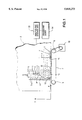
The FIGURE illustrates an embodiment of the invention.
In the drawing a device according to the invention is schematically shown that consists essentially of a support device 2 and a conveyor device, for example a conveyor belt 4 or a row of transport rollers. Support device 2 is, as is basically known, a support wall, which is tilted 5 degrees to 8 degrees to the rear and which the pane-shaped object, for example any window pane 1, especially a thermal window pane, abuts. Conveyor belts or transport rollers, which may also be motor-driven, can be integrated into the support wall. Air-cushion walls may also be used as a support device.
In another embodiment support device 2 is a horizontal (air cushion-) table on which the window pane 1 lies horizontally and is moved by transport rollers or conveyor belts in the direction of arrow X.
In the embodiment shown in the drawing, window pane 1 stands with its bottom edge on conveyor belt 4, which runs over deflection rollers 5, 6 and is driven by, for example, deflection roller 6. A motion pickup 20, which is used in one embodiment to determine the X coordinates of edge points 9, 11, 12 of the window pane, is connected to conveyor belt 4, a deflection roller 5, 6, or the drive of conveyor belt 4. In support device 2 are optical sensors 7 which are used to determine the Y coordinates of edge points 9, 11, 12 of window pane 1. Said sensors 7, which are, for example, reflected-light barriers, are arranged in one row 3, which is oriented parallel to the plane of movement of window pane 1 and at right angles to direction of travel X.
The X and Y coordinates of edge point 9 of window pane 1 can be determined with the device according to the invention as follows. The light rays of the reflected-light barriers of all sensors 7 which are arranged between bottom end 13 of row 3 and edge point 9 of window pane 1 are reflected. Those sensors 7 which lie above edge point 9 are not activated since the light rays of their reflected-light barriers are not reflected. The Y coordinate of edge point 9 is determined from the transition from reflection to non-reflection (highest reflected light barrier/lowest non-reflected reflected-light barrier). The corresponding X coordinate of edge point 9 is determined, for example, in that as glass pane 1 advances, the measurement of the X coordinate by motion pickup 20 is triggered by the light of the reflected-light barriers of sensors 7 in row 3 being reflected by the leading edge of glass pane 1 and the X coordinate up to edge point 9 then being determined by the feed path being measured by motion pickup 20. Measurement data may be analyzed and stored in an analysis and storage unit 22 and subsequently processed in a processing device 24.
Alternatively, instead of motion pickup 20, which is associated with conveyor belt 4, a second row 10 of optical sensors 7, for instance reflected-light barriers, is provided which is oriented in direction of travel X. In this case the X-coordinate of edge point 9 can also be determined by determining the distance in the X direction between edge point 9 in row 3 of sensors 7 and edge point 11 and/or 12, which triggers a constantly changing measurement signal in row 10 of sensors 7 as glass pane 1 is moved in the X direction.
Changes in the embodiments shown in the sketch are possible within the framework of the invention. Thus, for instance, row 3 of sensors 7 can be oriented at an angle of greater or less than 90 degrees to direction of travel X. A motion pickup which is associated with conveyor belt 4 can also be combined with a row 10 of sensors 7, which is oriented parallel to the direction of travel.
In addition, instead of using reflected-light barriers as sensors 7, regular light barriers can be used, with which glass pane 1 can be moved between opposing rows of optical sensors and optical receivers.
In another embodiment glass pane 1 remains stationary and a beam in which row 3 of optical sensors 7 is arranged is moved past the glass pane.
It is also possible to provide numerous rows 3 and/or 10 of optical sensors 7, in which lowest sensors 7 in each row 3 together form row 10 of sensors 7, which is parallel to the direction of travel. An advantage here is that sensors 7 are arranged so that they are spread over supporting device 2, for example the air-cushion wall. As an example, sensors 7 are arranged in multiple parallel rows 3 and/or 10, equidistant from each other in each row 3 and/or 10.
Since it is technically impossible or difficult to arrange sensors 7 next to each other at a theoretical distance of 0 and this is also not economically feasible, discontinuities in the measurement data occur in the area of curved segment 14 of the outer contour when, for instance, the contour of glass pane 1 shown in the sketch is determined. However, the curve can be easily smoothed mathematically. It is also possible to arrange two or more rows of offset optical sensors 7 next to each other in order to improve the accuracy of measurement.
In summary, an embodiment of the invention can be depicted as follows:
A device for determining the shape of pane-shaped objects, particularly thermal glass panes, has a support device which the pane-shaped object abuts, optical sensors, a conveyance device to move the pane-shaped object and the optical sensors relative to each other, and a device for determining the feed path. There are multiple optical sensors which are arranged in at least one row, where this row is oriented parallel to the plane of the pane-shaped object, as well as at an angle to the direction of travel (X). The optical sensors arranged in one row are preferably reflected-light barriers. Light rays are reflected in the area of the object (up to its edge) but not past to it, so that the Y coordinate of the point is determined from the transition from reflection to non-reflection at the reflected-light barrier.
Claims (16)
1. Device for determining a contour of a pane-shaped object comprising:
a planar wall tilted relative to vertical and an adjacent generally horizontal base for supporting a side of the pane-shaped object having a planar surface parallel to said tilted wall;
at least one row of plural optical sensors (7),
means for moving pane-shaped object (1) and said optical sensors (7) relative to one another,
a device (20) to determine a distance of relative movement of the pane-shaped object,
wherein said row of optical sensors is oriented parallel to a plane of the pane-shaped object (1) and to said tilted wall, and not parallel to a direction of relative travel of the pane-shaped object and not parallel to said base.
2. The device according to claim 1, wherein said row of optical sensors is oriented at right angles to the direction of travel of the pane-shaped object.
3. The device according to claim 1, wherein said row of optical sensors is originated oblique to the direction of travel of the pane-shaped sensors.
4. The device according to claim 1, wherein said means for moving is a conveyor device.
5. The device according to claim 4, wherein said device to determine a distance of relative movement is associated with said conveyor device.
6. The device according to claim 4, wherein sensors (7) are spread over the entire surface of a support device (2) which extends upward from said conveyor device (4), and along which pane-shaped objects (1) are moved.
7. The device according to claim 6, wherein optical sensors (7) are spread evenly over said support device (2).
8. The device according to claim 1, wherein the device to determine a distance of relative movement is a row (10) of optical sensors (7), which extends in the direction of travel of the pane-shaded object.
9. The device according to claim 1, wherein said optical sensors (7) are reflected-light barriers.
10. The device according to claim 1, further comprising an analysis and storage unit.
11. The device according to claim 10, further comprising a processing device for receiving data from said analysis and storage unit.
12. The device of claim 1, comprising at least two said rows of optical sensors that are parallel and staggered so that each of said sensors senses passage of a different portion of the edge of the planar object.
13. A device for determining a contour of a pane-shaped object, comprising:
plural rows of plural optical sensors;
a conveyor for moving the pane-shaped object and said optical sensors relative to one another; and
a device for determining a distance of relative movement of the pane-shaped object,
wherein said rows of optical sensors are oriented parallel to a plane of the pane-shaped object and not parallel to a direction of relative travel of the pane-shaped object, and
wherein the ones of said sensors that are arranged generally parallel to a direction of travel of the pane-shaped object form a line (10) of sensors (7) for determining the direction of travel of the pane-shaped object.
14. A device for determining a contour of a planar object, comprising:
a planar wall tilted relative to vertical and an adjacent generally horizontal base for supporting a side of a planar object having its planar surface parallel to said tilted wall;
at least one row of optical sensors parallel to said tilted wall and not parallel to said base, each of said sensors for sensing passage of a portion of an edge of the planar object;
means for moving the planar object relative to said row of optical sensors; and
a movement sensor connected to said means for moving, for determining a distance of movement of the planar object relative to said row of optical sensors, whereby said row of optical sensors and said movement sensor determine a contour of the planar object.
15. The device of claim 14, comprising at least two said rows of optical sensors that are parallel and staggered so that each of said sensors senses passage of a different portion of the edge of the planar object.
16. The device of claim 14, wherein said movement sensor comprises a further row of optical sensors that are parallel to said base and perpendicular to said at least one row of optical sensors.
Applications Claiming Priority (2)
| Application Number | Priority Date | Filing Date | Title |
|---|---|---|---|
| AT175395 | 1995-10-23 | ||
| AT1753/95 | 1995-10-23 |
Publications (1)
| Publication Number | Publication Date |
|---|---|
| US5815273A true US5815273A (en) | 1998-09-29 |
Family
ID=3520269
Family Applications (1)
| Application Number | Title | Priority Date | Filing Date |
|---|---|---|---|
| US08/736,013 Expired - Fee Related US5815273A (en) | 1995-10-23 | 1996-10-23 | Device to determine the shape of pane-shaped objects |
Country Status (4)
| Country | Link |
|---|---|
| US (1) | US5815273A (en) |
| EP (1) | EP0770849A3 (en) |
| DE (2) | DE19641861A1 (en) |
| IT (1) | IT240937Y1 (en) |
Cited By (7)
| Publication number | Priority date | Publication date | Assignee | Title |
|---|---|---|---|---|
| US20100271638A1 (en) * | 2009-04-24 | 2010-10-28 | Keyence Corporation | Transmissive Dimension Measuring Device |
| EP1788346A4 (en) * | 2004-08-20 | 2012-08-08 | Bridgestone Corp | Method of measuring length of band-form member and device therefor |
| DE202016106062U1 (en) | 2016-10-27 | 2016-11-07 | LPKF SolarQuipment GmbH | Printing machine with a device for detecting at least one glass edge of a glass plate |
| US9951553B2 (en) | 2014-06-05 | 2018-04-24 | Erdman Automation Corporation | High speed parallel process insulated glass manufacturing line |
| US10253552B2 (en) | 2016-04-21 | 2019-04-09 | Erdman Automation Corporation | High speed parallel process insulated glass manufacturing line |
| US11261651B2 (en) * | 2018-02-22 | 2022-03-01 | Vkr Holding A/S | Vacuum insulating glass units based on topographic representations |
| US12467311B2 (en) | 2022-01-12 | 2025-11-11 | Erdman Automation Corporation | Insulated glass unit manufacturing station and assembly line with controlled heating of spacer |
Families Citing this family (3)
| Publication number | Priority date | Publication date | Assignee | Title |
|---|---|---|---|---|
| AT518443B1 (en) * | 2016-03-21 | 2017-12-15 | Softsolution Gmbh | Inspection system for optical inspection of a flat glass pane |
| CN112114539B (en) * | 2020-09-25 | 2023-11-28 | 成都易慧家科技有限公司 | Control system and method for double-motor driven sliding door and window |
| DE102021110360B4 (en) | 2021-04-22 | 2022-12-15 | Lisec Austria Gmbh | Device for measuring plate-shaped workpieces, in particular flat glass panes or insulating glass elements |
Citations (12)
| Publication number | Priority date | Publication date | Assignee | Title |
|---|---|---|---|---|
| US3566135A (en) * | 1967-12-11 | 1971-02-23 | Comp Generale Electricite | Optical calibrating device for objects of different heights |
| US3724958A (en) * | 1970-03-09 | 1973-04-03 | Knox Inc | Scanning and control apparatus |
| FR2161664A5 (en) * | 1971-11-16 | 1973-07-06 | Lucas Electrical Ltd | |
| US4120403A (en) * | 1976-06-28 | 1978-10-17 | George E. Lauer | Photoelectric apparatus for sorting variegated articles according to size |
| US4192613A (en) * | 1976-01-08 | 1980-03-11 | Martin Hammar | Contour detecting and dimension measuring apparatus |
| EP0108470A1 (en) * | 1982-08-13 | 1984-05-16 | Bl Technology Limited | Apparatus and method for inspecting a component |
| US4459487A (en) * | 1980-02-12 | 1984-07-10 | Supermarket Systems | Method and apparatus for identifying objects such as bottles by shape |
| US4912337A (en) * | 1988-06-03 | 1990-03-27 | Honeywell Inc. | Position responsive apparatus |
| DE4034398A1 (en) * | 1990-10-29 | 1992-04-30 | Hartmut Luge | Appts. for opto-electronic measuring of body geometry - has opto-electronic transceiver elements fitted to measuring channel with defined spacing |
| US5326311A (en) * | 1989-06-14 | 1994-07-05 | Stork Pmt B.V. | Method for controlling the processing of poultry, and device for carrying out this method |
| US5373363A (en) * | 1992-05-20 | 1994-12-13 | Shinko Denshi Company Limited | Apparatus for measuring length of article transported on conveyor |
| US5448078A (en) * | 1993-01-11 | 1995-09-05 | Sumitomo Electric Industries, Ltd. | Bar code or optical data reader which adjusts focal length based on detected distance to coded surface |
Family Cites Families (5)
| Publication number | Priority date | Publication date | Assignee | Title |
|---|---|---|---|---|
| DE2730854A1 (en) * | 1977-07-08 | 1979-01-25 | Martin Hammar | Tree trunk dia. measuring appts. - has complementary matrices of optical fibres to create collimated light field |
| US4417150A (en) * | 1981-08-13 | 1983-11-22 | Ppg Industries, Inc. | Optical system for determining peripheral characterization and dimensions of a sheet |
| JPH0621768B2 (en) * | 1985-05-02 | 1994-03-23 | 株式会社パイロット | How to measure the ring of an article |
| DE4033585A1 (en) * | 1990-09-07 | 1992-03-12 | Lenhardt Maschinenbau | DEVICE FOR CONTROLLING THE MOVEMENT OF A TOOL ALONG THE EDGE OF GLASS DISCS |
| DE4305559A1 (en) * | 1993-02-24 | 1994-08-25 | Hans Schiesl | Arrangement and method for detecting the contours of objects |
-
1996
- 1996-09-25 EP EP96890150A patent/EP0770849A3/en not_active Ceased
- 1996-10-10 DE DE19641861A patent/DE19641861A1/en not_active Withdrawn
- 1996-10-10 IT IT1996MI000672U patent/IT240937Y1/en active
- 1996-10-10 DE DE29617659U patent/DE29617659U1/en not_active Expired - Lifetime
- 1996-10-23 US US08/736,013 patent/US5815273A/en not_active Expired - Fee Related
Patent Citations (12)
| Publication number | Priority date | Publication date | Assignee | Title |
|---|---|---|---|---|
| US3566135A (en) * | 1967-12-11 | 1971-02-23 | Comp Generale Electricite | Optical calibrating device for objects of different heights |
| US3724958A (en) * | 1970-03-09 | 1973-04-03 | Knox Inc | Scanning and control apparatus |
| FR2161664A5 (en) * | 1971-11-16 | 1973-07-06 | Lucas Electrical Ltd | |
| US4192613A (en) * | 1976-01-08 | 1980-03-11 | Martin Hammar | Contour detecting and dimension measuring apparatus |
| US4120403A (en) * | 1976-06-28 | 1978-10-17 | George E. Lauer | Photoelectric apparatus for sorting variegated articles according to size |
| US4459487A (en) * | 1980-02-12 | 1984-07-10 | Supermarket Systems | Method and apparatus for identifying objects such as bottles by shape |
| EP0108470A1 (en) * | 1982-08-13 | 1984-05-16 | Bl Technology Limited | Apparatus and method for inspecting a component |
| US4912337A (en) * | 1988-06-03 | 1990-03-27 | Honeywell Inc. | Position responsive apparatus |
| US5326311A (en) * | 1989-06-14 | 1994-07-05 | Stork Pmt B.V. | Method for controlling the processing of poultry, and device for carrying out this method |
| DE4034398A1 (en) * | 1990-10-29 | 1992-04-30 | Hartmut Luge | Appts. for opto-electronic measuring of body geometry - has opto-electronic transceiver elements fitted to measuring channel with defined spacing |
| US5373363A (en) * | 1992-05-20 | 1994-12-13 | Shinko Denshi Company Limited | Apparatus for measuring length of article transported on conveyor |
| US5448078A (en) * | 1993-01-11 | 1995-09-05 | Sumitomo Electric Industries, Ltd. | Bar code or optical data reader which adjusts focal length based on detected distance to coded surface |
Non-Patent Citations (2)
| Title |
|---|
| German Book: C. Reuber (Publ.): Handbook of Information Technology and Electronics, vol. 8: Sensors and Converter Components, Huethig Verlag, Heidelberg, 1989, pp. 171 174. (no month). * |
| German Book: C. Reuber (Publ.): Handbook of Information Technology and Electronics, vol. 8: Sensors and Converter Components, Huethig Verlag, Heidelberg, 1989, pp. 171-174. (no month). |
Cited By (12)
| Publication number | Priority date | Publication date | Assignee | Title |
|---|---|---|---|---|
| EP1788346A4 (en) * | 2004-08-20 | 2012-08-08 | Bridgestone Corp | Method of measuring length of band-form member and device therefor |
| US20100271638A1 (en) * | 2009-04-24 | 2010-10-28 | Keyence Corporation | Transmissive Dimension Measuring Device |
| US8169624B2 (en) * | 2009-04-24 | 2012-05-01 | Keyence Corporation | Transmissive dimension measuring device |
| US9951553B2 (en) | 2014-06-05 | 2018-04-24 | Erdman Automation Corporation | High speed parallel process insulated glass manufacturing line |
| US10988974B2 (en) | 2014-06-05 | 2021-04-27 | Erdman Automation Corporation | High speed parallel process insulated glass manufacturing line |
| US10253552B2 (en) | 2016-04-21 | 2019-04-09 | Erdman Automation Corporation | High speed parallel process insulated glass manufacturing line |
| US10704319B2 (en) | 2016-04-21 | 2020-07-07 | Erdman Automation Corporation | High speed parallel process insulated glass manufacturing line |
| US11174671B2 (en) | 2016-04-21 | 2021-11-16 | Erdman Automation Corporation | High speed parallel process insulated glass manufacturing line |
| US11828104B2 (en) | 2016-04-21 | 2023-11-28 | Erdman Automation Corporation | High speed parallel process insulated glass manufacturing line |
| DE202016106062U1 (en) | 2016-10-27 | 2016-11-07 | LPKF SolarQuipment GmbH | Printing machine with a device for detecting at least one glass edge of a glass plate |
| US11261651B2 (en) * | 2018-02-22 | 2022-03-01 | Vkr Holding A/S | Vacuum insulating glass units based on topographic representations |
| US12467311B2 (en) | 2022-01-12 | 2025-11-11 | Erdman Automation Corporation | Insulated glass unit manufacturing station and assembly line with controlled heating of spacer |
Also Published As
| Publication number | Publication date |
|---|---|
| EP0770849A2 (en) | 1997-05-02 |
| DE19641861A1 (en) | 1997-04-24 |
| IT240937Y1 (en) | 2001-04-11 |
| ITMI960672U1 (en) | 1998-04-10 |
| EP0770849A3 (en) | 1998-10-14 |
| ITMI960672V0 (en) | 1996-10-10 |
| DE29617659U1 (en) | 1996-12-05 |
Similar Documents
| Publication | Publication Date | Title |
|---|---|---|
| US4228886A (en) | Position sensor | |
| US8355581B2 (en) | System and method for detecting the contour of an object on a moving conveyor belt | |
| US5815273A (en) | Device to determine the shape of pane-shaped objects | |
| US5831737A (en) | In motion dimensioning system for cuboidal objects | |
| EP0961113B1 (en) | Inspection of containers employing a single area array sensor and alternately strobed light sources | |
| US6002125A (en) | Product scanning apparatus and method using a plurality of eight sensors over the entire width of a background surface means | |
| EP1269114B1 (en) | Apparatus and method for determining the dimensions of an object utilizing negative imaging | |
| US5319186A (en) | Apparatus for controlling the movement of a tool along the edge of glass panes | |
| JPH02247506A (en) | Method for inspecting good by optical process | |
| CN211122578U (en) | Glass surface flaw detection device | |
| EP0606083B1 (en) | Exterior view inspecting apparatus for circuit board | |
| KR20040087142A (en) | Gap measurement device for measuring a gap between a mask and a substrate using a laser displacement sensor, and measuring method thereof | |
| JPH09257437A (en) | Shape detection method for surface of object | |
| US8780358B2 (en) | Inspection apparatus, system, and method | |
| US5007739A (en) | Length measuring apparatus | |
| CA1096955A (en) | Automatic measurement of lengths of elongated workpieces | |
| EP2032937B1 (en) | Apparatus and method for measuring sidewall thickness of non-round transparent containers | |
| CN113959377A (en) | Multi-surface online detection equipment for plates | |
| US6100537A (en) | Measuring system for recognition of surface features | |
| JPH089058Y2 (en) | Article detection device in transport path | |
| WO2000033027A9 (en) | An apparatus and method to transport, inspect and measure objects and surface details at high speeds | |
| EP0265560A1 (en) | Apparatus and method detecting geometrical quantities of objects and automatic identifying of the same | |
| US20180284033A1 (en) | System and method for color scanning a moving article | |
| JP3074396B2 (en) | Tire width measuring method and device | |
| JP2980773B2 (en) | Article size detection device for article transport conveyor |
Legal Events
| Date | Code | Title | Description |
|---|---|---|---|
| FPAY | Fee payment |
Year of fee payment: 4 |
|
| FEPP | Fee payment procedure |
Free format text: PAYOR NUMBER ASSIGNED (ORIGINAL EVENT CODE: ASPN); ENTITY STATUS OF PATENT OWNER: SMALL ENTITY |
|
| REMI | Maintenance fee reminder mailed | ||
| LAPS | Lapse for failure to pay maintenance fees | ||
| STCH | Information on status: patent discontinuation |
Free format text: PATENT EXPIRED DUE TO NONPAYMENT OF MAINTENANCE FEES UNDER 37 CFR 1.362 |
|
| FP | Lapsed due to failure to pay maintenance fee |
Effective date: 20060929 |