US5810057A - Pressure vessel fill protective device - Google Patents
Pressure vessel fill protective device Download PDFInfo
- Publication number
- US5810057A US5810057A US08/550,140 US55014095A US5810057A US 5810057 A US5810057 A US 5810057A US 55014095 A US55014095 A US 55014095A US 5810057 A US5810057 A US 5810057A
- Authority
- US
- United States
- Prior art keywords
- vessel
- piston
- fluid
- housing
- displacement space
- Prior art date
- Legal status (The legal status is an assumption and is not a legal conclusion. Google has not performed a legal analysis and makes no representation as to the accuracy of the status listed.)
- Expired - Fee Related
Links
- 230000001681 protective effect Effects 0.000 title description 9
- 239000012530 fluid Substances 0.000 claims abstract description 39
- 238000006073 displacement reaction Methods 0.000 claims abstract description 13
- 238000012354 overpressurization Methods 0.000 claims abstract description 11
- 238000000034 method Methods 0.000 claims abstract description 4
- RYGMFSIKBFXOCR-UHFFFAOYSA-N Copper Chemical compound [Cu] RYGMFSIKBFXOCR-UHFFFAOYSA-N 0.000 claims description 2
- 229910000881 Cu alloy Inorganic materials 0.000 claims description 2
- 229910052802 copper Inorganic materials 0.000 claims description 2
- 239000010949 copper Substances 0.000 claims description 2
- 230000000295 complement effect Effects 0.000 claims 1
- 239000007788 liquid Substances 0.000 description 15
- 238000003860 storage Methods 0.000 description 7
- XKRFYHLGVUSROY-UHFFFAOYSA-N Argon Chemical compound [Ar] XKRFYHLGVUSROY-UHFFFAOYSA-N 0.000 description 6
- IJGRMHOSHXDMSA-UHFFFAOYSA-N Atomic nitrogen Chemical compound N#N IJGRMHOSHXDMSA-UHFFFAOYSA-N 0.000 description 5
- POIUWJQBRNEFGX-XAMSXPGMSA-N cathelicidin Chemical compound C([C@@H](C(=O)N[C@@H](CCCNC(N)=N)C(=O)N[C@@H](CCCCN)C(=O)N[C@@H](CO)C(=O)N[C@@H](CCCCN)C(=O)N[C@@H](CCC(O)=O)C(=O)N[C@@H](CCCCN)C(=O)N[C@@H]([C@@H](C)CC)C(=O)NCC(=O)N[C@@H](CCCCN)C(=O)N[C@@H](CCC(O)=O)C(=O)N[C@@H](CC=1C=CC=CC=1)C(=O)N[C@@H](CCCCN)C(=O)N[C@@H](CCCNC(N)=N)C(=O)N[C@@H]([C@@H](C)CC)C(=O)N[C@@H](C(C)C)C(=O)N[C@@H](CCC(N)=O)C(=O)N[C@@H](CCCNC(N)=N)C(=O)N[C@@H]([C@@H](C)CC)C(=O)N[C@@H](CCCCN)C(=O)N[C@@H](CC(O)=O)C(=O)N[C@@H](CC=1C=CC=CC=1)C(=O)N[C@@H](CC(C)C)C(=O)N[C@@H](CCCNC(N)=N)C(=O)N[C@@H](CC(N)=O)C(=O)N[C@@H](CC(C)C)C(=O)N[C@@H](C(C)C)C(=O)N1[C@@H](CCC1)C(=O)N[C@@H](CCCNC(N)=N)C(=O)N[C@@H]([C@@H](C)O)C(=O)N[C@@H](CCC(O)=O)C(=O)N[C@@H](CO)C(O)=O)NC(=O)[C@H](CC=1C=CC=CC=1)NC(=O)[C@H](CC(O)=O)NC(=O)CNC(=O)[C@H](CC(C)C)NC(=O)[C@@H](N)CC(C)C)C1=CC=CC=C1 POIUWJQBRNEFGX-XAMSXPGMSA-N 0.000 description 5
- 238000004519 manufacturing process Methods 0.000 description 4
- MYMOFIZGZYHOMD-UHFFFAOYSA-N Dioxygen Chemical compound O=O MYMOFIZGZYHOMD-UHFFFAOYSA-N 0.000 description 3
- 229910052786 argon Inorganic materials 0.000 description 3
- 229910052757 nitrogen Inorganic materials 0.000 description 3
- 229910001369 Brass Inorganic materials 0.000 description 1
- 239000010951 brass Substances 0.000 description 1
- 238000001816 cooling Methods 0.000 description 1
- 238000010586 diagram Methods 0.000 description 1
- 239000007789 gas Substances 0.000 description 1
- 238000009413 insulation Methods 0.000 description 1
- 239000002184 metal Substances 0.000 description 1
- 229910052751 metal Inorganic materials 0.000 description 1
- 150000002739 metals Chemical class 0.000 description 1
- 238000004806 packaging method and process Methods 0.000 description 1
- 238000002360 preparation method Methods 0.000 description 1
- 238000009834 vaporization Methods 0.000 description 1
- 230000008016 vaporization Effects 0.000 description 1
- 238000013022 venting Methods 0.000 description 1
Images


Classifications
-
- F—MECHANICAL ENGINEERING; LIGHTING; HEATING; WEAPONS; BLASTING
- F17—STORING OR DISTRIBUTING GASES OR LIQUIDS
- F17C—VESSELS FOR CONTAINING OR STORING COMPRESSED, LIQUEFIED OR SOLIDIFIED GASES; FIXED-CAPACITY GAS-HOLDERS; FILLING VESSELS WITH, OR DISCHARGING FROM VESSELS, COMPRESSED, LIQUEFIED, OR SOLIDIFIED GASES
- F17C13/00—Details of vessels or of the filling or discharging of vessels
- F17C13/04—Arrangement or mounting of valves
-
- F—MECHANICAL ENGINEERING; LIGHTING; HEATING; WEAPONS; BLASTING
- F17—STORING OR DISTRIBUTING GASES OR LIQUIDS
- F17C—VESSELS FOR CONTAINING OR STORING COMPRESSED, LIQUEFIED OR SOLIDIFIED GASES; FIXED-CAPACITY GAS-HOLDERS; FILLING VESSELS WITH, OR DISCHARGING FROM VESSELS, COMPRESSED, LIQUEFIED, OR SOLIDIFIED GASES
- F17C2205/00—Vessel construction, in particular mounting arrangements, attachments or identifications means
- F17C2205/03—Fluid connections, filters, valves, closure means or other attachments
- F17C2205/0302—Fittings, valves, filters, or components in connection with the gas storage device
- F17C2205/0311—Closure means
- F17C2205/0314—Closure means breakable, e.g. with burst discs
-
- F—MECHANICAL ENGINEERING; LIGHTING; HEATING; WEAPONS; BLASTING
- F17—STORING OR DISTRIBUTING GASES OR LIQUIDS
- F17C—VESSELS FOR CONTAINING OR STORING COMPRESSED, LIQUEFIED OR SOLIDIFIED GASES; FIXED-CAPACITY GAS-HOLDERS; FILLING VESSELS WITH, OR DISCHARGING FROM VESSELS, COMPRESSED, LIQUEFIED, OR SOLIDIFIED GASES
- F17C2205/00—Vessel construction, in particular mounting arrangements, attachments or identifications means
- F17C2205/03—Fluid connections, filters, valves, closure means or other attachments
- F17C2205/0302—Fittings, valves, filters, or components in connection with the gas storage device
- F17C2205/0323—Valves
-
- F—MECHANICAL ENGINEERING; LIGHTING; HEATING; WEAPONS; BLASTING
- F17—STORING OR DISTRIBUTING GASES OR LIQUIDS
- F17C—VESSELS FOR CONTAINING OR STORING COMPRESSED, LIQUEFIED OR SOLIDIFIED GASES; FIXED-CAPACITY GAS-HOLDERS; FILLING VESSELS WITH, OR DISCHARGING FROM VESSELS, COMPRESSED, LIQUEFIED, OR SOLIDIFIED GASES
- F17C2205/00—Vessel construction, in particular mounting arrangements, attachments or identifications means
- F17C2205/03—Fluid connections, filters, valves, closure means or other attachments
- F17C2205/0302—Fittings, valves, filters, or components in connection with the gas storage device
- F17C2205/0382—Constructional details of valves, regulators
-
- F—MECHANICAL ENGINEERING; LIGHTING; HEATING; WEAPONS; BLASTING
- F17—STORING OR DISTRIBUTING GASES OR LIQUIDS
- F17C—VESSELS FOR CONTAINING OR STORING COMPRESSED, LIQUEFIED OR SOLIDIFIED GASES; FIXED-CAPACITY GAS-HOLDERS; FILLING VESSELS WITH, OR DISCHARGING FROM VESSELS, COMPRESSED, LIQUEFIED, OR SOLIDIFIED GASES
- F17C2221/00—Handled fluid, in particular type of fluid
- F17C2221/01—Pure fluids
- F17C2221/011—Oxygen
-
- F—MECHANICAL ENGINEERING; LIGHTING; HEATING; WEAPONS; BLASTING
- F17—STORING OR DISTRIBUTING GASES OR LIQUIDS
- F17C—VESSELS FOR CONTAINING OR STORING COMPRESSED, LIQUEFIED OR SOLIDIFIED GASES; FIXED-CAPACITY GAS-HOLDERS; FILLING VESSELS WITH, OR DISCHARGING FROM VESSELS, COMPRESSED, LIQUEFIED, OR SOLIDIFIED GASES
- F17C2221/00—Handled fluid, in particular type of fluid
- F17C2221/01—Pure fluids
- F17C2221/014—Nitrogen
-
- F—MECHANICAL ENGINEERING; LIGHTING; HEATING; WEAPONS; BLASTING
- F17—STORING OR DISTRIBUTING GASES OR LIQUIDS
- F17C—VESSELS FOR CONTAINING OR STORING COMPRESSED, LIQUEFIED OR SOLIDIFIED GASES; FIXED-CAPACITY GAS-HOLDERS; FILLING VESSELS WITH, OR DISCHARGING FROM VESSELS, COMPRESSED, LIQUEFIED, OR SOLIDIFIED GASES
- F17C2221/00—Handled fluid, in particular type of fluid
- F17C2221/01—Pure fluids
- F17C2221/016—Noble gases (Ar, Kr, Xe)
-
- F—MECHANICAL ENGINEERING; LIGHTING; HEATING; WEAPONS; BLASTING
- F17—STORING OR DISTRIBUTING GASES OR LIQUIDS
- F17C—VESSELS FOR CONTAINING OR STORING COMPRESSED, LIQUEFIED OR SOLIDIFIED GASES; FIXED-CAPACITY GAS-HOLDERS; FILLING VESSELS WITH, OR DISCHARGING FROM VESSELS, COMPRESSED, LIQUEFIED, OR SOLIDIFIED GASES
- F17C2223/00—Handled fluid before transfer, i.e. state of fluid when stored in the vessel or before transfer from the vessel
- F17C2223/01—Handled fluid before transfer, i.e. state of fluid when stored in the vessel or before transfer from the vessel characterised by the phase
- F17C2223/0146—Two-phase
- F17C2223/0153—Liquefied gas, e.g. LPG, GPL
- F17C2223/0161—Liquefied gas, e.g. LPG, GPL cryogenic, e.g. LNG, GNL, PLNG
-
- F—MECHANICAL ENGINEERING; LIGHTING; HEATING; WEAPONS; BLASTING
- F17—STORING OR DISTRIBUTING GASES OR LIQUIDS
- F17C—VESSELS FOR CONTAINING OR STORING COMPRESSED, LIQUEFIED OR SOLIDIFIED GASES; FIXED-CAPACITY GAS-HOLDERS; FILLING VESSELS WITH, OR DISCHARGING FROM VESSELS, COMPRESSED, LIQUEFIED, OR SOLIDIFIED GASES
- F17C2260/00—Purposes of gas storage and gas handling
- F17C2260/02—Improving properties related to fluid or fluid transfer
- F17C2260/021—Avoiding over pressurising
-
- Y—GENERAL TAGGING OF NEW TECHNOLOGICAL DEVELOPMENTS; GENERAL TAGGING OF CROSS-SECTIONAL TECHNOLOGIES SPANNING OVER SEVERAL SECTIONS OF THE IPC; TECHNICAL SUBJECTS COVERED BY FORMER USPC CROSS-REFERENCE ART COLLECTIONS [XRACs] AND DIGESTS
- Y10—TECHNICAL SUBJECTS COVERED BY FORMER USPC
- Y10T—TECHNICAL SUBJECTS COVERED BY FORMER US CLASSIFICATION
- Y10T137/00—Fluid handling
- Y10T137/1624—Destructible or deformable element controlled
- Y10T137/1632—Destructible element
- Y10T137/1692—Rupture disc
-
- Y—GENERAL TAGGING OF NEW TECHNOLOGICAL DEVELOPMENTS; GENERAL TAGGING OF CROSS-SECTIONAL TECHNOLOGIES SPANNING OVER SEVERAL SECTIONS OF THE IPC; TECHNICAL SUBJECTS COVERED BY FORMER USPC CROSS-REFERENCE ART COLLECTIONS [XRACs] AND DIGESTS
- Y10—TECHNICAL SUBJECTS COVERED BY FORMER USPC
- Y10T—TECHNICAL SUBJECTS COVERED BY FORMER US CLASSIFICATION
- Y10T137/00—Fluid handling
- Y10T137/1624—Destructible or deformable element controlled
- Y10T137/1632—Destructible element
- Y10T137/1789—Having pressure responsive valve
-
- Y—GENERAL TAGGING OF NEW TECHNOLOGICAL DEVELOPMENTS; GENERAL TAGGING OF CROSS-SECTIONAL TECHNOLOGIES SPANNING OVER SEVERAL SECTIONS OF THE IPC; TECHNICAL SUBJECTS COVERED BY FORMER USPC CROSS-REFERENCE ART COLLECTIONS [XRACs] AND DIGESTS
- Y10—TECHNICAL SUBJECTS COVERED BY FORMER USPC
- Y10T—TECHNICAL SUBJECTS COVERED BY FORMER US CLASSIFICATION
- Y10T137/00—Fluid handling
- Y10T137/7722—Line condition change responsive valves
- Y10T137/7723—Safety cut-off requiring reset
- Y10T137/7728—High pressure cut-off
Definitions
- the present invention pertains to devices to terminate filling of a pressure vessel with a liquid due to a sudden large increase of internal pressure in the vessel caused by vaporization of the liquid inside the vessel.
- Pressure vessels e.g. tanks
- a cryogenic storage tank used to contain liquid oxygen, nitrogen or argon which is subsequently withdrawn from the tank on demand, vaporized and used in industrial processes from food preparation and packaging to the manufacture of metals and the treatment thereof.
- Cryogenic storage tanks or vessels are usually vacuum jacketed structures containing an inner storage vessel surrounded by an outer pressure vessel. The space between the inner and outer vessels can contain insulation and is generally maintained under vacuum.
- cryogenic liquid is withdrawn from the tank, the tank can become warm to the point where, when the tank is empty, if cryogenic fluid is introduced into the vessel, the cryogenic fluid will immediately flash to vapor and cause an over-pressurization of the vessel. Unless filling of the vessel is terminated, there can be a cataclysmic failure of the vessel. This has long been recognized as a hazard in the replenishment of cryogenic fluid in what are called customer stations or tanks that are located on a customer facility and are filled by a merchant cryogenic supplier.
- customer stations can be as large as 50,000 gallons.
- the vessel can begin to warm.
- a tank is in the warm condition, that is, where the inner vessel temperature has risen significantly beyond the range at which liquid cryogen can be stored in the liquid condition, if additional liquid cryogen is introduced into the inner vessel during a fill operation and there are no safeguards, the liquid cryogen would immediately flash upon contact with the wall of the inner vessel causing an extremely rapid pressure rise so that safety relief devices, normally associated with such tanks, acting simultaneously would not be able to handle the required relief of the vaporized cryogen. This could result in cataclysmic failure of the vessel if the introduction of liquid cryogen into the inner vessel can not immediately be terminated.
- the present invention pertains to a method and apparatus for preventing over-pressurization of a vessel during filling with a fluid where the temperature of the vessel would cause the fluid to flash or rapidly expand on contact with the inner surface of the vessel.
- a shut-off device is placed in a conduit between the source of fluid and the vessel being filled.
- the shut-off device contains a piston which in the normal operating condition permits fluid to flow through the shut-off device and a passage in the piston which is aligned with a conduit connected to the source of fluid and another conduit connected to the interior of the vessel being filled.
- the vapor space above the liquid being introduced into the vessel is connected to a displacement space above the piston and to a passage communicating with the bottom of the piston.
- the piston is normally positioned using a buckling pin disposed between the top of the housing of the device and the top of the piston in a displacement space above the top of the piston.
- a rupture disc is placed in the conduit connected to the vapor space above the piston that in turn is connected to the vapor space of the tank.
- the rupture disc is set to the burst pressure of the main rupture discs normally associated with the pressure vessel.
- the rupture disc associated with the device of the present invention fails thus almost immediately depressurizing the displacement space above the piston.
- Such depressurization causes the piston to rise moving the passage in the piston away from the conduits and thus closing off the flow of fluid from the filling device to the tank.
- the buckling pin fails thus permitting the shut-off device to work.
- the piston can be manually repositioned to once again permit fluid to flow into the tank.
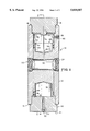
- FIG. 1 is a vertical section through a protective device according to the present invention.
- FIG. 2 is a view taken along lines 2--2 of FIG. 1.
- FIG. 3 is a schematic diagram of the device of FIGS. 1 and 2 incorporated into a pressure vessel fill protective system according to the present invention.
- FIG. 1 shows a protective device 10 according to the present invention.
- Device 10 includes a generally hollow cylindrical body 12 having a threaded first end 14 and a threaded second end 16 adapted to receive complimentary threaded caps 18 and 20 respectively.
- Body 12 includes diametrically opposed ports 22 and 24 threaded to receive conduits normally associated with filling a pressure vessel as will hereinafter be more fully explained.
- Piston 28 Disposed within body 12 is a generally cylindrical piston 28 having a first-end 30 and a second end 32.
- Piston 28 contains complimentary counter bores 34 and 36 on the first end 30 and the second end 32 respectively.
- Counter bore 34 includes a central aperture at the bottom 38 to receive a buckling pin 40 as will hereinafter be more fully explained.
- Piston 28 includes circumferential seals 42, 44 proximate the first end 30 and circumferential seals 46, 48 proximate second end 32.
- Piston 28 includes a central transverse passage 50 which is aligned with the ports 24 and 26 respectively when the piston is at the bottom of the housing 12 as shown in FIG. 1.
- Buckling pin 40 extends from the aperture 38 in the first end 30 of piston 28 to a slot or aperture 52 in top cap 18 so that the piston 28 can be held in the position shown when the device is assembled.
- Bottom cap 20 includes a central gas passage 54 which communicates with the counter bore 36 of piston 28.
- Passage 54 terminates at the outer or bottom surface 21 of cap 20 in a suitable threaded aperture 56.
- a passage 58 extends through the wall of body 12 to communicate with the upper displacement space 60 which is between the top end 30 of piston 38 and the bottom 19 of cap 18. Passage 58 terminates in a suitably threaded connection 62.
- buckling pin 40 instead of using buckling pin 40 as the means to position piston 28, one could use a spring.
- a guide slot 64 is machined in the bottom half of piston 28 of protective device 10.
- a locating pin, aperture 66 which is in the form of stepped cylinder, the larger cylindrical portion having suitable threads.
- a guide pin 68 in the form of a stepped cylinder complimentary in shape to the aperture 66 can be placed into the wall of the housing 12 to contact the slot 64 by means of a slotted aperture 70 and a screw driver (not shown). The purpose of the guide pin is to prevent rotation of the piston 28 as it moves in the housing 12.
- FIG. 3 shows an arrangement for installing the protective device 10 into a system used for filling a storage vessel such as a vacuum jacketed cryogenic storage vessel for storing liquid oxygen, nitrogen, argon or the like.
- a conduit represented by arrow 70 is fixed to the aperture (port) 22 and extends to the source of liquid cryogen (not shown). If the protective device 10 is installed on a customer station conduit 70 would be connected to a trailer hauled to the customers location, the trailer being filled with the liquid cryogen.
- a conduit represented by arrow 72 is connected to the port 24 and to the storage vessel (customer station) to be filled.
- a conduit 74 is fixed to the threaded aperture 56 and extends from aperture 56 to a normally open shutoff valve 76 which in turn is connected to the vapor space of the tank via a conduit represented by arrow 78.
- Conduit 80 is connected to aperture 62 and conduit 74 through a pressure drop or flow restricting device shown generally as 82 as is well known to a worker skilled in the art.
- a normally closed and locked valve 84 is connected to a series of conduits 86 and 88 to bypass the flow restricting device.
- a rupture disc 90 is disposed in conduit 80. Rupture disc 90 is set to actuate at the same pressure as the burst pressure discs contained in the customer station.
- Conduit 78 is connected to the vapor space of the tank being filled and valve 76 is in the locked open position and valve 84 is in the locked closed position.
- the piston is at the bottom of the body 12 so that when cryogen is flowing through conduit 70 it will flow through the device 10 into conduit 72 and into the tank to be filled.
- the space above the top end 30 of piston 22 will immediately be depressurized causing the higher pressure at the bottom 32 of piston 28 to cause the piston to move toward the top cap 18 thus shutting off fluid flow from the fill trailer to the customer station.
- the protective device 10 can be reset so that liquid cryogen can be introduced into the tank or customer station.
- the normally locked open valve 76 is closed and the rupture disc 90 replaced.
- the top cap 18 can be removed from the body 12 and the piston 28 returned to its position as shown in FIGS. 1 and 2.
- the buckling pin 40 can be replaced and the top cap 18 replaced thus aligning the passage 50 with the ports 22 and 24.
- the normally closed and locked valve 84 and the normally locked open valve 76 are opened slowly to provide means to bypass the pressure or flow restrictor 82 and to equalize the pressure in the system and protective device 10 during the resetting operation.
- normally locked open valve 76 is opened.
- the normally closed and locked valve can then be closed and locked and cryogen introduced into the inner vessel of the customer station until it is filled.
- a device according to the invention can be designed to actuate at 1.5 times the maximum allowable working pressure of the inner vessel of the customer station with a plus or minus 5% deviation which corresponds to the burst pressure of the tanks main rupture disc.
- a device according to the invention has been shown to actuate within three seconds to completely close off cryogenic liquid flow to the customer station after complete actuation.
- the body 12 end caps 18, 20 and piston 28 can be manufactured from brass and the buckling pin 40 from a copper or copper alloy as is well known in manufacturing devices for cryogenic service.
- over-pressurization in the vapor space of a tank to be protected causes a sequence of relatively few events to occur leading to rapid termination of liquid entering the vessel.
- the mechanical arrangement of the structural elements of the invention are highly reliable in design and function.
Landscapes
- Engineering & Computer Science (AREA)
- Mechanical Engineering (AREA)
- General Engineering & Computer Science (AREA)
- Filling Or Discharging Of Gas Storage Vessels (AREA)
Abstract
Description
Claims (7)
Priority Applications (1)
| Application Number | Priority Date | Filing Date | Title |
|---|---|---|---|
| US08/550,140 US5810057A (en) | 1995-10-30 | 1995-10-30 | Pressure vessel fill protective device |
Applications Claiming Priority (1)
| Application Number | Priority Date | Filing Date | Title |
|---|---|---|---|
| US08/550,140 US5810057A (en) | 1995-10-30 | 1995-10-30 | Pressure vessel fill protective device |
Publications (1)
| Publication Number | Publication Date |
|---|---|
| US5810057A true US5810057A (en) | 1998-09-22 |
Family
ID=24195913
Family Applications (1)
| Application Number | Title | Priority Date | Filing Date |
|---|---|---|---|
| US08/550,140 Expired - Fee Related US5810057A (en) | 1995-10-30 | 1995-10-30 | Pressure vessel fill protective device |
Country Status (1)
| Country | Link |
|---|---|
| US (1) | US5810057A (en) |
Cited By (5)
| Publication number | Priority date | Publication date | Assignee | Title |
|---|---|---|---|---|
| US6561714B1 (en) | 2000-11-20 | 2003-05-13 | Michael R. Williams | Breakaway joint for subsea components |
| US20070125425A1 (en) * | 2005-12-07 | 2007-06-07 | Carolan Michael F | Module isolation devices |
| US20110056566A1 (en) * | 2008-06-16 | 2011-03-10 | Cameron International Corporation | Dual-Acting Multi-Actuation Mode Gate Valve |
| EP2818777A1 (en) | 2013-06-28 | 2014-12-31 | Air Products And Chemicals, Inc. | Excess flow shutoff valve |
| US9255646B2 (en) | 2013-06-28 | 2016-02-09 | Air Products And Chemicals, Inc. | Excess flow shutoff valve |
Citations (4)
| Publication number | Priority date | Publication date | Assignee | Title |
|---|---|---|---|---|
| US3476133A (en) * | 1966-11-25 | 1969-11-04 | Gen Motors Corp | Valve operated by rate of fluid pressure change |
| US3930517A (en) * | 1974-06-11 | 1976-01-06 | Gagala Jerome W | Safety valve |
| US4522227A (en) * | 1983-05-10 | 1985-06-11 | Mylander Gerald D | Fill valve responsive to liquid level |
| US4913184A (en) * | 1989-08-31 | 1990-04-03 | Fallon Merton R | Flow control device |
-
1995
- 1995-10-30 US US08/550,140 patent/US5810057A/en not_active Expired - Fee Related
Patent Citations (4)
| Publication number | Priority date | Publication date | Assignee | Title |
|---|---|---|---|---|
| US3476133A (en) * | 1966-11-25 | 1969-11-04 | Gen Motors Corp | Valve operated by rate of fluid pressure change |
| US3930517A (en) * | 1974-06-11 | 1976-01-06 | Gagala Jerome W | Safety valve |
| US4522227A (en) * | 1983-05-10 | 1985-06-11 | Mylander Gerald D | Fill valve responsive to liquid level |
| US4913184A (en) * | 1989-08-31 | 1990-04-03 | Fallon Merton R | Flow control device |
Cited By (10)
| Publication number | Priority date | Publication date | Assignee | Title |
|---|---|---|---|---|
| US6561714B1 (en) | 2000-11-20 | 2003-05-13 | Michael R. Williams | Breakaway joint for subsea components |
| US20070125425A1 (en) * | 2005-12-07 | 2007-06-07 | Carolan Michael F | Module isolation devices |
| EP1795252A1 (en) * | 2005-12-07 | 2007-06-13 | Air Products and Chemicals, Inc. | Module isolation devices |
| AU2006246527B2 (en) * | 2005-12-07 | 2009-01-08 | Air Products And Chemicals, Inc. | Module isolation devices |
| US7703472B2 (en) | 2005-12-07 | 2010-04-27 | Air Products And Chemicals, Inc. | Module isolation devices |
| CN1978033B (en) * | 2005-12-07 | 2010-10-27 | 气体产品与化学公司 | Module separation equipment |
| US20110056566A1 (en) * | 2008-06-16 | 2011-03-10 | Cameron International Corporation | Dual-Acting Multi-Actuation Mode Gate Valve |
| US8616230B2 (en) * | 2008-06-16 | 2013-12-31 | Cameron International Corporation | Dual-acting multi-actuation mode gate valve |
| EP2818777A1 (en) | 2013-06-28 | 2014-12-31 | Air Products And Chemicals, Inc. | Excess flow shutoff valve |
| US9255646B2 (en) | 2013-06-28 | 2016-02-09 | Air Products And Chemicals, Inc. | Excess flow shutoff valve |
Similar Documents
| Publication | Publication Date | Title |
|---|---|---|
| CN101297150B (en) | Control member for filling and/or extracting pressurized gas, container and passage with such member | |
| US2677939A (en) | Liquefied gas container | |
| US4064907A (en) | Fill limiting filler valve unit | |
| US4191208A (en) | Automatic fill-stop valve | |
| US5259424A (en) | Method and apparatus for dispensing natural gas | |
| US5937895A (en) | Fail-safe delivery valve for pressurized tanks | |
| EP1534991B1 (en) | Multiple regulator vacuum delivery valve assembly | |
| US4562852A (en) | Safety valve | |
| US11384903B2 (en) | Cryogenic fluid storage tank | |
| CN113260809B (en) | Cryogenic fluid storage tank and method of filling the same | |
| US11480301B2 (en) | Cryogenic fluid storage tank | |
| CN1118855A (en) | Device for controlling gas distribution and gas bottle with same | |
| EP1828649B1 (en) | Pressurised fluid cylinders | |
| US5810057A (en) | Pressure vessel fill protective device | |
| IL144880A (en) | Sub-atmospheric gas delivery method and apparatus | |
| US5022423A (en) | Safety valve | |
| US4840057A (en) | Method and apparatus for testing relief valve | |
| WO2004065750A2 (en) | Multiple dispensing check valve delivery system | |
| EP3376013B1 (en) | Space conserving integrated cryogenic fluid delivery system | |
| US5107898A (en) | Pressure equalizing system and valve | |
| EP0013579A2 (en) | Head piece for a tank for liquefied gas | |
| US11692634B2 (en) | Bypass valve assembly with integrated flow control valve | |
| US4852387A (en) | Method for testing relief valve | |
| EP3699480B1 (en) | System, medical gas filler adapter and activation shaft for use in such a system | |
| US20030079781A1 (en) | Quick closing shut-off valve |
Legal Events
| Date | Code | Title | Description |
|---|---|---|---|
| AS | Assignment |
Owner name: AIR PRODUCTS AND CHEMICALS, INC., PENNSYLVANIA Free format text: ASSIGNMENT OF ASSIGNORS INTEREST;ASSIGNOR:WESTMAN, MARTIN ALFRED;REEL/FRAME:007759/0569 Effective date: 19951030 |
|
| FPAY | Fee payment |
Year of fee payment: 4 |
|
| FEPP | Fee payment procedure |
Free format text: PAYOR NUMBER ASSIGNED (ORIGINAL EVENT CODE: ASPN); ENTITY STATUS OF PATENT OWNER: LARGE ENTITY |
|
| FPAY | Fee payment |
Year of fee payment: 8 |
|
| REMI | Maintenance fee reminder mailed | ||
| LAPS | Lapse for failure to pay maintenance fees | ||
| STCH | Information on status: patent discontinuation |
Free format text: PATENT EXPIRED DUE TO NONPAYMENT OF MAINTENANCE FEES UNDER 37 CFR 1.362 |
|
| FP | Lapsed due to failure to pay maintenance fee |
Effective date: 20100922 |