US5810039A - Module for extracting fluid from a hollow vessel - Google Patents
Module for extracting fluid from a hollow vessel Download PDFInfo
- Publication number
- US5810039A US5810039A US08/514,470 US51447095A US5810039A US 5810039 A US5810039 A US 5810039A US 51447095 A US51447095 A US 51447095A US 5810039 A US5810039 A US 5810039A
- Authority
- US
- United States
- Prior art keywords
- module
- hollow vessel
- extension arm
- fluid
- attachment
- Prior art date
- Legal status (The legal status is an assumption and is not a legal conclusion. Google has not performed a legal analysis and makes no representation as to the accuracy of the status listed.)
- Expired - Lifetime
Links
Images
Classifications
-
- F—MECHANICAL ENGINEERING; LIGHTING; HEATING; WEAPONS; BLASTING
- F02—COMBUSTION ENGINES; HOT-GAS OR COMBUSTION-PRODUCT ENGINE PLANTS
- F02M—SUPPLYING COMBUSTION ENGINES IN GENERAL WITH COMBUSTIBLE MIXTURES OR CONSTITUENTS THEREOF
- F02M37/00—Apparatus or systems for feeding liquid fuel from storage containers to carburettors or fuel-injection apparatus; Arrangements for purifying liquid fuel specially adapted for, or arranged on, internal-combustion engines
- F02M37/04—Feeding by means of driven pumps
- F02M37/08—Feeding by means of driven pumps electrically driven
- F02M37/10—Feeding by means of driven pumps electrically driven submerged in fuel, e.g. in reservoir
- F02M37/103—Mounting pumps on fuel tanks
-
- B—PERFORMING OPERATIONS; TRANSPORTING
- B29—WORKING OF PLASTICS; WORKING OF SUBSTANCES IN A PLASTIC STATE IN GENERAL
- B29C—SHAPING OR JOINING OF PLASTICS; SHAPING OF MATERIAL IN A PLASTIC STATE, NOT OTHERWISE PROVIDED FOR; AFTER-TREATMENT OF THE SHAPED PRODUCTS, e.g. REPAIRING
- B29C49/00—Blow-moulding, i.e. blowing a preform or parison to a desired shape within a mould; Apparatus therefor
- B29C49/02—Combined blow-moulding and manufacture of the preform or the parison
- B29C49/04—Extrusion blow-moulding
-
- B—PERFORMING OPERATIONS; TRANSPORTING
- B29—WORKING OF PLASTICS; WORKING OF SUBSTANCES IN A PLASTIC STATE IN GENERAL
- B29C—SHAPING OR JOINING OF PLASTICS; SHAPING OF MATERIAL IN A PLASTIC STATE, NOT OTHERWISE PROVIDED FOR; AFTER-TREATMENT OF THE SHAPED PRODUCTS, e.g. REPAIRING
- B29C49/00—Blow-moulding, i.e. blowing a preform or parison to a desired shape within a mould; Apparatus therefor
- B29C49/20—Blow-moulding, i.e. blowing a preform or parison to a desired shape within a mould; Apparatus therefor of articles having inserts or reinforcements ; Handling of inserts or reinforcements
-
- B—PERFORMING OPERATIONS; TRANSPORTING
- B60—VEHICLES IN GENERAL
- B60K—ARRANGEMENT OR MOUNTING OF PROPULSION UNITS OR OF TRANSMISSIONS IN VEHICLES; ARRANGEMENT OR MOUNTING OF PLURAL DIVERSE PRIME-MOVERS IN VEHICLES; AUXILIARY DRIVES FOR VEHICLES; INSTRUMENTATION OR DASHBOARDS FOR VEHICLES; ARRANGEMENTS IN CONNECTION WITH COOLING, AIR INTAKE, GAS EXHAUST OR FUEL SUPPLY OF PROPULSION UNITS IN VEHICLES
- B60K15/00—Arrangement in connection with fuel supply of combustion engines or other fuel consuming energy converters, e.g. fuel cells; Mounting or construction of fuel tanks
- B60K15/03—Fuel tanks
- B60K15/077—Fuel tanks with means modifying or controlling distribution or motion of fuel, e.g. to prevent noise, surge, splash or fuel starvation
-
- F—MECHANICAL ENGINEERING; LIGHTING; HEATING; WEAPONS; BLASTING
- F02—COMBUSTION ENGINES; HOT-GAS OR COMBUSTION-PRODUCT ENGINE PLANTS
- F02M—SUPPLYING COMBUSTION ENGINES IN GENERAL WITH COMBUSTIBLE MIXTURES OR CONSTITUENTS THEREOF
- F02M37/00—Apparatus or systems for feeding liquid fuel from storage containers to carburettors or fuel-injection apparatus; Arrangements for purifying liquid fuel specially adapted for, or arranged on, internal-combustion engines
- F02M37/22—Arrangements for purifying liquid fuel specially adapted for, or arranged on, internal-combustion engines, e.g. arrangements in the feeding system
- F02M37/32—Arrangements for purifying liquid fuel specially adapted for, or arranged on, internal-combustion engines, e.g. arrangements in the feeding system characterised by filters or filter arrangements
-
- B—PERFORMING OPERATIONS; TRANSPORTING
- B29—WORKING OF PLASTICS; WORKING OF SUBSTANCES IN A PLASTIC STATE IN GENERAL
- B29C—SHAPING OR JOINING OF PLASTICS; SHAPING OF MATERIAL IN A PLASTIC STATE, NOT OTHERWISE PROVIDED FOR; AFTER-TREATMENT OF THE SHAPED PRODUCTS, e.g. REPAIRING
- B29C49/00—Blow-moulding, i.e. blowing a preform or parison to a desired shape within a mould; Apparatus therefor
- B29C49/20—Blow-moulding, i.e. blowing a preform or parison to a desired shape within a mould; Apparatus therefor of articles having inserts or reinforcements ; Handling of inserts or reinforcements
- B29C2049/2008—Blow-moulding, i.e. blowing a preform or parison to a desired shape within a mould; Apparatus therefor of articles having inserts or reinforcements ; Handling of inserts or reinforcements inside the article
-
- B—PERFORMING OPERATIONS; TRANSPORTING
- B29—WORKING OF PLASTICS; WORKING OF SUBSTANCES IN A PLASTIC STATE IN GENERAL
- B29L—INDEXING SCHEME ASSOCIATED WITH SUBCLASS B29C, RELATING TO PARTICULAR ARTICLES
- B29L2031/00—Other particular articles
- B29L2031/712—Containers; Packaging elements or accessories, Packages
- B29L2031/7172—Fuel tanks, jerry cans
-
- B—PERFORMING OPERATIONS; TRANSPORTING
- B60—VEHICLES IN GENERAL
- B60K—ARRANGEMENT OR MOUNTING OF PROPULSION UNITS OR OF TRANSMISSIONS IN VEHICLES; ARRANGEMENT OR MOUNTING OF PLURAL DIVERSE PRIME-MOVERS IN VEHICLES; AUXILIARY DRIVES FOR VEHICLES; INSTRUMENTATION OR DASHBOARDS FOR VEHICLES; ARRANGEMENTS IN CONNECTION WITH COOLING, AIR INTAKE, GAS EXHAUST OR FUEL SUPPLY OF PROPULSION UNITS IN VEHICLES
- B60K15/00—Arrangement in connection with fuel supply of combustion engines or other fuel consuming energy converters, e.g. fuel cells; Mounting or construction of fuel tanks
- B60K15/03—Fuel tanks
- B60K2015/03105—Fuel tanks with supplementary interior tanks inside the fuel tank
-
- B—PERFORMING OPERATIONS; TRANSPORTING
- B60—VEHICLES IN GENERAL
- B60K—ARRANGEMENT OR MOUNTING OF PROPULSION UNITS OR OF TRANSMISSIONS IN VEHICLES; ARRANGEMENT OR MOUNTING OF PLURAL DIVERSE PRIME-MOVERS IN VEHICLES; AUXILIARY DRIVES FOR VEHICLES; INSTRUMENTATION OR DASHBOARDS FOR VEHICLES; ARRANGEMENTS IN CONNECTION WITH COOLING, AIR INTAKE, GAS EXHAUST OR FUEL SUPPLY OF PROPULSION UNITS IN VEHICLES
- B60K15/00—Arrangement in connection with fuel supply of combustion engines or other fuel consuming energy converters, e.g. fuel cells; Mounting or construction of fuel tanks
- B60K15/03—Fuel tanks
- B60K2015/03236—Fuel tanks characterised by special filters, the mounting thereof
-
- Y—GENERAL TAGGING OF NEW TECHNOLOGICAL DEVELOPMENTS; GENERAL TAGGING OF CROSS-SECTIONAL TECHNOLOGIES SPANNING OVER SEVERAL SECTIONS OF THE IPC; TECHNICAL SUBJECTS COVERED BY FORMER USPC CROSS-REFERENCE ART COLLECTIONS [XRACs] AND DIGESTS
- Y10—TECHNICAL SUBJECTS COVERED BY FORMER USPC
- Y10T—TECHNICAL SUBJECTS COVERED BY FORMER US CLASSIFICATION
- Y10T137/00—Fluid handling
- Y10T137/0318—Processes
- Y10T137/0402—Cleaning, repairing, or assembling
- Y10T137/0441—Repairing, securing, replacing, or servicing pipe joint, valve, or tank
- Y10T137/048—With content loading or unloading [e.g., dispensing, discharge assistant, etc.]
-
- Y—GENERAL TAGGING OF NEW TECHNOLOGICAL DEVELOPMENTS; GENERAL TAGGING OF CROSS-SECTIONAL TECHNOLOGIES SPANNING OVER SEVERAL SECTIONS OF THE IPC; TECHNICAL SUBJECTS COVERED BY FORMER USPC CROSS-REFERENCE ART COLLECTIONS [XRACs] AND DIGESTS
- Y10—TECHNICAL SUBJECTS COVERED BY FORMER USPC
- Y10T—TECHNICAL SUBJECTS COVERED BY FORMER US CLASSIFICATION
- Y10T137/00—Fluid handling
- Y10T137/8593—Systems
- Y10T137/86348—Tank with internally extending flow guide, pipe or conduit
- Y10T137/86372—Inlet internally extending
Definitions
- the present invention concerns a module for extracting fluid from a hollow vessel.
- Hollow vessels for example tanks and bottles, are most often used to contain fluids to which they are substantially impermeable. These days thermoplastics are largely used to manufacture such hollow vessels due to their light weight, corrosion resistance, safety and ability to be easily formed into complex shapes.
- the object of the invention is, therefore, to define means as complete as possible which incorporate several functions for extracting fluid from a hollow vessel and which can be easily manufactured, handled and installed, and safety used.
- the invention concerns a module to be arranged within a hollow vessel for extracting fluid from the hollow vessel, the module comprising a pumping device, at least one filtering device and at least one extension arm which has means enabling connection with the outside of the module.
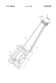
- the figure shows a module to be arranged within a thermoplastic fuel tank for extracting fuel from the fuel tank.
- the module includes an extracting pump (1), a fine filter (2) downstream of the pump, and two extension arms (3) and (4).
- the module also includes a fuel trap and support (5), and a pressure regulating device (6) downstream of the pump (1) and the filter (2).
- the two extension arms are joined and ended at one extremity by an attachment (8).
- the attachment comprises three orifices, one (9) for entry of an electrical cable, a second (10) for exit of the extracted fuel, and the third (11) for the blowing of the thermoplastic fuel tank during its blow molding and for filling the tank with fuel when in use.
- the module comprises a support together with at least the pumping device and the at least one filtering device. It could have been pre-assembled or produced as one integral unit.
- support is meant any means of attaching together at least the pumping device and the at least one filtering device such that they constitute a single entity and can be handled as such and installed in one step.
- the module is substantially rigid and remains only sufficiently flexible to allow its insertion and positioning in the hollow vessel.
- the purpose of the pumping device is for extracting fluid from the hollow vessel.
- the pumping device can be of any sort known to a practitioner in the art for the transportation of fluids. It can be selected and adapted to its specific function and in particular to the fluid to be extracted.
- At least one filtering device is present in the module. It can be of any sort know to a practitioner in the art for the removal of particles from a fluid passing through it. In particular, it can be conceived as a coarse or as a fine filtering device. Several filtering devices, in particular two, can be present in the module and used in combination.
- the pump device is connected in the module in series with the at least one filtering device, by any appropriate means, such that the fluid passing through the pumping device has passed or will pass through the at least one filtering device.
- at least one filtering device is upstream of the pumping device especially to protect it.
- a finer filtering device can be further present in the module downstream of the pumping device.
- the fluid can be a liquid or a gas. In particular, it is a liquid. More particularly, it is a fuel.
- the extension arm by itself, is substantially rigid and remains only sufficiently flexible to allow its insertion and positioning in the hollow vessel.
- Means of the extension arm enabling connection of the module with the outside can be of any type, such as among others a groove.
- means are fully integrated inside of the extension arm, in order to define an internal passage through the complete length of the extension arm.
- the extension arm has means enabling connection of the module with the outside of the module. After fixing of the module with the hollow vessel, they enable especially the connection of the module with the outside of the hollow vessel.
- connection of the module, by the extension arm, with the outside can be for any reason. Especially, it is for energy supply to the module or for fluid transfer.
- At least one extension arm has means enabling electrical connection of part of the module to an electrical supply outside of the module. More particularly, one extension arm has means enabling electrical connection of part of the module to an electrical supply outside of the module.
- electrical supply through the extension arm avoids the need for any supplementary means to do so, any further assembly of it and any further hole in the hollow vessel for the electrical supply. It enables for example the electrical supply of the pumping device.
- At least one extension arm is ended at one extremity by an attachment to be inserted in the wall of the hollow vessel.
- the extremity ended by this attachment is the extremity opposed to the extremity where are placed the pumping device and the at least one filtering device.
- the attachment comprises at least one orifice.
- Such an orifice can correspond to the prolongation of the means enabling connection with the outside of the module through an extension arm.
- Said orifice can also be independent of the means enabling connection with the outside of the module through an extension arm.
- the module advantageously comprises one or several additional elements.
- it also comprises at least part of a fluid trap to be placed in the hollow vessel to ensure pumping of the fluid in most of the possible use conditions of the hollow vessel.
- it comprises a complete fluid trap.
- the module can also comprise at least part of a fluid gauge which will indicate the fluid level in the hollow vessel after fixing of the module in it.
- the module further comprises a pressure regulating device. This pressure regulating device is directed to regulate the pressure in the fluid line and is placed downstream of the pumping device. It is possible integration in the module advantageously simplifies the later assembly of the complete fluid line.
- the module can also comprise at least one valve associated with the hollow vessel.
- the invention concerns a very interesting module for extracting fluid from a hollow vessel.
- a module for extracting fluid comprising a pumping device, at least one filtering device and at least one extension arm which has means enabling connection with the outside of the hollow vessel, the fixing taking place during the manufacturing of the hollow vessel.
- the hollow vessel can be of any material.
- it is essentially made of thermoplastic material.
- thermoplastic material is understood one or several thermoplastic polymers.
- the polymers can be homopolymers, copolymers or a suitable mixture of them. Typical examples could be polyolefins or polyvinyl chlorides. Good results have been obtained by using polyethylene. Excellent results have been obtained by using high density polyethylene (HDPE).
- the thermoplastic material can equally comprise one or several additives such an antioxydants, stabilisers, pigments etc.
- the hollow vessel can be manufactured from one thermoplastic material only or equally from several layers of different thermoplastic materials.
- the hollow vessel can be of any type, especially a flask or a tank. Typically, it could be a tank, in particular directed to be used in a vehicle. Specifically, the hollow vessel is a fuel tank.
- the hollow vessel can be manufactured by any process. When essentially made of thermoplastic material, it can especially be manufactured by welding of at least two parts previously obtained by injection. When essentially made of thermoplastic material, it can alternatively be obtained by injection- or extrusion-blow molding. Interesting results have been obtained when the manufacturing of the hollow vessel, essentially consisting of thermoplastic material, is by a process of extrusion-blow molding. In such an extrusion-blow molding process, a parison is extruded in an open mold, the module to be fixed is positioned in the parison, the mold is closed and the hollow vessel is blown.
- Fixing of the module within the hollow vessel during manufacturing of the hollow vessel can be made by any known process, among others by hot pressing of the module on at least part of a wall or on a specific place of the hollow vessel. Fixing can also be completed in a further step, for example by supplementary hot pressing, ultrasonic welding or their combination.
- the fixing of the module can in particular comprise fixing of at least part of its support or of the at least part of the fluid trap that it possibly comprises.
- the fixing of the module advantageously comprises the fixing of one end of the at least one extension arm by its positioning in the contacting surfaces of the parts.
- the extension arm can be used at last as part of the support for the module, in particular as the complete support for the module in the hollow vessel.
- At least one extension arm of the module is advantageously ended at one extremity by an attachment to be inserted in the wall of the hollow vessel.
- At least one extension arm of the module is ended at one extremity by an attachment, the attachment being inserted in the wall of the hollow vessel during its manufacturing in order to form part of the outside surface of said hollow vessel.
- the extension arm of the module can in particular constitute the complete support of the module inside of the hollow vessel during manufacturing of this hollow vessel, so avoiding any problem of inserting and removing a support during manufacturing of the hollow vessel.
- the attachment comprises at least one orifice.
- one said orifice of the attachment of at least one extension arm is used during manufacturing of the hollow vessel for blowing the hollow vessel.
- all other possible orifices must be obturated during the blowing of the hollow vessel or must be so small that they do not affect the blowing step.
- the attachment inserted in the surface of the hollow vessel forms part of the outside surface. Preferably, it completes the outside surface.
- the invention is also directed to a hollow vessel comprising within the hollow vessel a module for extracting fluid, the module comprising a pumping device, at least one filtering device and at least one extension arm which has means enabling connection with the outside of the hollow vessel.
- the hollow vessel is advantageously a fuel tank.
- the invention finally concerns in a method of extracting fluid from a hollow vessel, the improvement wherein the fluid is extracted by a module arranged within the hollow vessel comprising a pumping device, at least one filtering device and at least one extension arm which has an internal conduit enabling connection with the outside of the hollow vessel.
- At least one extension arm of the module is ended at one extremity by an attachment comprising at least one orifice and said orifice enables filling of the hollow vessel with the fluid.
- the module further to the above-mentioned advantages, enables by the same orifice in the attachment the possible blowing of the hollow vessel during manufacturing and filling of the hollow vessel with the fluid when in use.
- the figure shows a module to be arranged within a thermoplastic fuel tank for extracting fuel from said fuel tank, the module comprising an extracting pump (1), a fine filter (2) downstream the pump and two extension arms (3)(4). As illustrated, the module also comprises a fuel trap and support (5) and a pressure regulating device (6) downstream the pump (1) and the filter (2). A non illustrated coarse filter may also be installed in the module upstream the pump and underneath it.
- the extension arm (3) has a groove (7) for placing an electrical cable enabling electrical connection of the pump (1) to an electrical supply outside of the module and outside the fuel tank in which the module will be in use.
- the extension arm (4) has an internal conduit enabling extraction of the fuel from the module and from the tank to a feeding line of an engine.
- the two extension arms are joined and ended at one extremity by an attachment (8) to be inserted in the wall of the thermoplastic fuel tank during its blow molding.
- an attachment (8) to be inserted in the wall of the thermoplastic fuel tank during its blow molding.
- the module is fully supported inside of the fuel tank by the two extension arms, so avoiding any problem arising from its support by an additional mean.
- the attachment will complete the outside surface of the fuel tank.
- the attachment comprises three orifices, one (9) for the entry of the electrical cable, the second (10) for the exit of the extracted fuel and the third (11) for the blowing of the thermoplastic fuel tank during its blow molding and for filling the tank with fuel when in use.
Landscapes
- Engineering & Computer Science (AREA)
- Mechanical Engineering (AREA)
- Chemical & Material Sciences (AREA)
- Combustion & Propulsion (AREA)
- Life Sciences & Earth Sciences (AREA)
- Sustainable Energy (AREA)
- Sustainable Development (AREA)
- Manufacturing & Machinery (AREA)
- Transportation (AREA)
- General Engineering & Computer Science (AREA)
- Cooling, Air Intake And Gas Exhaust, And Fuel Tank Arrangements In Propulsion Units (AREA)
- Blow-Moulding Or Thermoforming Of Plastics Or The Like (AREA)
- Details Of Reciprocating Pumps (AREA)
- Separation Using Semi-Permeable Membranes (AREA)
- Containers Having Bodies Formed In One Piece (AREA)
Abstract
Description
Claims (6)
Priority Applications (6)
| Application Number | Priority Date | Filing Date | Title |
|---|---|---|---|
| US08/514,470 US5810039A (en) | 1995-08-11 | 1995-08-11 | Module for extracting fluid from a hollow vessel |
| EP19960202203 EP0758589B1 (en) | 1995-08-11 | 1996-08-06 | Module for extracting fluid from a hollow vessel |
| DE69616901T DE69616901T2 (en) | 1995-08-11 | 1996-08-06 | Unit for taking liquid from a hollow body |
| CA002183101A CA2183101A1 (en) | 1995-08-11 | 1996-08-09 | Module for extracting fluid from a hollow vessel |
| JP21272996A JPH09119374A (en) | 1995-08-11 | 1996-08-12 | Module for withdrawing fluid from hollow containers |
| JP2008196813A JP2008255998A (en) | 1995-08-11 | 2008-07-30 | Module for extracting fluid from a hollow container |
Applications Claiming Priority (1)
| Application Number | Priority Date | Filing Date | Title |
|---|---|---|---|
| US08/514,470 US5810039A (en) | 1995-08-11 | 1995-08-11 | Module for extracting fluid from a hollow vessel |
Publications (1)
| Publication Number | Publication Date |
|---|---|
| US5810039A true US5810039A (en) | 1998-09-22 |
Family
ID=24047301
Family Applications (1)
| Application Number | Title | Priority Date | Filing Date |
|---|---|---|---|
| US08/514,470 Expired - Lifetime US5810039A (en) | 1995-08-11 | 1995-08-11 | Module for extracting fluid from a hollow vessel |
Country Status (5)
| Country | Link |
|---|---|
| US (1) | US5810039A (en) |
| EP (1) | EP0758589B1 (en) |
| JP (2) | JPH09119374A (en) |
| CA (1) | CA2183101A1 (en) |
| DE (1) | DE69616901T2 (en) |
Cited By (2)
| Publication number | Priority date | Publication date | Assignee | Title |
|---|---|---|---|---|
| US20140311584A1 (en) * | 2011-05-13 | 2014-10-23 | Jlmd Ecologic Group | Method for discharging liquid from a tank of a stricken ship |
| CN112497714A (en) * | 2020-10-30 | 2021-03-16 | 吴嘉文 | Blow molding machine |
Families Citing this family (6)
| Publication number | Priority date | Publication date | Assignee | Title |
|---|---|---|---|---|
| US5931353A (en) * | 1997-04-28 | 1999-08-03 | Solvay (Societe Anonyme) | Plastic hollow body with internal fastening arrangement |
| FR2779772B1 (en) * | 1998-06-16 | 2000-09-01 | Marwal Systems | LIQUID PUMP ASSEMBLY, PARTICULARLY FOR FUEL ADDITIVE |
| GB2388087A (en) * | 2002-05-03 | 2003-11-05 | Bamford Excavators Ltd | Containers |
| DE10260953B4 (en) * | 2002-12-20 | 2010-07-01 | Kautex Textron Gmbh & Co Kg | Fuel tank with functional component carrier and carrier for functional components of a motor vehicle fuel tank |
| RU2241849C2 (en) * | 2003-06-04 | 2004-12-10 | Общество с ограниченной ответственностью Завод электроагрегатного машиностроения "СЭПО-ЗЭМ" акционерного общества "Саратовское электроагрегатное производственное объединение" | Automobile fuel-feed module |
| FR2890341B1 (en) * | 2005-09-02 | 2008-10-24 | Inergy Automotive Systems Res | FUEL SYSTEM COMPRISING A FUEL RESERVE AND A RETENTION CONTAINER |
Citations (4)
| Publication number | Priority date | Publication date | Assignee | Title |
|---|---|---|---|---|
| WO1980000326A1 (en) * | 1978-07-28 | 1980-03-06 | Transformat Mat Plastiques | Method for obtaining a one piece cast hollow body by blowing |
| US4869225A (en) * | 1987-10-26 | 1989-09-26 | Nippondenso Co., Ltd. | Fuel supply device for vehicles |
| US5058557A (en) * | 1989-12-13 | 1991-10-22 | Robert Bosch Gmbh | Apparatus for delivery of fuel from a storage tank to an internal combustion engine of a vehicle |
| US5080077A (en) * | 1990-06-01 | 1992-01-14 | General Motors Corporation | Modular fuel delivery system |
Family Cites Families (7)
| Publication number | Priority date | Publication date | Assignee | Title |
|---|---|---|---|---|
| FR2584660A1 (en) * | 1985-07-09 | 1987-01-16 | Techni Plaste Ind | Fuel tank for motor vehicles and method for obtaining it |
| JP2537660B2 (en) * | 1988-05-28 | 1996-09-25 | 豊田合成株式会社 | Manufacturing method of synthetic resin fuel tank |
| JP2696975B2 (en) * | 1988-08-23 | 1998-01-14 | 新神戸電機株式会社 | Lead-acid battery group welding method |
| US5038741A (en) * | 1990-04-13 | 1991-08-13 | Walbro Corporation | In-tank fuel module |
| JP2875356B2 (en) * | 1990-06-22 | 1999-03-31 | 田淵 和久 | Sitting table |
| DE4140961A1 (en) * | 1991-12-12 | 1993-06-17 | Bosch Gmbh Robert | Electrohydraulic unit for electro fuel pump for motor vehicle - has hydraulic line and current lead connected to one head coupled to connector to make hydraulic and electric connection |
| ITTO920281A1 (en) * | 1992-03-27 | 1993-09-27 | Siceb Spa | SUPPORT FOR THE SUCTION PIPE OF A FUEL PUMP, PARTICULARLY FOR AN INTERNAL COMBUSTION ENGINE |
-
1995
- 1995-08-11 US US08/514,470 patent/US5810039A/en not_active Expired - Lifetime
-
1996
- 1996-08-06 DE DE69616901T patent/DE69616901T2/en not_active Expired - Lifetime
- 1996-08-06 EP EP19960202203 patent/EP0758589B1/en not_active Expired - Lifetime
- 1996-08-09 CA CA002183101A patent/CA2183101A1/en not_active Abandoned
- 1996-08-12 JP JP21272996A patent/JPH09119374A/en active Pending
-
2008
- 2008-07-30 JP JP2008196813A patent/JP2008255998A/en active Pending
Patent Citations (4)
| Publication number | Priority date | Publication date | Assignee | Title |
|---|---|---|---|---|
| WO1980000326A1 (en) * | 1978-07-28 | 1980-03-06 | Transformat Mat Plastiques | Method for obtaining a one piece cast hollow body by blowing |
| US4869225A (en) * | 1987-10-26 | 1989-09-26 | Nippondenso Co., Ltd. | Fuel supply device for vehicles |
| US5058557A (en) * | 1989-12-13 | 1991-10-22 | Robert Bosch Gmbh | Apparatus for delivery of fuel from a storage tank to an internal combustion engine of a vehicle |
| US5080077A (en) * | 1990-06-01 | 1992-01-14 | General Motors Corporation | Modular fuel delivery system |
Cited By (4)
| Publication number | Priority date | Publication date | Assignee | Title |
|---|---|---|---|---|
| US20140311584A1 (en) * | 2011-05-13 | 2014-10-23 | Jlmd Ecologic Group | Method for discharging liquid from a tank of a stricken ship |
| US9446819B2 (en) * | 2011-05-13 | 2016-09-20 | Jlmd Ecologic Group | Method for discharging liquid from a tank of a stricken ship |
| CN112497714A (en) * | 2020-10-30 | 2021-03-16 | 吴嘉文 | Blow molding machine |
| CN112497714B (en) * | 2020-10-30 | 2024-01-12 | 东莞市悦而实业有限公司 | Blow molding machine |
Also Published As
| Publication number | Publication date |
|---|---|
| JPH09119374A (en) | 1997-05-06 |
| DE69616901T2 (en) | 2002-08-29 |
| EP0758589A2 (en) | 1997-02-19 |
| DE69616901D1 (en) | 2001-12-20 |
| JP2008255998A (en) | 2008-10-23 |
| CA2183101A1 (en) | 1997-02-12 |
| EP0758589B1 (en) | 2001-11-14 |
| EP0758589A3 (en) | 1998-04-29 |
Similar Documents
| Publication | Publication Date | Title |
|---|---|---|
| JP2008255998A (en) | Module for extracting fluid from a hollow container | |
| US6851396B2 (en) | On-board fuel feed system for a motor vehicle | |
| US20120037638A1 (en) | Plastic fuel tank with improved creep resistance and method for the manufacture thereof | |
| US5797373A (en) | Fuel feeding device of motor vehicle | |
| US8372331B2 (en) | Process for manufacturing a plastic fuel tank | |
| CN101622484B (en) | Venting tubing system for a fuel tank | |
| US8631556B2 (en) | Process for manufacturing a plastic fuel tank equipped with a pump | |
| ITBO20070659A1 (en) | EQUIPMENT FOR THE SUPPLY OF FUEL, IN PARTICULAR LPG, TO AN INTERNAL COMBUSTION ENGINE. | |
| ATE380702T1 (en) | CLOSURE DEVICE FOR A FILLING PIPE OF A LIQUID TANK, TANK EQUIPPED WITH SUCH A DEVICE | |
| US8209854B2 (en) | Method for manufacturing a plastic fuel tank | |
| US20110220226A1 (en) | Fuel tank comprising a ventilation system equipped with a liquid/vapor separator | |
| JP3015102B2 (en) | Float valve for filling system, especially for electric traction battery | |
| CN112090657A (en) | Factice spraying device for optical cable manufacturing and using method thereof | |
| US20090107580A1 (en) | Electronic Refueling and Vent Control System with Integrated Control | |
| US20090295026A1 (en) | System for supplying an internal combustion engine and method of manufacturing a tank comprised in the system | |
| EP1747111B1 (en) | Fuel system | |
| JPH07223446A (en) | Fuel tank | |
| CN109854546A (en) | A kind of locomotive heating fuel tank device | |
| US5899227A (en) | Air transfer valve for fuel storage tanks | |
| CN105829155B (en) | Tank with internal connecting parts and method for assembling such tank | |
| CN100436186C (en) | A filling pipe equipped with an additive container and its manufacturing method | |
| US20050145316A1 (en) | Attaching dissimilar materials to a fuel tank by weldment | |
| JP2004011419A (en) | Pipe joint for resin tank | |
| KR20060015566A (en) | Additive reservoir for fuel system and manufacturing method of such reservoir | |
| JPH08238943A (en) | Breather device for fuel tank |
Legal Events
| Date | Code | Title | Description |
|---|---|---|---|
| AS | Assignment |
Owner name: SOLVAY (SOCIETE ANONYME), BELGIUM Free format text: ASSIGNMENT OF ASSIGNORS INTEREST;ASSIGNORS:WOOTERS, PAUL;HORE, GEORGES;OBSOMER, MARC;REEL/FRAME:007759/0301 Effective date: 19951004 |
|
| STCF | Information on status: patent grant |
Free format text: PATENTED CASE |
|
| FPAY | Fee payment |
Year of fee payment: 4 |
|
| AS | Assignment |
Owner name: INERGY AUTOMOTIVE SYSTEMS RESEARCH, BELGIUM Free format text: ASSIGNMENT OF ASSIGNORS INTEREST;ASSIGNOR:SOLVAY (SOCIETE ANONYME);REEL/FRAME:014267/0853 Effective date: 20030714 |
|
| AS | Assignment |
Owner name: FUSION DISTRIBUTORS LLC, CONNECTICUT Free format text: ASSIGNMENT OF ASSIGNORS INTEREST;ASSIGNOR:MEDIA GROUP;REEL/FRAME:014588/0495 Effective date: 20030909 |
|
| AS | Assignment |
Owner name: MEDIA GROUP, INC., THE, CONNECTICUT Free format text: ASSIGNMENT OF ASSIGNORS INTEREST;ASSIGNOR:FUSION DISTRIBUTORS LLC;REEL/FRAME:015377/0527 Effective date: 20040728 |
|
| FPAY | Fee payment |
Year of fee payment: 8 |
|
| FPAY | Fee payment |
Year of fee payment: 12 |