US580771A - Riveting-machine - Google Patents
Riveting-machine Download PDFInfo
- Publication number
- US580771A US580771A US580771DA US580771A US 580771 A US580771 A US 580771A US 580771D A US580771D A US 580771DA US 580771 A US580771 A US 580771A
- Authority
- US
- United States
- Prior art keywords
- cylinder
- piston
- plunger
- valve
- frame
- Prior art date
- Legal status (The legal status is an assumption and is not a legal conclusion. Google has not performed a legal analysis and makes no representation as to the accuracy of the status listed.)
- Expired - Lifetime
Links
Images


Classifications
-
- B—PERFORMING OPERATIONS; TRANSPORTING
- B60—VEHICLES IN GENERAL
- B60T—VEHICLE BRAKE CONTROL SYSTEMS OR PARTS THEREOF; BRAKE CONTROL SYSTEMS OR PARTS THEREOF, IN GENERAL; ARRANGEMENT OF BRAKING ELEMENTS ON VEHICLES IN GENERAL; PORTABLE DEVICES FOR PREVENTING UNWANTED MOVEMENT OF VEHICLES; VEHICLE MODIFICATIONS TO FACILITATE COOLING OF BRAKES
- B60T13/00—Transmitting braking action from initiating means to ultimate brake actuator with power assistance or drive; Brake systems incorporating such transmitting means, e.g. air-pressure brake systems
- B60T13/10—Transmitting braking action from initiating means to ultimate brake actuator with power assistance or drive; Brake systems incorporating such transmitting means, e.g. air-pressure brake systems with fluid assistance, drive, or release
- B60T13/24—Transmitting braking action from initiating means to ultimate brake actuator with power assistance or drive; Brake systems incorporating such transmitting means, e.g. air-pressure brake systems with fluid assistance, drive, or release the fluid being gaseous
- B60T13/46—Vacuum systems
- B60T13/52—Vacuum systems indirect, i.e. vacuum booster units
- B60T13/565—Vacuum systems indirect, i.e. vacuum booster units characterised by being associated with master cylinders, e.g. integrally formed
Definitions
- My invention relates to a machine especiall y adapted for riveting, but which may be adapted to punching and shearing by substitutin g for the rivets punching-dies or shearblades.
- the object of my invention is to so design the machine that it will be simple in construction and effective in its work and can be readily taken apart for repairs and which will use the operating fluid. economically.
- Figure 1 is a side View, partly in section, illustrating my improved riveting-machine.
- Fig. 2 is a plan View.
- Fig. 3 is a rear View.
- Fig. 4 is a sectional View through the valve and casing, and
- Fig. 5 is a view of a modification.
- a in the present instance is a yoke-frame made in a single casting having two arms a a, and on the lower arm a is a block a shaped to correspond to the head of the rivet.
- Screwed into the arm a, in the present in stance is a cylinder B, in which is a plunger 13, having at one end a die or dolly 1), adapted to form the rivet.
- a plunger 13 having at one end a die or dolly 1
- suitable packing On the opposite end of the plunger is suitable packing to prevent the fluid leaking past the plunger.
- a cylinder D Secured to the rear of the yoke-frame is a cylinder D, having an extension d, preferably shaped as shown in the accompanying drawings, and D is a fixed plunger screwed into the rear of the cylinder-casing.
- This plunger has packing d at its inner end and has apassage d communicating with the passage (1 in the casing, which communicates in turn with the passage in the tubular connection E,which is coupled to the cylinder B.
- This piston F is apiston, preferably of the shape shown, its rim being provided with suitable packing, so as to fit snugly within the cylinder.
- This piston has a center projection forming a cylinder F, which is adapted to a bushing c in the frame A.
- This frame has an extension 0. projecting into the cylinder D, as shown in Fig. 1, so as to give full bearing to the bushing c.
- the piston-cylinder is closed at one end, and the fixed plunger D is adapted to this piston-cylinder, as shown.
- the object of this construction is to transmit the pressure exerted upon the piston through the liquid contained within the piston-cylinder, passage in the plunger, the tube, and the cylinder B to the plunger B.
- valve mechanism Any form of valve mechanism may be used, but I prefer the one which I will now proceed to describe.
- I is the valve-chamber, in which is a valve J of the cylindrical type.
- This valve has a central inlet-passagej, an exhaust-channelj, and a passage j i 1 are passages leading from the ends of the cylinder D to the ports of the valvechamber I.
- L is an inlet-pipe, and Lthe exhaust communicatin g with the valve-chamber, asshown in Fig. i.
- the valve is in the position shown in Fig. 4, air under pressure is admitted to the forward end of the cylinder D and exhausted from the rear end.
- the two ends of the cylinder D communicate and the inlet and exhaust pipes are closed to the cylinder D, so as to allow the air in the forward end of the cylinder, after it has actuated the piston, to flow into the rear end of the cylinder through the passage 1', so as to return the piston to its normal position at the forward end of the cylinder. This is accomplished owing to the fact that the area of the rear of the piston acted upon by the air is greater than that at the front.
- the valve J has a spindle J and a hand- Wheel J
- the valve has preferably a slight taper and is held in place by a screw-plug i between which and the valve is a spring 1.
- the pressure ofair against the valve tends to counteract the pressure of the spring and to allow the valve to be readily turned; but the spring will always tend to keep the valve to its seat.
- the machine is suspended from a yokeframe M, attached to trunnions m m on each side of the frame, as clearly shown in Fig. 3, although it may be supported by a suitable base when used, in the fixed position and in some instances, when 'made in the smaller sizes, may be held in the hand.
- the spindle D can be removed from the cylinder for the replacement of the packingrings when necessary without dismantling the machine, so that the tight joint is always insured between the piston and the fixed spindle.
- the position of rest of the plunger B is regulated by a screw S, which is adapted to a screw-plug s in the end of the cylinder B, and between this screw-plug and a flange on the cylinder is a packing-ring, so as to keep this joint always tight.
- a machine built according to my invention can be operated by compressed air, steam, or other fluid under pressure, and I prefer to use in the cylinder B and passages and in the cylinder of the piston a liquid, such as oil and tallow or glycerin.
- the fixed spindle D instead of being secured to the rear of the cylinder, may be secured to the frame, as shown in Fig. 5, and. the short connection made between it and the cylinder B without departing from the main features of my invention.
Landscapes
- Engineering & Computer Science (AREA)
- Transportation (AREA)
- Mechanical Engineering (AREA)
- Actuator (AREA)
Description
(No Model.) 4 Sheets-"Sheet 3. S. S. GASKEY.
RIVBTING MACHINE. No. 580,771. Patented Apr. 13,,1897.
UNITED STATES PATENT OFFICE.
SAMUEL S. CASKEY, OF. PHILADELPHIA, PENNSYLVANIA.
RlVETlNG-IVIACHINE.
SPECIFICATION forming part of Letters Patent No. 580,771, dated April 13, 1897.
Application filed July 23, 1896. Serial No. 600,305. (No model.)
To all whom it may concern:
Be it known that I, SAMUEL S. CAsKEY, a citizen of the United States, residing in Philadelphia, Pennsylvania, have invented certain Improvements in Riveting-Machines, of which the following is a specification.
My invention relates to a machine especiall y adapted for riveting, but which may be adapted to punching and shearing by substitutin g for the rivets punching-dies or shearblades.
The object of my invention is to so design the machine that it will be simple in construction and effective in its work and can be readily taken apart for repairs and which will use the operating fluid. economically.
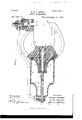
In the accompanying drawings, Figure 1 is a side View, partly in section, illustrating my improved riveting-machine. Fig. 2 is a plan View. Fig. 3 is a rear View. Fig. 4 is a sectional View through the valve and casing, and Fig. 5 is a view of a modification.
A in the present instance is a yoke-frame made in a single casting having two arms a a, and on the lower arm a is a block a shaped to correspond to the head of the rivet. Screwed into the arm a, in the present in stance is a cylinder B, in which is a plunger 13, having at one end a die or dolly 1), adapted to form the rivet. On the opposite end of the plunger is suitable packing to prevent the fluid leaking past the plunger.
Secured to the rear of the yoke-frame is a cylinder D, having an extension d, preferably shaped as shown in the accompanying drawings, and D is a fixed plunger screwed into the rear of the cylinder-casing. This plunger has packing d at its inner end and has apassage d communicating with the passage (1 in the casing, which communicates in turn with the passage in the tubular connection E,which is coupled to the cylinder B.
F is apiston, preferably of the shape shown, its rim being provided with suitable packing, so as to fit snugly within the cylinder. This piston has a center projection forming a cylinder F, which is adapted to a bushing c in the frame A. This frame has an extension 0. projecting into the cylinder D, as shown in Fig. 1, so as to give full bearing to the bushing c. The piston-cylinder is closed at one end, and the fixed plunger D is adapted to this piston-cylinder, as shown. The object of this construction is to transmit the pressure exerted upon the piston through the liquid contained within the piston-cylinder, passage in the plunger, the tube, and the cylinder B to the plunger B.
Any form of valve mechanism may be used, but I prefer the one which I will now proceed to describe.
I is the valve-chamber, in which is a valve J of the cylindrical type. This valve has a central inlet-passagej, an exhaust-channelj, and a passage j i 1 are passages leading from the ends of the cylinder D to the ports of the valvechamber I. r
L is an inlet-pipe, and Lthe exhaust communicatin g with the valve-chamber, asshown in Fig. i.
\Vhen the valve is in the position shown in Fig. 4, air under pressure is admitted to the forward end of the cylinder D and exhausted from the rear end. When it is turned onequarter, the two ends of the cylinder D communicate and the inlet and exhaust pipes are closed to the cylinder D, so as to allow the air in the forward end of the cylinder, after it has actuated the piston, to flow into the rear end of the cylinder through the passage 1', so as to return the piston to its normal position at the forward end of the cylinder. This is accomplished owing to the fact that the area of the rear of the piston acted upon by the air is greater than that at the front.
The valve J has a spindle J and a hand- Wheel J The valve has preferably a slight taper and is held in place by a screw-plug i between which and the valve is a spring 1. The pressure ofair against the valve tends to counteract the pressure of the spring and to allow the valve to be readily turned; but the spring will always tend to keep the valve to its seat.
The machine is suspended from a yokeframe M, attached to trunnions m m on each side of the frame, as clearly shown in Fig. 3, although it may be supported by a suitable base when used, in the fixed position and in some instances, when 'made in the smaller sizes, may be held in the hand.
The spindle D can be removed from the cylinder for the replacement of the packingrings when necessary without dismantling the machine, so that the tight joint is always insured between the piston and the fixed spindle.
The position of rest of the plunger B is regulated by a screw S, which is adapted to a screw-plug s in the end of the cylinder B, and between this screw-plug and a flange on the cylinder is a packing-ring, so as to keep this joint always tight.
By simply adjusting the screw S the fluid in the cylinder B is displaced, and this screw can be utilized also to take up lost motion owing to leakage that may occur.
It will be seen that a machine built according to my invention can be operated by compressed air, steam, or other fluid under pressure, and I prefer to use in the cylinder B and passages and in the cylinder of the piston a liquid, such as oil and tallow or glycerin.
By constructing the cylinder and its piston in the manner shown I am enabled to use the compressed air, by which I prefer to operate the device, in the most economical manner, as the air which is used to move the plunger forward to compress the rivet is allowed to flow into the opposite end of the cylinder, so that the pressure at both ends of the cylinder is equalized, but the piston will be moved back to its normal position, owing to the difference in area.
In some instances the fixed spindle D, instead of being secured to the rear of the cylinder, may be secured to the frame, as shown in Fig. 5, and. the short connection made between it and the cylinder B without departing from the main features of my invention.
I claim as my inventionl. The combination of the frame, its cylinder, a plunger adapted to the cylinder having a riveting-die, a tube for liquid, a compression-cylinder adapted to receive fluid under pressure, a piston in said cylinder and a cylinder carried by the piston and connected with the tube, the area of the back of the piston being greater than the front, a valve having a communicating passage so that the air after compressing a rivet will pass into the opposite end of the cylinder so that the piston and the plunger will be moved back to the normal position, substantially as described.
2. The combination of a frame A, its cylinder B, a plunger B', a cylinder D at the back of the yoke-frame, a fixed plunger D extending into the cylinder, a piston having a cylinder adapted to an opening in the frame and to the fixed plunger, said piston-cylinder communicating with the cylinder B through a passage, said passage containing liquid so that on the movement of the piston within its cylinder the plunger will be operated through the medium of the liquid, substantially as described.
3. The combination of the frame, the cylinder B, its piston B, a cylinder D secured to the rear of the frame and having a reduced extension, a plunger screwed into said extension and projecting into the cylinder and having a passage, a pipe forming communication between said passage and the cylinder B, a piston adapted to the cylinder D and having a central cylinder adapted to an opening in the frame and to the fixed plunger and communicating with the passage in the plunger, with valve mechanism cont-rolling the flow of fluid into the cylinderD, substantially as described.
4:. The combination of the yoke-frame having two arms a a and a rear extension a a cylinder on the arm a, a plunger in said cylinder, a cylinder D secured to the rear of the frame and inclosing'the extension a an opening in the extension, a piston F adapted to the cylinder and having a cylinder adapted to the opening in the extension, a hollow fixed plunger secured to the rear of the cylinder D and a tube communicating with the plunger and the cylinder B, and valve mechanism for controlling the movement of the piston F, substantially as described.
In testimonywhereof I have signed my name to this specification in the presence of two subscribing witnesses.
SAMUEL S. CASKEY.
Witnesses:
WILL. A. BARR, J 0s. H. KLEIN.
Publications (1)
| Publication Number | Publication Date |
|---|---|
| US580771A true US580771A (en) | 1897-04-13 |
Family
ID=2649449
Family Applications (1)
| Application Number | Title | Priority Date | Filing Date |
|---|---|---|---|
| US580771D Expired - Lifetime US580771A (en) | Riveting-machine |
Country Status (1)
| Country | Link |
|---|---|
| US (1) | US580771A (en) |
Cited By (3)
| Publication number | Priority date | Publication date | Assignee | Title |
|---|---|---|---|---|
| US3000242A (en) * | 1957-03-08 | 1961-09-19 | Harry B Barrett | Riveting machine |
| US20050081360A1 (en) * | 2001-01-15 | 2005-04-21 | Newfrey Llc | Method for riveting or piercing and a device for carrying out the method |
| US7163247B2 (en) | 1998-06-18 | 2007-01-16 | C-Power Technologies Ab | Tool holder |
-
0
- US US580771D patent/US580771A/en not_active Expired - Lifetime
Cited By (4)
| Publication number | Priority date | Publication date | Assignee | Title |
|---|---|---|---|---|
| US3000242A (en) * | 1957-03-08 | 1961-09-19 | Harry B Barrett | Riveting machine |
| US7163247B2 (en) | 1998-06-18 | 2007-01-16 | C-Power Technologies Ab | Tool holder |
| US20050081360A1 (en) * | 2001-01-15 | 2005-04-21 | Newfrey Llc | Method for riveting or piercing and a device for carrying out the method |
| US7082663B2 (en) | 2001-01-15 | 2006-08-01 | Newfrey Llc | Method for riveting or piercing and a device for carrying out the method |
Similar Documents
| Publication | Publication Date | Title |
|---|---|---|
| US3362618A (en) | Device for increasing pressure of working medium | |
| US791075A (en) | Pneumatic attachment for riveting and plate-closing machines. | |
| US1007792A (en) | Press. | |
| US772842A (en) | Double-acting equalizing-cylinder for fluid-pressure systems. | |
| US580294A (en) | Check-valve | |
| US1103020A (en) | Fluid-pressure-regulating mechanism. | |
| US516410A (en) | Air-pump for forcing beer | |
| US756993A (en) | Valve mechanism for pumps. | |
| US822519A (en) | Pump-governor. | |
| US899585A (en) | Gas-pump. | |
| US1182372A (en) | Air-compressing pump. | |
| US619534A (en) | berrier | |
| US813008A (en) | Pumping apparatus. | |
| US534340A (en) | moore | |
| US557511A (en) | Air-brake | |
| US971585A (en) | Counterbalancing device. | |
| US944221A (en) | Water-motor. | |
| US170008A (en) | Improveivjent in steam-pumps | |
| US588735A (en) | Blower and exhauster | |
| US53067A (en) | Improved steam-injected water-motor | |
| US165135A (en) | Improvement in riveting-machines | |
| US1073831A (en) | Power-press. | |
| US564522A (en) | Fluid-pressure brake | |
| US216030A (en) | Improvement in oscillating valves | |
| US1086047A (en) | Engine. |