US580747A - wright - Google Patents
wright Download PDFInfo
- Publication number
- US580747A US580747A US580747DA US580747A US 580747 A US580747 A US 580747A US 580747D A US580747D A US 580747DA US 580747 A US580747 A US 580747A
- Authority
- US
- United States
- Prior art keywords
- wire
- standard
- screw
- shoulder
- gong
- Prior art date
- Legal status (The legal status is an assumption and is not a legal conclusion. Google has not performed a legal analysis and makes no representation as to the accuracy of the status listed.)
- Expired - Lifetime
Links
- 238000010276 construction Methods 0.000 description 8
- 230000027455 binding Effects 0.000 description 3
- 230000002459 sustained effect Effects 0.000 description 3
- 239000002184 metal Substances 0.000 description 2
- 210000004761 scalp Anatomy 0.000 description 2
- 239000012141 concentrate Substances 0.000 description 1
- 235000009508 confectionery Nutrition 0.000 description 1
- 230000000694 effects Effects 0.000 description 1
- 238000004519 manufacturing process Methods 0.000 description 1
Images

Classifications
-
- G—PHYSICS
- G04—HOROLOGY
- G04B—MECHANICALLY-DRIVEN CLOCKS OR WATCHES; MECHANICAL PARTS OF CLOCKS OR WATCHES IN GENERAL; TIME PIECES USING THE POSITION OF THE SUN, MOON OR STARS
- G04B21/00—Indicating the time by acoustic means
- G04B21/02—Regular striking mechanisms giving the full hour, half hour or quarter hour
- G04B21/08—Sounding bodies; Whistles; Musical apparatus
Definitions
- W'ILIJIAM II WRIGI-IT, OF BRISTOL, CONNECTICUT, ASSIGNOR TO THE E. INGRAIIAM COMPANY, OF SAME PLACE.
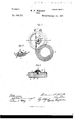
- Figure l a plan view of a clock-bell constructed in accordance with my invention
- Fig. 2 a View thereof on the line a I) of Fig. l
- Fig. 3 a broken View, partly in elevation and partly in section, on the line c d of Fig. l
- Fig. Ll a plan View of another form which my improved bell mayassume
- Fig. 5, aview thereof, in central section, on the line c j' of Fig. 4.
- Y a plan view of a clock-bell constructed in accordance with my invention
- My invention relates to an improvement in that class of bells for clocks which comprise a spirally-coiled wire forming a gong and a standard to which one end of the same is secured.
- the object of my present invention is to overcome the objections before encountered and to secure at a low cost for manufacture a wire bell or gong which will ring without twangin g and with a pure deep-toned sustained note with the effect of adistant chime.
- I flatten the outer end of the spring A, so as to virtually form a double shoulder A, markedly increasing the width of the Wire at the point attened.
- I also form a cast-metal standard B with a central hub or boss B', having a groove or slot B2 formed in it to receive the endof the wire and also a screw-hole B3 to receive the binding screw C, by means of which the washer D is drawn down upon the face of the hub and the upper edge of the end of the wire in the groove B2 thereof.
- the standard is furnished with a scalp E, which is struck up to Iit over the hub and into the recess B2; but this scalp may be dispensed with, if desired, its function being purely ornamental.
- the outer end of the wire is inserted into the groove B2 thereof and under the edge of the washer, so that the outer end of the shoulder is just entered into the groove and under the adjacent edge of the washer, which is thus slightly tilted.
- the screw C is then turned down to tighten the washer, which, instead of exerting a uniform downward pressure throughout that portion of the wire under it and in the groove, concentrates its pressure upon the wire at the point where the shoulder is entered into the groove and under the edge of the washer.
- a standard constructed with a central boss, having a screw-hole formed in its center, and having a groove or slot formed in it adjacent to but one side of the said screw-hole; of a coiled wire forming av gong, having its outer end made straight to enter the said slot in the boss of the washer, and flattened to form a shoulder Which is entered into one end of the said slot, a Washer which is placed upon the said boss, and adapted to engage with the said outer end of the gong, and with the outer end of the shoulder thereof, and a bindingscrew passing down .through the said washer, and into the screw-hole of the boss of the standard and concentrating its binding action upon the said shoulder by means of which an intimate relation-between the gong and standard is secured, whereby a pure deep-toned sustained note is obtained from the bell.
Landscapes
- Physics & Mathematics (AREA)
- Engineering & Computer Science (AREA)
- Acoustics & Sound (AREA)
- Multimedia (AREA)
- General Physics & Mathematics (AREA)
- Adornments (AREA)
Description
(No Mdel.) l 2 Sheets-Sheet 1.
' W."H. WRIGHT.
BELL'.
10,580,747I l ,PatentedApn 1s, 18977.
(N0 Model.) l 2 Sheets-Sheet 2, W. H. WRIGHT. BELL.
No. 580,747. Patented Apr. 13, 1897.
UNITED STATES PATENT OFFICE.
W'ILIJIAM II. WRIGI-IT, OF BRISTOL, CONNECTICUT, ASSIGNOR TO THE E. INGRAIIAM COMPANY, OF SAME PLACE.
BELL.
SPECIFICATION forming part of Letters Patent N0. 580,747, dated April 13, 1897.
Application filed June 8,1896. Serial No. 594,679. (No model.) C
To @ZZ whom, vit may concern:
Be it known that I, WILLIAM H. WEIGHT, of Bristol, in the county of I-Iartford and State of Connecticut, have invented a new Improvement in Bells for Clocks; and I do hereby declare the following, when taken in connection with the accompanying drawings and the letters of reference marked thereon, to be a full, clear, and exact description of the same, and which said drawings constitute part of this specification, and represent, in
Figure l, a plan view of a clock-bell constructed in accordance with my invention; Fig. 2, a View thereof on the line a I) of Fig. l; Fig. 3, a broken View, partly in elevation and partly in section, on the line c d of Fig. l; Fig. Ll, a plan View of another form which my improved bell mayassume; Fig. 5, aview thereof, in central section, on the line c j' of Fig. 4. Y
My invention relates to an improvement in that class of bells for clocks which comprise a spirally-coiled wire forming a gong and a standard to which one end of the same is secured.
In constructing bells of this character great difficulty has been found in establishing such a connection between the wire and standard as will obtain a full and resonant tone, for ordinarily bells of this class give but atwanging sound or else a tone which, though sweet, lacks fullness and sustaining power. One way of connecting the wire with the standard has been through the medium of aA washer, to which the wire is rmly soldered and which receives a binding-screw entering the stand.- ard. Such a construction is passably effective, butv is objectionable on account of its expense. Another wayhas been to slot the standard and drive the end of the wire into it 5 but that construction, though cheap, does not uniformly secure a fine tone.
The object of my present invention is to overcome the objections before encountered and to secure at a low cost for manufacture a wire bell or gong which will ring without twangin g and with a pure deep-toned sustained note with the effect of adistant chime.
With these ends in viewmyinvention consists in a wire clock bell or gong having certain details of construction, as will be hereinafter described, and pointed out in the claims.
In practicing my invention I may resort to several constructions, two of which I have chosen for illustration.
In the construction shown in Figs. l, 2, and 3of the drawings I flatten the outer end of the spring A, so as to virtually form a double shoulder A, markedly increasing the width of the Wire at the point attened. I also form a cast-metal standard B with a central hub or boss B', having a groove or slot B2 formed in it to receive the endof the wire and also a screw-hole B3 to receive the binding screw C, by means of which the washer D is drawn down upon the face of the hub and the upper edge of the end of the wire in the groove B2 thereof. As herein shown, the standard is furnished with a scalp E, which is struck up to Iit over the hub and into the recess B2; but this scalp may be dispensed with, if desired, its function being purely ornamental. In connecting the wire and standard the outer end of the wire is inserted into the groove B2 thereof and under the edge of the washer, so that the outer end of the shoulder is just entered into the groove and under the adjacent edge of the washer, which is thus slightly tilted. The screw C is then turned down to tighten the washer, which, instead of exerting a uniform downward pressure throughout that portion of the wire under it and in the groove, concentrates its pressure upon the wire at the point where the shoulder is entered into the groove and under the edge of the washer. At this point the wire is caused, so to speak, to bite into the bottom of the eX- treme inner end of the 'groove at the point a, and also to bite into the washer at the point a', as shown in Fig. 3. Very intimate connection is thus established at the points mentioned between the spring and collet and standard, with the result of securing a surprisingly deep, full-toned, an d`sustaining note from `the wire when struck. This gain in the quality of tone seems to be due to thefact that instead of relying upon a long contact between the wire spring and standard for producing resonance the contact is limited virtually to one point, where the pressure forcing the parts together is concentrated. What- IOO ever'the true theory may be the fact remains that a surprising gain in the quality of theV metal standard H, which is constructed with4 a sharp-edged annular shoulder H, concentric with the opening formed to receive the screw G. The eye F and the shoulder H are related in size, so that when the screw G is turnedtoforce the eye down upon the standard the wire of the spring F will be caused to bite into the upper edge of the shoulder H at the point h, close to the eye, where the drawing force of the screw will be concentrated. Ot course the eye will bear more or less upon the shoulder H, but the action of the screw will be chiefly concentrated upon the wire at the point h. In this construction it will be seen that the shoulder is formed integral with the standard instead of with. the Wire, as in the construction shown by Figs. l and 2, but the result is the same in so faras the force of the binding-screw is concentrated at one point.
It is obvious that still other changes in the forms of the Wires and standards may be resorted to in carrying out my invention, and I kwould have it understood that I do not limit myself to the exact construction described, but hold myself at liberty to make such changes. as fairly fall within the spirit and scope of my invention.
Having fully described my invention, what I claim as new, and desire to secure by Letters Patent, is
1. In a Wire bell or gong for clocks, the
combination with a standard having a screwhole formed in it of a coiled-Wire gong, one of said parts being constructed with a shoulder located close to the point of their connection together, and a binding-screw' entering the said screw-hole of the standard for securing the coiled-wire gong thereto, and concentrating its binding action upon the said shoulder through which an intimate relation between the gong and standard is secured, wherebya pure, deep-toned sustained note is obtained by striking the gong.
2. In a bell for clocks, the combination with astandard constructed with a central boss, having a screw-hole formed in its center, and having a groove or slot formed in it adjacent to but one side of the said screw-hole; of a coiled wire forming av gong, having its outer end made straight to enter the said slot in the boss of the washer, and flattened to form a shoulder Which is entered into one end of the said slot, a Washer which is placed upon the said boss, and adapted to engage with the said outer end of the gong, and with the outer end of the shoulder thereof, and a bindingscrew passing down .through the said washer, and into the screw-hole of the boss of the standard and concentrating its binding action upon the said shoulder by means of which an intimate relation-between the gong and standard is secured, whereby a pure deep-toned sustained note is obtained from the bell.
In testimony whereof I have signed this specification in the presence of two subscribing witnesses.
IV. H. W'RIGHT.
VVit-nesses:
ALFRED ROE, LoREN A. BALLoU.
Publications (1)
| Publication Number | Publication Date |
|---|---|
| US580747A true US580747A (en) | 1897-04-13 |
Family
ID=2649425
Family Applications (1)
| Application Number | Title | Priority Date | Filing Date |
|---|---|---|---|
| US580747D Expired - Lifetime US580747A (en) | wright |
Country Status (1)
| Country | Link |
|---|---|
| US (1) | US580747A (en) |
-
0
- US US580747D patent/US580747A/en not_active Expired - Lifetime
Similar Documents
| Publication | Publication Date | Title |
|---|---|---|
| US394243A (en) | Island | |
| US465830A (en) | Joseph bulova | |
| US1329585A (en) | Caster | |
| US130995A (en) | hayden | |
| US863364A (en) | Hand-mirror. | |
| JP3215030U (en) | Toast container | |
| US479726A (en) | Alfred l | |
| US585003A (en) | Histle-drum | |
| US224577A (en) | Can-nozzle | |
| US181159A (en) | Improvement in toy blow-horns | |
| US1390305A (en) | Horn-reed | |
| USD23380S (en) | Design for a bottle | |
| US1437317A (en) | Musical toy | |
| US506453A (en) | Adrian wolff | |
| US235049A (en) | walters | |
| US39433A (en) | Improved bell | |
| US797572A (en) | Horn. | |
| US574384A (en) | Ear-trumpet | |
| US256727A (en) | Gong-bell | |
| US493114A (en) | Harry t | |
| US215976A (en) | Improvement in paper vessels | |
| US2056811A (en) | Frame assembly for mirrors and the like | |
| US804903A (en) | Acoustic diaphragm. | |
| USD3160S (en) | Ezra g | |
| US1045725A (en) | Telephone-bell. |