US5807408A - Industrial robot safety device that shuts down operation in reponse to variation in tension of a rope - Google Patents
Industrial robot safety device that shuts down operation in reponse to variation in tension of a rope Download PDFInfo
- Publication number
- US5807408A US5807408A US08/851,668 US85166897A US5807408A US 5807408 A US5807408 A US 5807408A US 85166897 A US85166897 A US 85166897A US 5807408 A US5807408 A US 5807408A
- Authority
- US
- United States
- Prior art keywords
- robot
- switch
- industrial robot
- tensionable element
- tension
- Prior art date
- Legal status (The legal status is an assumption and is not a legal conclusion. Google has not performed a legal analysis and makes no representation as to the accuracy of the status listed.)
- Expired - Fee Related
Links
- 238000000034 method Methods 0.000 claims abstract description 8
- 230000004044 response Effects 0.000 claims abstract description 3
- 239000004065 semiconductor Substances 0.000 claims description 5
- 235000012431 wafers Nutrition 0.000 claims description 5
- 238000009434 installation Methods 0.000 description 6
- 230000006378 damage Effects 0.000 description 4
- 208000027418 Wounds and injury Diseases 0.000 description 2
- 230000004913 activation Effects 0.000 description 2
- 238000002788 crimping Methods 0.000 description 2
- 208000014674 injury Diseases 0.000 description 2
- 239000002184 metal Substances 0.000 description 2
- 230000004048 modification Effects 0.000 description 2
- 238000012986 modification Methods 0.000 description 2
- 230000008569 process Effects 0.000 description 2
- 229910001220 stainless steel Inorganic materials 0.000 description 2
- 239000010935 stainless steel Substances 0.000 description 2
- 239000000126 substance Substances 0.000 description 2
- 239000010963 304 stainless steel Substances 0.000 description 1
- 229910000589 SAE 304 stainless steel Inorganic materials 0.000 description 1
- 239000011248 coating agent Substances 0.000 description 1
- 238000000576 coating method Methods 0.000 description 1
- 238000010586 diagram Methods 0.000 description 1
- 238000006073 displacement reaction Methods 0.000 description 1
- 239000012636 effector Substances 0.000 description 1
- 239000003517 fume Substances 0.000 description 1
- 230000007935 neutral effect Effects 0.000 description 1
- 230000035945 sensitivity Effects 0.000 description 1
- 230000001960 triggered effect Effects 0.000 description 1
Images


Classifications
-
- F—MECHANICAL ENGINEERING; LIGHTING; HEATING; WEAPONS; BLASTING
- F16—ENGINEERING ELEMENTS AND UNITS; GENERAL MEASURES FOR PRODUCING AND MAINTAINING EFFECTIVE FUNCTIONING OF MACHINES OR INSTALLATIONS; THERMAL INSULATION IN GENERAL
- F16P—SAFETY DEVICES IN GENERAL; SAFETY DEVICES FOR PRESSES
- F16P3/00—Safety devices acting in conjunction with the control or operation of a machine; Control arrangements requiring the simultaneous use of two or more parts of the body
- F16P3/12—Safety devices acting in conjunction with the control or operation of a machine; Control arrangements requiring the simultaneous use of two or more parts of the body with means, e.g. feelers, which in case of the presence of a body part of a person in or near the danger zone influence the control or operation of the machine
-
- B—PERFORMING OPERATIONS; TRANSPORTING
- B25—HAND TOOLS; PORTABLE POWER-DRIVEN TOOLS; MANIPULATORS
- B25J—MANIPULATORS; CHAMBERS PROVIDED WITH MANIPULATION DEVICES
- B25J19/00—Accessories fitted to manipulators, e.g. for monitoring, for viewing; Safety devices combined with or specially adapted for use in connection with manipulators
- B25J19/06—Safety devices
Definitions
- This invention relates to a protection arrangement to deactivate an industrial robot in response to an obstruction existing in the path of travel of the industrial robot.
- a conventional industrial robot is available through SubMicron Systems of Allentown, Pa. for use in a semiconductor wafer wet station mini-environment.
- the mini-environment is an enclosure that contains a series of work stations to process semiconductor wafers and the operation of such work stations is conventionally known.
- the mini-environment is manufactured by HUNTAIR.
- the industrial robot within the mini-environment is known to operate by traveling from work station to work station from one side of the enclosure to the other, lowering to each work station after reaching a position above them, moving horizontally to the left and/or right, and thereafter raising to reach an elevated position where it travels to a position above the next work station.
- an industrial robot safety device for robots used in wet stations, comprising a shutdown circuit operative to deactivate an industrial robot, at least one switch, at least two mountings spaced apart, a first of the mounting elements supporting the switch, and at least one tensionable element extending from a second of the mountings to the switch, the switch being responsive to variations in tension of the tensionable element that are beyond acceptable limits so as to trigger operation of the shutdown circuit to deactivate the industrial robot.
- the variations may be a decrease or an increase in the tension beyond the associated acceptable limit.
- the industrial robot safety device provides a rope pull that, when triggered, shuts down the robot and prevents wet tool operators and service engineers from being injured when the robot is moving.
- a vertical extension bracket is mounted to the top of the robot's torso and two brackets are mounted to the lower potion of the robot's torso. Attached to the lower mounted brackets are two rope pull safety switches.
- the switches are preferably double-pole switches which are normally closed. They are held in a neutral position by the tension of the rope.
- the safety pull rope which may be 304 SST PFA coated rope, extends from the switches vertically to the bracket mounted to the top of the robot's torso.
- the device preferably requires a tension of 1.75 lbs. to activate. Tension less than that is within an acceptable limit and does not trigger activation of the shutdown circuit.
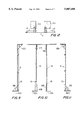
- FIGS. 1-4 show respectively a left elevational side, a front elevational, a right elevational side and top plan views of a rope pull safety device and industrial robot in accordance with the invention.
- FIG. 5 shows an elevational front view as in FIG. 2 but with the robot shown in position on a track.
- FIG. 6 shows an electrical schematic of a robot pull switch to be used in the invention.
- FIG. 7 shows a further electrical schematic representation of FIG. 6.
- FIG. 8 shows the invention of FIGS. 1-4 in position within a mini-environment and supported along a track as in FIG. 5.
- FIGS. 9-12 show respectively a left elevational side, a front elevational, a right elevational side and top plan views of a top bracket for a rope pull switch and industrial robot in accordance with the invention.
- FIGS. 13 and 14 show respectively left side elevational and front views of a left bracket for a left rope pull switch.
- FIGS. 15 and 16 show respectively left side elevational and front views of a right bracket for a right rope pull switch.
- FIGS. 1-4 show an industrial robot for use in a semiconductor wafer wet station with a rope pull safety device attached in accordance with the invention.
- the robot itself is conventional and preferably obtained from SubMicron Systems under the name GAMA ROBOT.
- the modification in accordance with the invention includes adding top and bottom brackets, a pull switch assembly and stainless steel TEFLONTM coated rope.
- FIG. 1 shows the left bottom bracket 2 for the left rope pull switch 12 while FIG. 3 shows the right bottom bracket 4 for the right rope pull switch 14.
- FIG. 4 shows the top bracket 6. Between the top bracket 6 and each of the left and right pull switches 12, 14 extends a stainless steel TeflonTM coated rope 8. The brackets are installed to an industrial robot 20 in the manner described below.
- Safety precautions Completely drain all process tanks at the work stations to remove chemicals. Ensure that all chemical fumes are evacuated. Put the robot in joystick mode, setting the end effector to the highest position allowed and setting the robot torso to a location at which there is complete access from the front of the mini-environment enclosure when the access panel and window of the enclosure are open simultaneously. Ensure that the industrial robot is electrically disabled.
- Installation of the left bottom bracket 2 is as follows. Locate lower vertical robot limit switch or sensor mounting plate 40 in reference to the robot torso. Remove the existing sensor plate fasteners and place the left bottom bracket 2 on top of the sensor mounting plate 40 and secure with fasteners. Match the sensor location with the mark made previously and arrange the bracket 2 parallel to the floor, i.e., horizontally level. Mount the rope pull switch 12 with its ring on the top position and provide a top label on it facing toward the center of the robot torso of the robot 20.
- Installation of the right bottom bracket 4 is as follows. Locate the lower flexible conduit mounting bracket 44. Remove its fasteners and place the right bottom bracket 4 on top of the flexible conduit mounting bracket 44 and install with fasteners. Mount the rope pull switch with its ring in the top position and with a label on it facing toward the center of the robot torso.
- Installation of the top bracket 6 is as follows: Locate the robot product detector arm mounting bracket 46. Conveniently secure the product detector arm to prevent it from dropping when removing existing fasteners. Place the base plate 18A of the right section 18 of the top bracket 6 between the robot torso top end and the product mounting bracket 46 and secure with fasteners. Preferably, the right section of the top bracket 46 has a four hole pattern with slots facing toward the mini-environment. Next, locate the top end robot torso left hole pattern 48. Attach the base plate 16A of the left section 16 of the top bracket 6 to the top end robot torso left hole pattern 48 with fasteners.
- Installation of the rope 8 is as follows. At the left side of the top end 10 of the rope 8, make a loop 10 (such as with a 1/2 inch inside diameter), insert the shrink tubing 22 (such as one inch length) and a sleeve, secure the loop 10 with a crimp tool and place the shrink tubing 22 on top of the sleeve and open rope end. Apply heat with a heat gun to encapsulate all exposed metal at the sleeve and rope end. Place the loop 10 around the top left bracket end hook 32. Ensure that the left pull switch 12 is mounted such that housing mounting slots have clearance above mounting screws. The clearance is required for further pull switch and rope pre-tensioning condition.
- the robot controller box is modified in accordance with the schematics of FIGS. 6 and 7.
- Fish wire through the existing robot flexible conduit. Use tight wraps to secure the wire with the lines that are going to a motor control box.
- check for continuity while manually actuating the pull switch via the rope Before final hookup of the rope pull circuitry to the terminal block inside the robot motor controller box, check for continuity while manually actuating the pull switch via the rope.
- the circuitry should be open to stop operation of the robot.
- no shutdown will occur since the rope displaced is within tolerable limits. Only reaching or exceeding those limits triggers shutdown.
- FIG. 6 is an electrical schematic of the robot pull switch such as a double pole throw switch.
- Also shown in the robot controller box 50 is 18 AWG wire 60 connecting terminals 62 of throw switch 56 and a contact location 64 for cable 66 leading to the left and right pull switches 54, 56.
- FIG. 7 shows a schematic diagram of FIG. 7 with a robot stop switch 52, a left pull switch 54, a right pull switch 56, all connected in series between a power supply 68 such as 24V-DC and a POS terminal such as in an electric tower 70.
- FIG. 8 shows the robot with mounting brackets and robot pull assembly within a mini-environment enclosure 90 having an access window 92 and an access panel 94. Between the access window 92 and the access panel 94 is an extra lip or edge 96, which is fastened to the mini-environment enclosure 90 by fasteners. Such an edge may be safely removed to allow the rope 8 (see FIGS. 1-4) to ride free close to a pinch section between the wall of the mini-environment enclosure and sections of the robot 20.
- Suitable rope pull switches are manufactured by EEControls, type ES51Z 10/1S and a suitable rope is a TEFLONTM coated 304 stainless steel manufactured by Reid Tool Supply Company, model no. CBL-375 with a 1/16 inch diameter wire coating and 0.084 inch outside diameter,
- the rope pull safety device functions to disable the robot when it encounters an obstruction, (as the joystick stop button does), during the horizontal left or right moves.
- the vertical extension bracket will be put in place and fixed to the robot torso top end section. This component will extend the height of the mini-environment access window. At the same time there is attached to bottom section of the Gama robot torso two mounting brackets to hold two rope pull CE rated safety switches, respectively.
- the safety device will require 1.75 LBS to actuate, giving maximum sensitivity with a horizontal rope displacement of 0.75", 2.00" before any contact with the robot torso, vertical section or any hard fixed pinch point.
- the rope pull interlock switches are Normally Close contacts, which are connected to the robot stop interlock circuit. Activation of the pull switch or any break in the circuit, (broken wire or loose connection), will cause the robot to stop.
- FIGS. 9-12 show the top rope pull bracket 6, with the left rope pull portion 16 and the right rope pull portion 18.
- Each has a respective base plate 16A, 16B that attaches to the robot torso and side angle plates 16B, 18B that extend at a 45 degree angle to help stabilize the bracket structure.
- FIGS. 13 and 14 show the left bottom bracket 2 with holes 72 and
- FIGS. 15 and 16 show the right bottom bracket 4 with holes 72.
- the top bracket could be divided into two separate left and right top mounting brackets so as to provide for a total of four brackets instead of three.
- the two mounting bottom brackets could be connected together, thereby providing for a single lower bracket that extends between the left and right sides of the robot, i.e., in the path of travel of the robot to the left or right direction as applicable.
- the rope may be any type of tensionable element, such a cable.
Landscapes
- Engineering & Computer Science (AREA)
- Mechanical Engineering (AREA)
- General Engineering & Computer Science (AREA)
- Robotics (AREA)
- Manipulator (AREA)
Abstract
Description
Claims (12)
Priority Applications (1)
| Application Number | Priority Date | Filing Date | Title |
|---|---|---|---|
| US08/851,668 US5807408A (en) | 1997-05-06 | 1997-05-06 | Industrial robot safety device that shuts down operation in reponse to variation in tension of a rope |
Applications Claiming Priority (1)
| Application Number | Priority Date | Filing Date | Title |
|---|---|---|---|
| US08/851,668 US5807408A (en) | 1997-05-06 | 1997-05-06 | Industrial robot safety device that shuts down operation in reponse to variation in tension of a rope |
Publications (1)
| Publication Number | Publication Date |
|---|---|
| US5807408A true US5807408A (en) | 1998-09-15 |
Family
ID=25311354
Family Applications (1)
| Application Number | Title | Priority Date | Filing Date |
|---|---|---|---|
| US08/851,668 Expired - Fee Related US5807408A (en) | 1997-05-06 | 1997-05-06 | Industrial robot safety device that shuts down operation in reponse to variation in tension of a rope |
Country Status (1)
| Country | Link |
|---|---|
| US (1) | US5807408A (en) |
Cited By (4)
| Publication number | Priority date | Publication date | Assignee | Title |
|---|---|---|---|---|
| US6346751B1 (en) | 2000-02-14 | 2002-02-12 | Ocim, S.R.L. | Safety tool mount for robotic apparatus |
| US20050177279A1 (en) * | 2004-02-10 | 2005-08-11 | Sig Doboy Inc. | Robot end effector detachment sensor |
| US20100101359A1 (en) * | 2007-01-29 | 2010-04-29 | Robert Bosch Gmbh | Device for displacing and positioning an object in space |
| US20150027862A1 (en) * | 2013-07-26 | 2015-01-29 | Seiko Epson Corporation | Robot and emergency stop method of robot |
Citations (3)
| Publication number | Priority date | Publication date | Assignee | Title |
|---|---|---|---|---|
| US4697979A (en) * | 1984-01-31 | 1987-10-06 | Fanuc Ltd. | Robot system safety method |
| US4795957A (en) * | 1987-09-03 | 1989-01-03 | Polaroid Corporation, Patent Department | Robot arm having motion-limiting tether |
| US5280622A (en) * | 1992-07-17 | 1994-01-18 | Mitsubishi Semiconductor America, Inc. | Combined light beam and ultrasonic transducer safety sensing system |
-
1997
- 1997-05-06 US US08/851,668 patent/US5807408A/en not_active Expired - Fee Related
Patent Citations (3)
| Publication number | Priority date | Publication date | Assignee | Title |
|---|---|---|---|---|
| US4697979A (en) * | 1984-01-31 | 1987-10-06 | Fanuc Ltd. | Robot system safety method |
| US4795957A (en) * | 1987-09-03 | 1989-01-03 | Polaroid Corporation, Patent Department | Robot arm having motion-limiting tether |
| US5280622A (en) * | 1992-07-17 | 1994-01-18 | Mitsubishi Semiconductor America, Inc. | Combined light beam and ultrasonic transducer safety sensing system |
Cited By (7)
| Publication number | Priority date | Publication date | Assignee | Title |
|---|---|---|---|---|
| US6346751B1 (en) | 2000-02-14 | 2002-02-12 | Ocim, S.R.L. | Safety tool mount for robotic apparatus |
| US20050177279A1 (en) * | 2004-02-10 | 2005-08-11 | Sig Doboy Inc. | Robot end effector detachment sensor |
| US7395136B2 (en) | 2004-02-10 | 2008-07-01 | Sig Doboy Inc. | Robot end effector detachment sensor |
| US20100101359A1 (en) * | 2007-01-29 | 2010-04-29 | Robert Bosch Gmbh | Device for displacing and positioning an object in space |
| US8181551B2 (en) * | 2007-01-29 | 2012-05-22 | Robert Bosch Gmbh | Device for displacing and positioning an object in space and which can detect the decoupling of a joint of a parallelogram rod assembly |
| US20150027862A1 (en) * | 2013-07-26 | 2015-01-29 | Seiko Epson Corporation | Robot and emergency stop method of robot |
| US9548168B2 (en) * | 2013-07-26 | 2017-01-17 | Seiko Epson Corporation | Robot and emergency stop method of robot |
Similar Documents
| Publication | Publication Date | Title |
|---|---|---|
| KR102363430B1 (en) | Hanger Equipment For Underground Distribution Line | |
| WO2012119194A1 (en) | Solar cell installation. cut-out switch and method | |
| KR101995327B1 (en) | Short circuit reinforcement unit of electric power supply cable | |
| US5807408A (en) | Industrial robot safety device that shuts down operation in reponse to variation in tension of a rope | |
| US3904843A (en) | Self-switching retracting reel | |
| KR102326004B1 (en) | Building trays that can protect electric cables | |
| KR102624745B1 (en) | Electrical Power Receiving Equipment | |
| KR101848089B1 (en) | Distribution line protection panel for underground line | |
| KR102656856B1 (en) | Power distribution management system linked to artificial intelligence | |
| KR102173381B1 (en) | Terminal box for apartment house | |
| JPH0657586B2 (en) | Elevator device | |
| KR20030092115A (en) | Elevator control device | |
| KR101181934B1 (en) | Alarming appratus preventing from stealing earth cable | |
| US20170356214A1 (en) | Equipment protection system and protection device thereof | |
| US11679956B2 (en) | Elevator system including a derailment contact | |
| CA2722298A1 (en) | Thermal insulation detector | |
| KR102449100B1 (en) | fire extinguisher | |
| KR102596782B1 (en) | Structure of the protective cover for the incoming wire with insulation and non-combustible functions of the indoor electrical switchgear of the building | |
| US6625934B1 (en) | Method for monitoring environmental conditions in restricted spaces | |
| CN114887262A (en) | Automatic fire early warning and fire extinguishing system for photovoltaic building roof | |
| KR102596781B1 (en) | A protective cover device for incoming lines with a ventilation function for indoor electrical switchboards of buildings | |
| WO2000074190A1 (en) | Decorative frame | |
| KR102451129B1 (en) | An underground distribution line connection type support device capable of detecting abnormalities | |
| US3896906A (en) | Seismic sensing apparatus | |
| KR102505567B1 (en) | Method of providing an electric shock accident prevention system for workers for processing and distribution |
Legal Events
| Date | Code | Title | Description |
|---|---|---|---|
| AS | Assignment |
Owner name: SUBMICRON SYSTEMS, INC., PENNSYLVANIA Free format text: ASSIGNMENT OF ASSIGNORS INTEREST;ASSIGNOR:RUIZ, CARLOS M.;REEL/FRAME:008544/0626 Effective date: 19970428 |
|
| AS | Assignment |
Owner name: GREYROCK BUSINESS CREDIT, A DIVISION OF NATIONSCRE Free format text: SECURITY INTEREST;ASSIGNOR:SUBMICRON SYSTEMS, INC.;REEL/FRAME:008886/0373 Effective date: 19971125 |
|
| AS | Assignment |
Owner name: WILMINGTON TRUST COMPANY, NEW YORK Free format text: SECURITY INTEREST;ASSIGNOR:SUBMICRON SYSTEMS CORPORATION;REEL/FRAME:010078/0687 Effective date: 19990701 |
|
| AS | Assignment |
Owner name: SUBMICRON SYSTEMS CORPORATION, PENNSYLVANIA Free format text: RELEASE BY SECURED PARTY;ASSIGNOR:WILMINGTON TRUST COMPANY;REEL/FRAME:010321/0985 Effective date: 19991014 |
|
| AS | Assignment |
Owner name: GREYROCK CAPITAL, A DIVISION OF BANC OF AMERICA CO Free format text: SECURITY INTEREST;ASSIGNOR:AKRION LLC;REEL/FRAME:010602/0246 Effective date: 20000114 |
|
| AS | Assignment |
Owner name: AKRION LLC, PENNSYLVANIA Free format text: ASSIGNMENT OF ASSIGNORS INTEREST;ASSIGNOR:SUBMICRON SYSTEMS INC.;REEL/FRAME:011314/0462 Effective date: 19991015 |
|
| AS | Assignment |
Owner name: GENERAL ELECTRIC CAPITAL CORPORATION, CONNECTICUT Free format text: SECURITY INTEREST;ASSIGNOR:AKRION LLC;REEL/FRAME:011497/0675 Effective date: 20001121 |
|
| REMI | Maintenance fee reminder mailed | ||
| FPAY | Fee payment |
Year of fee payment: 4 |
|
| SULP | Surcharge for late payment | ||
| AS | Assignment |
Owner name: SILICON VALLEY BANK DBA SILICON VALLEY EAST, CALIF Free format text: SECURITY INTEREST;ASSIGNOR:AKRION LLC;REEL/FRAME:013758/0519 Effective date: 20030623 |
|
| AS | Assignment |
Owner name: AKRION LLC, PENNSYLVANIA Free format text: RELEASE OF SECURITY INTEREST AND REASSIGNMENT;ASSIGNOR:GENERAL ELECTRIC CAPITAL CORPORATION;REEL/FRAME:014215/0618 Effective date: 20030623 |
|
| AS | Assignment |
Owner name: ORIX VENTURE FINANCE LLC, NEW YORK Free format text: SECURITY INTEREST;ASSIGNOR:AKRION LLC;REEL/FRAME:015348/0313 Effective date: 20040428 |
|
| AS | Assignment |
Owner name: AKRION, INC., PENNSYLVANIA Free format text: MERGER;ASSIGNOR:AKRION, LLC;REEL/FRAME:017015/0695 Effective date: 20040826 |
|
| AS | Assignment |
Owner name: AKRION TECHNOLOGIES, INC., DELAWARE Free format text: ASSIGNMENT OF ASSIGNORS INTEREST;ASSIGNOR:AKRION, INC.;REEL/FRAME:017065/0116 Effective date: 20050125 |
|
| REMI | Maintenance fee reminder mailed | ||
| AS | Assignment |
Owner name: AKRION INC., PENNSYLVANIA Free format text: RELEASE OF SECURITY INTEREST IN PATENTS;ASSIGNOR:ORIX VENTURE FINANCE LLC;REEL/FRAME:018160/0627 Effective date: 20060705 Owner name: BHC INTERIM FUNDING II, L.P., NEW YORK Free format text: SECURITY AGREEMENT;ASSIGNOR:AKRION TECHNOLOGIES, INC.;REEL/FRAME:018160/0597 Effective date: 20060705 Owner name: GOLDFINGER TECHNOLOGIES, LLC, PENNSYLVANIA Free format text: RELEASE OF SECURITY INTEREST IN PATENTS;ASSIGNOR:ORIX VENTURE FINANCE LLC;REEL/FRAME:018160/0627 Effective date: 20060705 |
|
| LAPS | Lapse for failure to pay maintenance fees | ||
| STCH | Information on status: patent discontinuation |
Free format text: PATENT EXPIRED DUE TO NONPAYMENT OF MAINTENANCE FEES UNDER 37 CFR 1.362 |
|
| FP | Expired due to failure to pay maintenance fee |
Effective date: 20060915 |
|
| AS | Assignment |
Owner name: SUNRISE CAPITAL PARTNERS, L.P., NEW YORK Free format text: SECURITY AGREEMENT;ASSIGNOR:AKRION TECHNOLOGIES, INC.;REEL/FRAME:021462/0283 Effective date: 20080812 |
|
| AS | Assignment |
Owner name: WAFER HOLDINGS, INC., PENNSYLVANIA Free format text: ASSIGNMENT OF ASSIGNORS INTEREST;ASSIGNORS:PNC BANK, NATIONAL ASSOCIATION;BHC INTERIM FUNDING II, L.P.;AKRION, INC.;AND OTHERS;REEL/FRAME:021658/0928 Effective date: 20080926 |
|
| AS | Assignment |
Owner name: BHC INTERIM FUNDING II, L.P., NEW YORK Free format text: SECURITY AGREEMENT;ASSIGNOR:WAFER HOLDINGS, INC.;REEL/FRAME:021731/0718 Effective date: 20080926 Owner name: PNC BANK, NATIONAL ASSOCIATION, PENNSYLVANIA Free format text: SECURITY AGREEMENT;ASSIGNOR:WAFER HOLDINGS, INC.;REEL/FRAME:021744/0209 Effective date: 20080926 Owner name: PNC BANK, NATIONAL ASSOCIATION, PENNSYLVANIA Free format text: SECURITY AGREEMENT;ASSIGNOR:WAFER HOLDINGS, INC.;REEL/FRAME:021731/0608 Effective date: 20080926 |
|
| AS | Assignment |
Owner name: AKRION SYSTEMS LLC, PENNSYLVANIA Free format text: ASSIGNMENT OF ASSIGNORS INTEREST;ASSIGNORS:WAFER HOLDINGS, INC.;AKRION TECHNOLOGIES, INC.;REEL/FRAME:022824/0970 Effective date: 20090616 |
|
| AS | Assignment |
Owner name: PNC BANK, NATIONAL ASSOCIATION, PENNSYLVANIA Free format text: SECURITY AGREEMENT;ASSIGNOR:AKRION SYSTEMS, LLC;REEL/FRAME:022973/0811 Effective date: 20090618 |
|
| AS | Assignment |
Owner name: BHC INTERIM FUNDING II, L.P., NEW YORK Free format text: SECURITY AGREEMENT;ASSIGNOR:AKRION SYSTEMS LLC;REEL/FRAME:023220/0423 Effective date: 20090616 |
|
| AS | Assignment |
Owner name: WAFER HOLDINGS, INC., PENNSYLVANIA Free format text: TERMINATION AND RELEASE OF TRADEMARK AND PATENT SECURITY AGREEMENT RECORDED AT REEL 21744/FRAME 0209 AND REEL 21731/FRAME 0608;ASSIGNOR:PNC BANK, NATIONAL ASSOCIATION;REEL/FRAME:045097/0070 Effective date: 20180116 Owner name: AKRION SYSTEMS LLC, PENNSYLVANIA Free format text: TERMINATION AND RELEASE OF TRADEMARK AND PATENT SECURITY AGREEMENT RECORDED AT REEL 23220/FRAME 0423;ASSIGNOR:BHC INTERIM FUNDING II, L.P.;REEL/FRAME:045102/0189 Effective date: 20180116 Owner name: AKRION SYSTEMS LLC, PENNSYLVANIA Free format text: TERMINATION AND RELEASE OF TRADEMARK AND PATENT SECURITY AGREEMENT RECORDED AT REEL 22973/FRAME 0811;ASSIGNOR:PNC BANK, NATIONAL ASSOCIATION;REEL/FRAME:045102/0288 Effective date: 20180116 Owner name: WAFER HOLDINGS, INC., PENNSYLVANIA Free format text: TERMINATION AND RELEASE OF TRADEMARK AND PATENT SECURITY AGREEMENT RECORDED AT REEL 021731/FRAME 0718;ASSIGNOR:BHC INTERIM FUNDING II, L.P.;REEL/FRAME:045103/0624 Effective date: 20180116 |