US580733A - Flbisch - Google Patents
Flbisch Download PDFInfo
- Publication number
- US580733A US580733A US580733DA US580733A US 580733 A US580733 A US 580733A US 580733D A US580733D A US 580733DA US 580733 A US580733 A US 580733A
- Authority
- US
- United States
- Prior art keywords
- stripping
- drum
- teeth
- teazels
- clothing
- Prior art date
- Legal status (The legal status is an assumption and is not a legal conclusion. Google has not performed a legal analysis and makes no representation as to the accuracy of the status listed.)
- Expired - Lifetime
Links
- 238000004140 cleaning Methods 0.000 description 7
- 230000002093 peripheral effect Effects 0.000 description 2
- 229940000425 combination drug Drugs 0.000 description 1
- 238000010276 construction Methods 0.000 description 1
- 238000009432 framing Methods 0.000 description 1
Images
Classifications
-
- D—TEXTILES; PAPER
- D06—TREATMENT OF TEXTILES OR THE LIKE; LAUNDERING; FLEXIBLE MATERIALS NOT OTHERWISE PROVIDED FOR
- D06C—FINISHING, DRESSING, TENTERING OR STRETCHING TEXTILE FABRICS
- D06C11/00—Teasing, napping or otherwise roughening or raising pile of textile fabrics
Definitions
- Tn sums mms cm moroni-no. wAsxmoToN, n. c.
- My invention relates to apparatus for cleaning napping-machines; and it has-for its object to strip the nuff ont of the teazels in such a manner that the natural roughness of the teazels shall not be injuriously affected or the teeth of the card-clothing or artiicial teazels be bent or deformed thereby.
- a stripping apparatus comprises a drum adapted to revolve with a peripheral velocity equal or corresponding to that of the teazels to be cleaned and carrying a series of bars which are provided With stripping-clothing and are suitably guided so that they can be moved longitudinally as regards the drum by means of curved guides or cams fixed to the framing at the ends of the drum and be afterwardquickly brought back to their normal positions by means of springs that have been strained by the previous longitudinal Inovement of said bars, the arrangement being such that the stripping-teeth of the bars are caused to pass through the spaces between the teeth of the teazels, and as they are rearwardly inclined they will thereby throw out the fluff that has been combed out bythe napping-teeth.
- the apparatus as arranged for stripping a napping-machine fitted with artificial teazels arranged obliquely to one another and at a slight inclination to the axis of the main napping-drum.
- the clothing of the stripping-drum should have a velocity corresponding to the velocity of the articial teazels, in order that the several teeth of the card-clothing of the stripping-drum shall pass through the spaces between the teeth of the artificial teazels, and the direction of rotation of the stripping-drum must be such that the paths described by a Serial No. 599,904. (No model.)
- row of teeth of the stripping-drum and the artificial teazels during their rotation shall be alike or correspond.
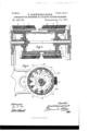
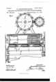
- Figure 1 shows in longitudinal vertical section, taken in different planes at opposite ends, a stripping apparatus constructed according to this invention.
- Fig. 2 is a vertical cross-section of the stripping apparatus.
- Fig. 3 is a vertical oross-section showing the stripping apparatus combined with a napping-machine, and
- Fig. 4 isapart horizontal section thereof.
- ct is the stripping-clothing, made with long teeth and fixed on the bars Z2, which form the periphery of the stripping-drum h.
- These bars are each so mounted on the strippingdrum that as the drum revolves they are moved by a cam d automatically and longitudinally to the teazels to be cleaned and against the action of a spring o, which when a bar b is released by the said cam d causes the stripping-clothing a to move back automatically in such a manner that the rearwardly-inclined stripping-teeth enter in between the card-teeth of the artificial teazels e and strip the fluff from out thereof without in]l uriously affecting the teazels.
- the artificial teazels of the napping-machine may,as in the examples shown,be driven by means of toothed wheels or pinions g, g', and g2 from intermediate shafts g3, which are driven in a suitable manner from the main shaft g l
- each shaft g3 is mounted in the end walls of the napping-drum upon which the teazels e are mounted and is driven by a toothed wheel g4, that gears with a xed internally-toothed ring g5, round which the wheel g4 is carried, and thereby rotated by the motion of the said drum.
- Every two successive rows of artificial teazels e e2, Fig. 3 are arranged obliquely to each other on the periphery of the napping-drum.
- the stripping-drum h is provided with two series of stripper-bars- 95 viz., b b'-arranged alternately around the drum, the teeth of the card-clothing a on one fseries of bars inclining backwardly in an 0pposite direction to that of the clothing a on the other series of bars.
- Each bar b b' is Ioo teazels e.
- a ,pulley on the Vshaft 'L' of .the stripping-.drum may be driven from a pulley on the shaft g of :thenappingg
- the rotary vmotion ⁇ causes r.thecarriages or slide-,bars Z, and with them Vvthe -barsfh band stripping-clothing cac'
- each cam d has an ,abruptly-,dccliningedge fm, .so that when theproj-ection Z.of a'carriage or slide-bar Z arrives thereat .the corresponding spring c or c willfcause ⁇ the carriage or -slide Z, and consequently, .al-so, the corresponding bar Z9, to mnve'iback suddenly, and the stripping-.clothingfaxthereof to pass through the spaces between the teethof the corresponding teazel e.
- the teeth of ⁇ the stripping-clothing a have abackward inclination fthe spaces between the teeth of the teazels e will be cleaned Without the extracted uff entering the-said stripping-clothing.
- the bars b b' are soarrranged that the clothing@ of one barviz.,.h-.c leans when moving inone directionviz.,.fro1n left to r-ight in Fig. l-while the clothing a of the next following bar Z9 cleans when moving in the reverse direction-viz., from right to left in Fig. 1.
- cams dd are provided at both ends of the drum h and that there are two sets fofsprings-viz., c c-acting in opposite directions, so that the-clothing a of the bars b will traverse the spaces between the teeth cleaned lwithout damage to their teeth and without the fluff being taken vupbyvthe stripping-teeth of the cleaning apparatus.
- stripping 4apparatus comprising a rotaryd-rum carrying a number of longitudinally-movable bars b b provided With stripping-clothing a a arranged toact alternately in opposite directions and the peripheral velocity of which corresponds to -that of :the .teazels to loe-stripped or cleaned, and ymeans for moving-said bars longitudinally,substantiall y as described. ⁇
Landscapes
- Engineering & Computer Science (AREA)
- Textile Engineering (AREA)
- Detergent Compositions (AREA)
- Preliminary Treatment Of Fibers (AREA)
Description
V (No Model.) 2 Sheets-Sheet 1.
E. SQBWBINEFLBISGH. `APPARATTIE FOR STRIPIING 0R CLEANING NAPPING MACHINES.
No. 580,733. 3 Patented Apr. 13, 1897.
Tn: sums mms cm moroni-no. wAsxmoToN, n. c.
(No Model.) 2 Sheets-Sheet 2.
E. SGHWEIBIEFLEISGEI'. APPARATUS PON STRIPPING 0N CLEANING NAPPING MACHINES.
A zwwwwykw MM wfwci@ UNITED STATES l PATENT OFFICE.
ERNST SCHVVEINEELEISCH, OF MHLHAUSEN, GERMANY.
APPARATUS FOR STRIPPING R CLEANING NAPPlNG-MACHINES.
SPECIFICATION forming part of Letters Patent No. 580,733, dated April 13, 1897.
Application led J'uly 20, 1896.
T0 @ZZ whom it may concern,.-
Be it known that I, ERNST SCHWETNE- FLEISCH, fabric-finisher, a subject of the King of Prussia, German Emperor, residing at Mhlhausen, in the Kingdom of Prussia and German Empire, have invented new and useful Improvements in Apparatus for Stripping or Cleaning Napping-Machines, of which the following is a specification.
My invention relates to apparatus for cleaning napping-machines; and it has-for its object to strip the nuff ont of the teazels in such a manner that the natural roughness of the teazels shall not be injuriously affected or the teeth of the card-clothing or artiicial teazels be bent or deformed thereby. A stripping apparatus according to this invention comprises a drum adapted to revolve with a peripheral velocity equal or corresponding to that of the teazels to be cleaned and carrying a series of bars which are provided With stripping-clothing and are suitably guided so that they can be moved longitudinally as regards the drum by means of curved guides or cams fixed to the framing at the ends of the drum and be afterwardquickly brought back to their normal positions by means of springs that have been strained by the previous longitudinal Inovement of said bars, the arrangement being such that the stripping-teeth of the bars are caused to pass through the spaces between the teeth of the teazels, and as they are rearwardly inclined they will thereby throw out the fluff that has been combed out bythe napping-teeth.
I will describe the apparatus as arranged for stripping a napping-machine fitted with artificial teazels arranged obliquely to one another and at a slight inclination to the axis of the main napping-drum. For completely stripping such a machine it is necessarythat the clothing of the stripping-drum should have a velocity corresponding to the velocity of the articial teazels, in order that the several teeth of the card-clothing of the stripping-drum shall pass through the spaces between the teeth of the artificial teazels, and the direction of rotation of the stripping-drum must be such that the paths described by a Serial No. 599,904. (No model.)
row of teeth of the stripping-drum and the artificial teazels during their rotation shall be alike or correspond.
In the accompanying drawings, Figure 1 shows in longitudinal vertical section, taken in different planes at opposite ends, a stripping apparatus constructed according to this invention. Fig. 2 is a vertical cross-section of the stripping apparatus. Fig. 3 is a vertical oross-section showing the stripping apparatus combined with a napping-machine, and Fig. 4 isapart horizontal section thereof.
ct is the stripping-clothing, made with long teeth and fixed on the bars Z2, which form the periphery of the stripping-drum h. These bars are each so mounted on the strippingdrum that as the drum revolves they are moved by a cam d automatically and longitudinally to the teazels to be cleaned and against the action of a spring o, which when a bar b is released by the said cam d causes the stripping-clothing a to move back automatically in such a manner that the rearwardly-inclined stripping-teeth enter in between the card-teeth of the artificial teazels e and strip the fluff from out thereof without in]l uriously affecting the teazels.
The artificial teazels of the napping-machine may,as in the examples shown,be driven by means of toothed wheels or pinions g, g', and g2 from intermediate shafts g3, which are driven in a suitable manner from the main shaft g l In the example shown each shaft g3 is mounted in the end walls of the napping-drum upon which the teazels e are mounted and is driven by a toothed wheel g4, that gears with a xed internally-toothed ring g5, round which the wheel g4 is carried, and thereby rotated by the motion of the said drum. Every two successive rows of artificial teazels e e2, Fig. 3, are arranged obliquely to each other on the periphery of the napping-drum. l
[n the example shown the stripping-drum h is provided with two series of stripper-bars- 95 viz., b b'-arranged alternately around the drum, the teeth of the card-clothing a on one fseries of bars inclining backwardly in an 0pposite direction to that of the clothing a on the other series of bars. Each bar b b' is Ioo teazels e.
xed upon a carriage or slide Z, which is in the form of a bar, 4arrangeil to slidefen'dwise inza guideway in the drum h and connected to one end of a spring c or c', located within the stripping-drum h, and the other end of which ina circular manner at the ends of said drum. This drum his rotated in the opposite direction to the-napping-drurn in such a manner that the circumferentialvelocity of the-stripping-clothing a a is the same as that of the vdrum `through afcrossed belt oriotherwise.
For fth-is purpose a ,pulley on the Vshaft 'L' of .the stripping-.drum ,may be driven from a pulley on the shaft g of :thenappingg By 'the construction described when the, stripping-:drum h rotates A,the rotary vmotion` causes r.thecarriages or slide-,bars Z, and with them Vvthe -barsfh band stripping-clothing cac',
to -move ,longitudinally on the drum, these parts .beingdrawn outward from the drum in onesdirectienforthe other'by'the cams d against theactionof .the-springsfc. Each cam dhas an ,abruptly-,dccliningedge fm, .so that when theproj-ection Z.of a'carriage or slide-bar Z arrives thereat .the corresponding spring c or c willfcause `the carriage or -slide Z, and consequently, .al-so, the corresponding bar Z9, to mnve'iback suddenly, and the stripping-.clothingfaxthereof to pass through the spaces between the teethof the corresponding teazel e. ,As the teeth of `the stripping-clothing a have abackward inclination fthe spaces between the teeth of the teazels e will be cleaned Without the extracted uff entering the-said stripping-clothing. i
As the teeth of :the stripper-clothing a are inclined in an opposite direction to the lteeth of the stripping-clothing-a the bars b b' are soarrranged that the clothing@ of one barviz.,.h-.c leans when moving inone directionviz.,.fro1n left to r-ight in Fig. l-while the clothing a of the next following bar Z9 cleans when moving in the reverse direction-viz., from right to left in Fig. 1. It is for this reason .that cams dd are provided at both ends of the drum h and that there are two sets fofsprings-viz., c c-acting in opposite directions, so that the-clothing a of the bars b will traverse the spaces between the teeth cleaned lwithout damage to their teeth and without the fluff being taken vupbyvthe stripping-teeth of the cleaning apparatus.
'I-Iavi-ngnowparticularly described and ascertained the nature of the said invention and in what manner thesame is to beperformed, I declare that what Lclaim isl. In apparatus for rstripping for cleaning napping-machines, the combi-nation of a rotarydruln carrying a numbenof Alongitudinally-movable bar-s that are provided -wit'h stripper clothing havin-g inclined teeth, means for guidingsaid -bars,so that vthey can be moved longitudinallyas regards thedrum, stationarycams to causegaimovement ofsaid barsin one directiomand lsprings which, when the-said bars are released, lserve to rbring them quickly back again i-n such ,amannerthat the teeth of the-strippingclothinglon each .bar in succession are caused to :pass through the spaces between vthe teeth of theteazels of the napping-machine and ythereby throw 'out the 'lu held by such teeth, substantially as ldescribed.
2. rPhe -combination with a napping-machine provided With teazels arranged around the napping-drum in longitudinal Vrows each adjacent two of which are inclined vto voneanother, of stripping 4apparatus comprising a rotaryd-rum carrying a number of longitudinally-movable bars b b provided With stripping-clothing a a arranged toact alternately in opposite directions and the peripheral velocity of which corresponds to -that of :the .teazels to loe-stripped or cleaned, and ymeans for moving-said bars longitudinally,substantiall y as described.`
In testimony whereof I have hereunto set my hand in presence of two subscribing witnesses.
ERNST SCHWEINEFLEISCH.
Witnesses:
I. TEICHMANN, FANIE MOORE.
IOO
Publications (1)
| Publication Number | Publication Date |
|---|---|
| US580733A true US580733A (en) | 1897-04-13 |
Family
ID=2649411
Family Applications (1)
| Application Number | Title | Priority Date | Filing Date |
|---|---|---|---|
| US580733D Expired - Lifetime US580733A (en) | Flbisch |
Country Status (1)
| Country | Link |
|---|---|
| US (1) | US580733A (en) |
-
0
- US US580733D patent/US580733A/en not_active Expired - Lifetime
Similar Documents
| Publication | Publication Date | Title |
|---|---|---|
| US2317747A (en) | Yarn processing apparatus | |
| US2302508A (en) | Apparatus for stretching filiform materials | |
| US3311500A (en) | Continuous feed bottle system for bottle washing machine | |
| US2789564A (en) | Tobacco leaf deveining machine | |
| US652843A (en) | Napping-machine. | |
| US329356A (en) | bradshaw | |
| US1566611A (en) | Fruit-cleaning machine | |
| US1476032A (en) | Apparatus for defiberizing wood | |
| US2535991A (en) | Circular, independent needle, knitting machine | |
| US222812A (en) | Improvement in mechanisms for stripping the top-flats of carding-machines | |
| US2372543A (en) | Stripping roll for long fiber feeders | |
| US1900808A (en) | Webxe grimme | |
| US1407184A (en) | Apparatus for making wire sieves or floors | |
| US2313791A (en) | Deseeding and cleaning machine | |
| US1284905A (en) | Wire-weaving machine. | |
| EP1469115A2 (en) | Apparatus for surface treatment of fabrics | |
| US363329A (en) | gbant | |
| US1131545A (en) | Machine for delinting cotton-seed. | |
| US1041742A (en) | Wire-fence machine. | |
| SU887124A1 (en) | Apparatus for merging several streams of parts into one stream | |
| US613398A (en) | Shifting mechanism for weaving-machines | |
| US938224A (en) | Cotton-gin. | |
| US1343076A (en) | Machine for covering wire with fibrous material | |
| US2332783A (en) | Gin saw cleaner | |
| US577602A (en) | Nicolas henry grosselin |