US5791532A - Process for reversing and end-shaping inflatable bodies - Google Patents
Process for reversing and end-shaping inflatable bodies Download PDFInfo
- Publication number
- US5791532A US5791532A US08/809,279 US80927997A US5791532A US 5791532 A US5791532 A US 5791532A US 80927997 A US80927997 A US 80927997A US 5791532 A US5791532 A US 5791532A
- Authority
- US
- United States
- Prior art keywords
- die
- reversing
- airbag
- reversing pipe
- pipe
- Prior art date
- Legal status (The legal status is an assumption and is not a legal conclusion. Google has not performed a legal analysis and makes no representation as to the accuracy of the status listed.)
- Expired - Fee Related
Links
Images


Classifications
-
- D—TEXTILES; PAPER
- D06—TREATMENT OF TEXTILES OR THE LIKE; LAUNDERING; FLEXIBLE MATERIALS NOT OTHERWISE PROVIDED FOR
- D06G—MECHANICAL OR PRESSURE CLEANING OF CARPETS, RUGS, SACKS, HIDES, OR OTHER SKIN OR TEXTILE ARTICLES OR FABRICS; TURNING INSIDE-OUT FLEXIBLE TUBULAR OR OTHER HOLLOW ARTICLES
- D06G3/00—Turning inside-out flexible tubular or other hollow articles
- D06G3/02—Turning inside-out flexible tubular or other hollow articles by mechanical means
-
- D—TEXTILES; PAPER
- D06—TREATMENT OF TEXTILES OR THE LIKE; LAUNDERING; FLEXIBLE MATERIALS NOT OTHERWISE PROVIDED FOR
- D06G—MECHANICAL OR PRESSURE CLEANING OF CARPETS, RUGS, SACKS, HIDES, OR OTHER SKIN OR TEXTILE ARTICLES OR FABRICS; TURNING INSIDE-OUT FLEXIBLE TUBULAR OR OTHER HOLLOW ARTICLES
- D06G3/00—Turning inside-out flexible tubular or other hollow articles
- D06G3/04—Turning inside-out flexible tubular or other hollow articles pneumatically
Definitions
- the invention relates to a process for reversing and finally shaping inflatable bodies consisting of fabric(s) with or without coating, in particular airbags, using a suitable device.
- the object of the present invention is to make available an economical process for the reversing of inflatable bodies, in particular of airbags, by means of a device that is particularly suitable for such a process.
- a reversing pipe receiving the body or airbag
- a die provided with a compressed-air connection and with a blow-out hole, whereby the downwardly driving die pushes the body or airbag completely into the reversing pipe while simultaneously reversing the body or airbag;
- a collecting device in which the body or airbag is finally shaped after it has been driven out of the reversing die by a blast of compressed air through the die so as to inflate and unfold it in the reversed condition.
- the compressed-air connection is located in the top part, particularly directly on the circumference of the die;
- a reversing head is arranged in the lower part, namely directly at the end of the die, said head being fitted with one or a plurality of blow-out openings, whereby the compressed-air connection is connected with the one or more blow-out opening(s) of the reversing head via an air duct contained in the die. Furthermore, when the reversing pipe is in the closed condition, the reversing head projects into the collecting device;
- the die has a sealing element, in particular a sealing plate made of metal and/or elastomeric material.
- the reversing pipe On its top edge, the reversing pipe is fitted with a sliding, ball or roller ring, such a ring being designed with respect to shape, material and surface in such a way that only minimal frictional forces are directed against the reversing process;
- the reversing pipe In the zone of transition between the end of the reversing pipe and the collecting device, the reversing pipe is designed in a way such that the final shaping process of the body or airbag is met by only minor resistance.
- each holding arm is, in this connection, usefully arranged above the sealing element or sealing plate, i.e., the sealing element or sealing plate is here an integrated component of the holding arm. It is particularly advantageous in connection with this overall arrangement principle if the reversing pipe is, as the body or airbag is being pushed in, driven downwardly by means of a drive at half the speed of the die.
- a collecting device is used, such device limiting the discharge of the body or airbag downwardly by means of a horizontal bottom for the purpose of obtaining as flat a final shaping as possible in the radial direction. Also, it is an advantage if the collecting device is alternatively designed in the form of a transporting device for removing the reversed and finally shaped body or airbag.
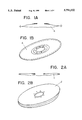
- FIG. 1A shows a sectional representation of an airbag immediately following its manufacture
- FIG. 1B shows a three-dimensional representation of the airbag according to FIG. 1A;
- FIG. 2A shows a sectional representation of a reversed and finally shaped airbag
- FIG. 2B shows a three-dimensional representation of an airbag according to FIG. 2A
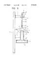
- FIG. 3 shows a device with the die extended
- FIG. 4 shows a device in connection with which the die penetrates the reversing pipe while the airbag is simultaneously received in the reversing pipe;
- FIG. 5 shows a device with the reversing pipe in the closed condition
- FIG. 6 shows a device with the reversing pipe in the closed condition as the reversed airbag is being driven out and simultaneous impacting the collecting device
- FIG. 7 shows a device with the airbag in the reversed and finally shaped condition.
- a Airbag (immediately after its manufacture)
- the device comprises a guide rail 1, which is fitted with two horizontally extending holding arms 1' and 1", whereby said holding arms are vertically displaceable within the guide rail by means of a drive.
- the die 4 is fitted with a sealing element 6 (here a sealing plate). Now, directly above said sealing plate, the die is connected with the holding arm 1' in a fixed way.
- a compressed-air connection 5 is located at the head 4' of the die, whereas the die end 4" is fitted with a reversing head 8, the latter in turn being provided with one or a plurality of blow-out opening(s) 5", whereby the compressed-air connection is connected with the blow-out opening(s) of the reversing head via an air duct 5' contained in the die.
- the reversing pipe 2 itself is connected in a fixed way with the holding arm 1" in its center zone. At its top edge 2', the reversing pipe 2 is fitted with a sliding, ball or roller ring 7, such a ring being designed with respect to its shape, material and surface in a way such that only low frictional forces are directed against the reversing process. Furthermore, in the transition zone 2" between the end of the reversing pipe and the collecting device 3, the reversing pipe is designed in a way such that the final shaping process of the airbag B (FIG. 6) into the condition C (FIGS. 2A, 2B, 7) is opposed by only minor resistance.
- the collecting device itself is downwardly limited by means of a horizontal bottom 3' for the purpose of obtaining as flat a final shaping of the airbag C as possible in the radial direction.
- the airbag A (FIGS. 1A, 1B), with the opening placed over the reversing pipe 2, is pushed into the reversing pipe 2 by the downwardly driving die 4 with the reversing head 8 (FIG. 4).
- the reversing pipe is moving downwardly (in the direction of the arrow according to FIG. 4) by means of a drive with half the speed of the die. Drawing of the airbag into the reversing pipe is facilitated in this way and the formation of sharp folds is prevented.
- This is supported by the sliding, ball, or roller ring mounted on the top edge of the reversing pipe, such ring being optimized with respect to shape and material.
- the die 4 moves relative to the reversing pipe 2 until the entire airbag B is present in the reversing pipe in the already reversed condition.
- the sealing plate 6 seals the reversing pipe against the top side.
- the reversing head 8 projects into the collecting device 3.
- a strong blast of air (via the compressed-air connection 5) through the air duct 5' of the die 4 and through the blow-out openings 5" of the reversing head 8 drives the airbag B out of the reversing pipe.
- the airbag then impacts the horizontal bottom 3' of the collecting device 3, inflating and unfolding of the airbag takes place.
- FIG. 7 shows the reversed and finally shaped airbag C, which is then removed from the collecting device 3.
- the die 4 now moved upwardly (in the direction of the arrow) at twice the speed of the reversing pipe 2, namely as the reversing pipe opens (starting condition according to FIG. 3).
Landscapes
- Engineering & Computer Science (AREA)
- Mechanical Engineering (AREA)
- Textile Engineering (AREA)
- Treatment Of Fiber Materials (AREA)
- Air Bags (AREA)
- Toys (AREA)
Abstract
Description
Claims (28)
Applications Claiming Priority (3)
| Application Number | Priority Date | Filing Date | Title |
|---|---|---|---|
| DE4443724 | 1994-12-09 | ||
| DE4443724.2 | 1994-12-09 | ||
| PCT/DE1995/001638 WO1996017993A1 (en) | 1994-12-09 | 1995-11-23 | Process for reversing and end shaping inflatable bodies |
Publications (1)
| Publication Number | Publication Date |
|---|---|
| US5791532A true US5791532A (en) | 1998-08-11 |
Family
ID=6535285
Family Applications (1)
| Application Number | Title | Priority Date | Filing Date |
|---|---|---|---|
| US08/809,279 Expired - Fee Related US5791532A (en) | 1994-12-05 | 1995-11-23 | Process for reversing and end-shaping inflatable bodies |
Country Status (6)
| Country | Link |
|---|---|
| US (1) | US5791532A (en) |
| EP (1) | EP0815309B1 (en) |
| JP (1) | JP2744139B2 (en) |
| DE (2) | DE19543682A1 (en) |
| ES (1) | ES2133826T3 (en) |
| WO (1) | WO1996017993A1 (en) |
Cited By (9)
| Publication number | Priority date | Publication date | Assignee | Title |
|---|---|---|---|---|
| US6327838B1 (en) * | 1998-09-14 | 2001-12-11 | Breed Automotive Technology, Inc. | Method and apparatus for folding an airbag |
| US6638202B2 (en) * | 2001-04-20 | 2003-10-28 | Autotex, Sa | Bag turning device |
| US20050230419A1 (en) * | 1997-02-28 | 2005-10-20 | Safian John W | Multilayer container package |
| US20060119081A1 (en) * | 2004-12-02 | 2006-06-08 | Trw Automotive Safety Systems Gmbh | Device and a method for folding a gas bag |
| US20080023506A1 (en) * | 2006-07-31 | 2008-01-31 | Dinicola Troy | Footwear everting device |
| KR20160003571U (en) * | 2015-04-07 | 2016-10-17 | 주영만 | Tramp equipment sewing fabric for shoes |
| KR200481825Y1 (en) * | 2015-05-27 | 2016-11-15 | 주영만 | Flip the device fabric for shoes |
| KR200482598Y1 (en) * | 2016-03-15 | 2017-02-13 | 주영만 | Flip the device fabric for shoes |
| CN115262202A (en) * | 2022-08-16 | 2022-11-01 | 浙江洛琪袜业有限公司 | Sock knitting all-in-one machine of improved generation socks turning mechanism |
Families Citing this family (2)
| Publication number | Priority date | Publication date | Assignee | Title |
|---|---|---|---|---|
| CN107700198B (en) * | 2017-11-20 | 2022-12-30 | 浙江嘉志利智能科技有限公司 | Tubular fabric sewing device and method |
| CN114875584B (en) * | 2022-05-07 | 2023-10-27 | 杭州诗佳清洁用品有限公司 | Automatic production line for sewn gloves |
Citations (7)
| Publication number | Priority date | Publication date | Assignee | Title |
|---|---|---|---|---|
| DE1778607A1 (en) * | 1968-05-16 | 1971-08-05 | Richard Appel | Protective cover for hand mixers |
| DE2557155A1 (en) * | 1974-12-19 | 1976-07-01 | Sperotto Spa Giuseppe | CONVERSION DEVICE FOR TEXTILES IN HOSE FORM |
| US4392596A (en) * | 1981-02-24 | 1983-07-12 | Painter James D | Hosiery trimming apparatus |
| DE3436252A1 (en) * | 1984-10-03 | 1986-04-10 | Ferd. Schäfer & Söhne GmbH & Co KG, 6780 Pirmasens | Turning machine |
| JPH03161568A (en) * | 1989-11-17 | 1991-07-11 | Asahi Chem Ind Co Ltd | Facing system for bag |
| US5114180A (en) * | 1988-08-03 | 1992-05-19 | Asahi Kasei Kogyo Kabushiki Kaisha | Air bag |
| US5134947A (en) * | 1990-12-20 | 1992-08-04 | Atlanta Attachment Company | Method and apparatus for forming and everting a work product |
-
1995
- 1995-11-23 JP JP8517234A patent/JP2744139B2/en not_active Expired - Fee Related
- 1995-11-23 DE DE19543682A patent/DE19543682A1/en not_active Withdrawn
- 1995-11-23 DE DE59505801T patent/DE59505801D1/en not_active Expired - Fee Related
- 1995-11-23 WO PCT/DE1995/001638 patent/WO1996017993A1/en not_active Ceased
- 1995-11-23 EP EP95936957A patent/EP0815309B1/en not_active Expired - Lifetime
- 1995-11-23 US US08/809,279 patent/US5791532A/en not_active Expired - Fee Related
- 1995-11-23 ES ES95936957T patent/ES2133826T3/en not_active Expired - Lifetime
Patent Citations (7)
| Publication number | Priority date | Publication date | Assignee | Title |
|---|---|---|---|---|
| DE1778607A1 (en) * | 1968-05-16 | 1971-08-05 | Richard Appel | Protective cover for hand mixers |
| DE2557155A1 (en) * | 1974-12-19 | 1976-07-01 | Sperotto Spa Giuseppe | CONVERSION DEVICE FOR TEXTILES IN HOSE FORM |
| US4392596A (en) * | 1981-02-24 | 1983-07-12 | Painter James D | Hosiery trimming apparatus |
| DE3436252A1 (en) * | 1984-10-03 | 1986-04-10 | Ferd. Schäfer & Söhne GmbH & Co KG, 6780 Pirmasens | Turning machine |
| US5114180A (en) * | 1988-08-03 | 1992-05-19 | Asahi Kasei Kogyo Kabushiki Kaisha | Air bag |
| JPH03161568A (en) * | 1989-11-17 | 1991-07-11 | Asahi Chem Ind Co Ltd | Facing system for bag |
| US5134947A (en) * | 1990-12-20 | 1992-08-04 | Atlanta Attachment Company | Method and apparatus for forming and everting a work product |
Cited By (10)
| Publication number | Priority date | Publication date | Assignee | Title |
|---|---|---|---|---|
| US20050230419A1 (en) * | 1997-02-28 | 2005-10-20 | Safian John W | Multilayer container package |
| US6327838B1 (en) * | 1998-09-14 | 2001-12-11 | Breed Automotive Technology, Inc. | Method and apparatus for folding an airbag |
| US6638202B2 (en) * | 2001-04-20 | 2003-10-28 | Autotex, Sa | Bag turning device |
| US20060119081A1 (en) * | 2004-12-02 | 2006-06-08 | Trw Automotive Safety Systems Gmbh | Device and a method for folding a gas bag |
| US20080023506A1 (en) * | 2006-07-31 | 2008-01-31 | Dinicola Troy | Footwear everting device |
| KR20160003571U (en) * | 2015-04-07 | 2016-10-17 | 주영만 | Tramp equipment sewing fabric for shoes |
| KR200481825Y1 (en) * | 2015-05-27 | 2016-11-15 | 주영만 | Flip the device fabric for shoes |
| KR200482598Y1 (en) * | 2016-03-15 | 2017-02-13 | 주영만 | Flip the device fabric for shoes |
| CN115262202A (en) * | 2022-08-16 | 2022-11-01 | 浙江洛琪袜业有限公司 | Sock knitting all-in-one machine of improved generation socks turning mechanism |
| CN115262202B (en) * | 2022-08-16 | 2024-01-26 | 浙江洛琪袜业有限公司 | Improved sock knitting all-in-one machine with sock turning mechanism |
Also Published As
| Publication number | Publication date |
|---|---|
| ES2133826T3 (en) | 1999-09-16 |
| JP2744139B2 (en) | 1998-04-28 |
| EP0815309B1 (en) | 1999-04-28 |
| DE19543682A1 (en) | 1996-06-13 |
| DE59505801D1 (en) | 1999-06-02 |
| WO1996017993A1 (en) | 1996-06-13 |
| EP0815309A1 (en) | 1998-01-07 |
| JPH09508874A (en) | 1997-09-09 |
Similar Documents
| Publication | Publication Date | Title |
|---|---|---|
| US5791532A (en) | Process for reversing and end-shaping inflatable bodies | |
| EP1541255B1 (en) | A means of gripping for gripping and lifting an object | |
| US4029128A (en) | Device for plugging a hollow of a concrete pile | |
| US5669204A (en) | Bag folding system | |
| EP1398228A3 (en) | Air bag module with vent controlled by tether | |
| MX9706572A (en) | Pneumatically convertible roof. | |
| WO1999067108A1 (en) | Method and apparatus for the folding of an inflatable airbag | |
| CN101564749A (en) | Gas-liquid vibration absorber charging-sealing device | |
| EP0915783B1 (en) | A method of folding a vehicle safety bag | |
| CN208408322U (en) | Flaring punch and flaring system | |
| EP3524448A1 (en) | Method for inflating a tyre | |
| CN116828381A (en) | Speaker equipment | |
| EP1260418A3 (en) | Dual seam air bag module cover and method | |
| JP4396260B2 (en) | Curtain airbag device | |
| EP1080999A3 (en) | Side air bag apparatus of vehicle | |
| CN1129650A (en) | A method arranging a gas bag in a compartment | |
| CA1102531A (en) | Method and apparatus for reversing and flattening a driver's restraint cushion | |
| US6918423B2 (en) | Concentric bell assembly | |
| CN1094102C (en) | Gas bag, and process and apparatus for folding gas bag, for passenger restraint system | |
| CN2178794Y (en) | Inflater with extension operating lever | |
| CN111229503B (en) | A tool for plastic part spraying | |
| CN219817649U (en) | Stamping device is used in instrument board crossbeam support assembly processing | |
| DE19716964A1 (en) | Folding airbag in vehicle airbag module | |
| CN217609043U (en) | Device for collecting venom from poisonous snakes | |
| EP0660007B1 (en) | Flexible membrane for air springs and moulding equipment for its manufacturing |
Legal Events
| Date | Code | Title | Description |
|---|---|---|---|
| AS | Assignment |
Owner name: PHOENIX AIRBAG GMBH, GERMANY Free format text: ASSIGNMENT OF ASSIGNORS INTEREST;ASSIGNORS:ROEHL, ERNST;LISSEWSKI, KLAUS;PETERS, ROLF;AND OTHERS;REEL/FRAME:008483/0624;SIGNING DATES FROM 19960918 TO 19970212 |
|
| AS | Assignment |
Owner name: PHOENIX AIRBAG GMBH & CO.KG, GERMANY Free format text: ASSIGNMENT OF ASSIGNORS INTEREST;ASSIGNOR:PHOENIX AIRBAG GMBH;REEL/FRAME:008773/0744 Effective date: 19970613 |
|
| AS | Assignment |
Owner name: AUTOMOTIVE SAFETY COMPONENTS INTERNATIONAL GMBH & Free format text: CHANGE OF NAME;ASSIGNOR:PHOENIX AIRBAG GMBH & CO. KG;REEL/FRAME:010648/0354 Effective date: 19990205 |
|
| AS | Assignment |
Owner name: CONGRESS FINANCIAL CORPORATION (SOUTHERN), GEORGIA Free format text: SECURITY INTEREST;ASSIGNOR:AUTO SAFETY COMPONENTS INTERNATIONAL GMBH & CO. KG;REEL/FRAME:011245/0621 Effective date: 20001023 |
|
| FEPP | Fee payment procedure |
Free format text: PAYOR NUMBER ASSIGNED (ORIGINAL EVENT CODE: ASPN); ENTITY STATUS OF PATENT OWNER: LARGE ENTITY |
|
| FPAY | Fee payment |
Year of fee payment: 4 |
|
| FPAY | Fee payment |
Year of fee payment: 8 |
|
| AS | Assignment |
Owner name: AUTOMOTIVE SAFETY COMPONENTS INTERNATIONAL GMBH & Free format text: TERMINATION AND RELEASE OF PATENT COLLATERAL ASSIGNMENT AND SECURITY AGT.;ASSIGNOR:WACHOVIA BANK, NATIONAL ASSOCIATION;REEL/FRAME:018757/0793 Effective date: 20061229 |
|
| REMI | Maintenance fee reminder mailed | ||
| LAPS | Lapse for failure to pay maintenance fees | ||
| STCH | Information on status: patent discontinuation |
Free format text: PATENT EXPIRED DUE TO NONPAYMENT OF MAINTENANCE FEES UNDER 37 CFR 1.362 |
|
| FP | Lapsed due to failure to pay maintenance fee |
Effective date: 20100811 |