US578905A - williams - Google Patents
williams Download PDFInfo
- Publication number
- US578905A US578905A US578905DA US578905A US 578905 A US578905 A US 578905A US 578905D A US578905D A US 578905DA US 578905 A US578905 A US 578905A
- Authority
- US
- United States
- Prior art keywords
- plate
- film
- camera
- cam
- films
- Prior art date
- Legal status (The legal status is an assumption and is not a legal conclusion. Google has not performed a legal analysis and makes no representation as to the accuracy of the status listed.)
- Expired - Lifetime
Links
- 230000033001 locomotion Effects 0.000 description 21
- 210000001331 nose Anatomy 0.000 description 5
- 239000000969 carrier Substances 0.000 description 2
- 230000006870 function Effects 0.000 description 2
- 239000011521 glass Substances 0.000 description 2
- 238000000926 separation method Methods 0.000 description 2
- 239000004753 textile Substances 0.000 description 2
- 210000003371 toe Anatomy 0.000 description 2
- 238000005452 bending Methods 0.000 description 1
- 210000000078 claw Anatomy 0.000 description 1
- 230000002844 continuous effect Effects 0.000 description 1
- 238000000151 deposition Methods 0.000 description 1
- 238000010586 diagram Methods 0.000 description 1
- 239000004744 fabric Substances 0.000 description 1
- 210000000887 face Anatomy 0.000 description 1
- 230000001788 irregular Effects 0.000 description 1
- 239000010985 leather Substances 0.000 description 1
- 239000000463 material Substances 0.000 description 1
- 239000002184 metal Substances 0.000 description 1
- 229910052751 metal Inorganic materials 0.000 description 1
- 230000000284 resting effect Effects 0.000 description 1
- 230000000630 rising effect Effects 0.000 description 1
- 238000007790 scraping Methods 0.000 description 1
- 239000012581 transferrin Substances 0.000 description 1
Images




Classifications
-
- G—PHYSICS
- G03—PHOTOGRAPHY; CINEMATOGRAPHY; ANALOGOUS TECHNIQUES USING WAVES OTHER THAN OPTICAL WAVES; ELECTROGRAPHY; HOLOGRAPHY
- G03B—APPARATUS OR ARRANGEMENTS FOR TAKING PHOTOGRAPHS OR FOR PROJECTING OR VIEWING THEM; APPARATUS OR ARRANGEMENTS EMPLOYING ANALOGOUS TECHNIQUES USING WAVES OTHER THAN OPTICAL WAVES; ACCESSORIES THEREFOR
- G03B17/00—Details of cameras or camera bodies; Accessories therefor
- G03B17/28—Locating light-sensitive material within camera
- G03B17/32—Locating plates or cut films
- G03B17/34—Changing plates or cut films
Definitions
- WITNESSES m BY m /M ATTORNEY (No Model.) 8 Sheets-Sheet 3 S. D. WILLIAMS.
- My present invention relates to magazinecameras adapted for both glass plates and films; and it consists in the novel features hereinafter set forth.
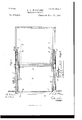
- Figure 1 is a sectional elevation of a camera provided with one form of the invention and adapted particularly for the handling of glass plates or films in suitable frames.
- 2 is a plan view of the same, a portion of the top wall of the camera being removed to dis close some of the interior parts.
- Fig. 3 is a vertical cross-section on the line 3 of Fig. 1, looking rearward.
- Fig. a is a like section on the same line, looking toward the lens.
- Fig. 5 is an elevation of the operating mechanism immediately within one of the vertical walls of the camera, said wall being removed, as on the line 5 of Fig. 3.
- Fig. 6 is a sectional elevation of a modified form of the film or plate transferring means.
- Fig. '7 is a plan view thereof.
- Fig. 8 is an enlarged detail.
- Fig. 9 is another detail.
- Figs. 10 and 11 are per; spective views of another modified form of the transferring means.
- Figs. 12 and 13 are detail elevations of a specific form of carrying device employed in the structure of Figs. 10 and 11.
- Fig. 14 is an enlarged elevation of the separator.
- Fig. 15 is a plan view of the separator-disk.
- Fig. 16 shows diagrams of the action of a separator.
- I form in a camera a screen or division-plate C, forming thereby a separate chamber or compartment D, in which on a flange or ledge B near the bottom on each the latter being carried in suitable hollow frames (one to each) with their sensitized faces downward and parallel with the bottom of the camera.
- the ledge B which may be hollow or skeletoned like a rail, is continued in the direction of the lens in an aporoximately circular form 11, terminating at the point 11 at the top of the camera, which is the distance necessary to control the movement of the plate in its transference from the vertical or position of exposure through the top slot or opening T in the screen C onto the top of the stack.
- Concentric with and on the inner side of the circular flange or ledge B is a slot J, formed in the sides of the compartment or camera, through which projects a spring-bolt, catch, or nose-piece Q, of a rotating disk or radial arm Q, (see Fig.
- a selecting and separating device 6., a device to select and separate from the stack or magazine one plate at a time preparatory to exposure, I provide in one form of my .in vention on the spindle K, on one or both sides or ends thereof, a cam M, (see Fig. 5,) of a shape approximately that shown in the drawings, suitable for operating a vertical separating-lever N, hinged at the top P and jointed at the bottom to a horizontal extension-separating link G, which is connected at its end to a transverse bar E, which carries one, two, or more separating-noses F (see Fig. 1) for engaging with the back edge of the bottom plate in the magazine.
- a cam M (see Fig. 5,) of a shape approximately that shown in the drawings, suitable for operating a vertical separating-lever N, hinged at the top P and jointed at the bottom to a horizontal extension-separating link G, which is connected at its end to a transverse bar E, which carries one, two, or more separating-nose
- U is an antifrietion-roller on lever N for contact with the cam ill, which, coming into sliding contact therewith, imparts motion to the bar E and enables the noses F to bear against and move the bottom plate from the stack and deliver it at the point Y where the spring-bolt Q at the end of the rotary arm Q engages with it in order to transfer it up the flanges H and L to the vertical position for exposure.
- the said cam M is of such a shape that a continuation of its motion through the medium of a fixed stud M, which it bears, and engaging with an eccentric extension R on the vertical lever N enables the link G and transverse bar E to reverse and make the return movement for the next plate.
- l may employ a collapsible or folding-down flap or lap S with a notch or groove L on the edge, so to furnish a seat or socket for the plate to stand in.
- One such lap is on each side of the camera at the bottom, each mounted on the shaft lV, which by its connection through shaft W with the cam-rod l worked by the cam ⁇ V raises the flaps when a plate is being drawn out in order to support it, and then lowers them flush with the bottom of the camera when the point is reached where the said plate is required to assume the angle necessary to enable the nose Q, to engage with it for sliding it up the ledges H L.
- I provide a lever (see Fig. 5,) jointed at K on the separating-lever N and at K and thence to setting-shaft V which is iixed thereon, and a setting-lever terminating at K, where its function is to press down thestud K on the shutter and thus automatically set the latter every time a plate is changed.
- he kneeling-piece Y, Fig. 5, on the end of the bar E is a trailing spring-click to enable said bar E to make the return movement at a lower level, and thus avoid scraping the surface of the lowermost plate in the magazine.
- Motion may be imparted to the parts described by a handle Y on the exterior of the camera and keyed to the spindle K, and in the general arrangement shown changes the plate for every entire revolution, the handle being locked, if desired, in position while exposure is being made.
- J, Fig. 6, is a toothed segment revolving with the shaft K, and on mot-ion being imparted thereto through the handle Y engages with the rack G to move it in one direction.
- a link G (see Fig. 8,) carrying the transverse separating-bar E, bearing the separatingnoses F, which move out the bottom plate to a distance equal to the width of the plate onto the raiser-arms L.
- These latter consist of two arms attached to a shaft N, which is connected with the free end of a lifting-lever O by a link and the crank-joint I.
- a pin fixed on the toothed segment J raises the free end of the lever 0 which, being connected by the crank-joint with the shaft N, turns the same through an angle of ninety degrees and thus raises the arms L, with the plate on them, into the vertical position shown at ll. Inimediately the plate arrives at this position the spring-clips R on the radial arm Q (see Fig. 9) spring into the free space or path at Ill and engage with the bottom edge of the plate, holding it securely in that position for exposure. After exposure the continued rotary motion of the main shaft K pushes it, at
- the proper position for the ra dial arm Q is about that shown by the dotted line H and not that shown in the drawings, where it is placed simply in order to illustrate the operation of lifting or raising the plate into the position of deposit.
- the toothed segment Q is of larger diameter than toothed segment J and therefore while the latter escapes the pinion V the former engages with it and by its aid returns the rack G and its separating-bar E into the normal position ready for drawing forward another plate.
- Fig. 8 is a detail of the separating-nose F and the kneeling-piece Y.
- transferring devices are applicable to the use of plates without carriers, as already noted, and also to the use of flat out films, provided these latter are each contained or held in a suitable rigid frame, which may be hollow, that is to say, without any opaque backing such as would be formed by a metal plate of suitable size, with the body stamped out, so as to simply leave a rim on its four sides, with the edges on two or three of such sides turned down, so as to act as retaining-flanges.
- Figs. 10, 11, 12, and 13 I adapt the transferring devices to handle fiat cut films alone and by themselves, that is to say, without being held or contained in any sheath or carrier.
- the boxlike chamber D is shown separated from the camera proper, but is intended to fit within the rear end of the camera with the vertical front end wall O in line with and fronting the lens.
- the interior of this chamber is arranged to receive a number of fiat films with their sensitive sides uppermost, the films resting upon the bottom B, which is open at its forward end to expose the forward portion of the bottom film and permit the engagement therewith of the carrying or transferring device hereinafter described.
- two endless chains, bands, or the like P that are stretched to move coincident with the top, bottom, and two ends over supporting-pulleys P the two chains or bands being connected together to operate as a single carrying or transferring instrumentality by crossbars K and K which support catches or impaling devices for taking the bottom film from the pile, move it into focus with the lens, and then deposit it on the pile of films in said chamber.
- the cross-bar K carries a pair of springpressed impaling pins, hooks, or grippers S, adapted in this instance to engage with suitably-arran ged perforations in the forward end of the lowermost film, so that on the onward movement of the chains and cross-piece it will be removed from the pile and arranged in position for exposure.
- These hooks have projecting pins 5 which are arranged to engage with cams 8 supported by a cross-piece B above the top of the chamber near its rear end, which raise the hooks to release the ex posed film and permit it to rest on the top of the pile of films in the 'cl1a1nberD.
- the other cross-picce K carries spring-pressed toes 5 adapted to engage the rear edge of the film, holding it stretched and flat while in exposing position, and aids in carrying the film onward on the movement of the chains, the toes being opened in a manner similar to the hooks and by the same cams.
- the cross-pieces K will also be duplicated, by which means it is possible to have a film always ready and waiting to be moved into exposing position.
- a device for the separation of the films in order that the grippers S may take hold of them one only at each time there is provided a device, Fig. 14:, which is in the form of a cam-shaped or screw-contoured disk E, arranged at the lower end of a vertical. shaft E at the inner side of the front end wall C.
- This disk has an overlapping section, like a nose-piece, so as to form two surfaces with knife-edges and a space between of just su Fficientwidth to take the thickness of one film and no more.
- This screw or cam shaped disk E has a knife-edge beginning from nothing and increasing by reason of its cam shape so as to gradually insert itself between the film to be separated and the rest of the pack.
- the upper end of the shaft E is connected by bevel-gearing with a transverse shaft P connecting one pair of the pulleys P the in'oportionate size and number of teeth being so adjusted that for every revolution of the operating-handle Y the screw cam-disk shall make one effective revolution, that is to say, shall completely separate one edge of the film from the pack.
- this cam on a circular boss 13 the back face of which is cut into an irregular inclined plane terminating in a drop acting upon a fixed stop F carried by the end wall 0, against which it is kept in contact by a spiral spring G, surrounding the shaft upon which it is mounted.
- This circular boss attached to the separating-cam includes a circular wedge-shaped piece P", onveloping the boss 13 for one-third of its periphery.
- I give to the cam the shape or section shown at E, Fig. 15, in which case the overlapping nose-piece may be omitted or modified to suit the thickness of the sheets in use and the degree of separation required.
- L and L are spring-claws for the purpose of holding each preceding film in position while the succeeding film is being carried over and deposited.
- These claws are actuated by the eross-carrier,which in sliding over them depresses them to an extent to enable them to bear down with their tips upon the edge of the film just previously deposited, and the succeeding film, which is then inthe carrier, is thus enabled to pass into its deposited position without the edges of one coming into collision with those of the other.
- lll M are retaining or overlapping flanges or guide-frames for enabling the film to retain its fiat positioinduring exposure and 0th erwise to control its passage.
- N are spring-blades for the purpose of adjusting the films in their place when deposited on release from the grippers S.
- the cam E revolves and its knifeedged nose becomes inserted behind the first film at the same time as the lower part of the boss B commences to give a forward motion, bending the film outward.
- the wedgeshaped piece P then also begins to insert itself in such a way as to inter-pose its own bulk between the film just separated and the one immediately behind and thus prevents the latter from following too soon.
- the cross-carrier K arrives, and the spring-hooks S sliding oif the end'of the bottom G, which up to this point resisted them, take into the perforations in the edge of the film, which is then drawn up to the position for exposure.
- A is an oblong sliding shutter working vertically in parallel guides 13*, containing two apertures A and A
- This shutter is drawn upward in one direction by the spring B and set in the other direction by means of the setting-lever K, drawing down on the stud K in the direction shown by the arrow.
- This lever in self-setting cameras is worked by the general plate-changing mechanism operating the setting-shaft
- the aperture A is surrounded on all but the top side by alight-tight casing containing a mirror at an angle of fortyfive degrees to the front.
- the shutter is set, the aperture A is opposite the lens and re mains locked in that position by means of the spring-latch L, as shown by the dotted lines L, and the rays of light falling on the mirror from the lens are reflected upward onto the screen of the finder l "he top of the casing is connected with the top of the camera by suitable light-tight flexible material, such as thin leather or other opaque textile or non-textile fabric.
- L is a trigger-shaft with a tumbler which has a short circular motion in either direction. In one direction it works the presser L which acts by releasing the bearing L" upon the latch L. On being released the sliding shutter is rapidly drawn upward, bringing the aperture A opposite the lens, and on arriving there exposure takes place until the aperture is closed by the presser-wing D coming into contact with the catch of the crank D and letting drop the spring-flap hinged at D,which,fallin g down outward over the aperture, covers the lens.
- the trigger on being turned in the opposite direction allows the shutter to rise and brings the aperture A opposite the lens the same as before, and so long as the trigger is held in the position just indicated the presserwing D is free of the crank D and exposure continues at the will of the operator untilthe trigger E is letgo, when the presser D,through action on crank D closes the flap-aperture.
- What I claim is 1.
- a magazine-camera the combination of a compartment for a quantity of separable films or plates normally out of the focal plane of the lens, a single handle rotatable only in one direction, a transferring device controlled by said handle and movable in one direction for moving the plate into the focal plane and thence into the compartment, and a cam for releasing the transferring device from the plate, as set forth.
- a magazine-camera the combination of a compartment for a quantity of separable films or plates, a single handle rotatable only in one direction, a transferring device controlled by said handle and movable in one direction for moving the film into the focal plane and thence back into the compartment, a cam for releasing the transferring device from the film, a rotatable disk separator for the films and connections with said handle for rotating said disk, as set forth.
Landscapes
- Physics & Mathematics (AREA)
- General Physics & Mathematics (AREA)
- Photographic Developing Apparatuses (AREA)
Description
(No Model.) 8 SheetsSheet 1.
S. D. WILLIAMS.
MAGAZINE GAMBRA.
No. 578,905. Patented Mar. 16,1897.
n R 1 H ii D m Q WITNESSES:\ H NVENTOR BY W QL/m dw ATTORNEYS (No Model.) 8 sheets Sheet 2 S. D. WILLIAMS MAGAZINE CAMERA.
No. 578,905. I Patented Mar. 16,1897.
l N} I) J W k v a; z
i m i b 5 E m a k] h m N E ga L: I: L
WITNESSES: m BY m /M ATTORNEY (No Model.) 8 Sheets-Sheet 3 S. D. WILLIAMS.
MAGAZINE CAMERA.
No. 578,905. Patented Mar. 16, 1897.
INVENTOR 57d i/lkw ATTORNEY9 (No Mod L) 8 Sheets-Sheet 4.
3.1). WILLIAMS MAGAZINE CAMERA.
No. 578,905. Patented Mar. 16,1897.
WITNESSES. E IWENTOR ATTORN EYQ.
(No Model.) 8 Sheets-Sheet 5 S. D WILLIAMS.
MAGAZINE CAMERA.
No. 578,905. Patented Mar. 16, 1897.
ATTORNEYS BY l in 22%, 6111. Raw
THE NQRms PETERS CO. HOYcmIYMb WASWNGYDN, D. c
6 t e e h s m e 8 h S 00 S M An I L L I W D S (No Model.)
MAGAZINE CAMERA.
No. 578,905. Patented Mar. 16, 1897 ATTORNEY S. D. WILLIAMS.
(No Model.) 8 Sheets-Sl1eet 7 MAGAZINE CAMERA.
No. 578,905. Patented Mar. 16,1897.
WWW
om. t G e h S w 6 e h S 8 S A M B AM I LO L E I W Z M n".. S
(No Model.)
No. 578,905. Patented Mar. 16,1897.
ATTORNEY? UNITED STATES PATENT OFFICE.
SAMUEL DICKINSON IVILLIAMS, OF NEXVPOR", ENGLAND.
lVlAGAZINE=CAi d ERA.
SPEOIFICATIGN forming part of Letters Patent No. 578,905, dated March 16, 1897.
A li ti fil d June 1 1, 1894. Serial No. 514,622. (No model.) Patented in England March 31, 1892, No. 6,248, June 7, 1893,110. 11,179, and October 28, 1893, No. 20,379, and in France April 4,1893,N0.229,127.
T all-whom it may concern:
Be it known that I, SAMUEL DICKINSON \VILLIAMs, a citizen of the United Kingdom of Great Britain and Ireland, residing at Newport, in the county of Monmouth, England, have invented Improvements in Magazine- Oameras, (for which I have patents in Great Britain, No. 6,2 3, bearing date March 31, 1892, No. 11,179, bearing date June 7, 1893, and No. 20,379, bearing date October 28, 1893, and in France, No. 229,127, hearing date April 4, 1893,) of which the followingis a specification.
My present invention relates to magazinecameras adapted for both glass plates and films; and it consists in the novel features hereinafter set forth.
The accompanying drawings show dilterent I embodiments of the invention, in which Figure 1 is a sectional elevation of a camera provided with one form of the invention and adapted particularly for the handling of glass plates or films in suitable frames. 2 is a plan view of the same, a portion of the top wall of the camera being removed to dis close some of the interior parts. Fig. 3 is a vertical cross-section on the line 3 of Fig. 1, looking rearward. Fig. a is a like section on the same line, looking toward the lens. Fig. 5 is an elevation of the operating mechanism immediately within one of the vertical walls of the camera, said wall being removed, as on the line 5 of Fig. 3. Fig. 6 is a sectional elevation of a modified form of the film or plate transferring means. Fig. '7 is a plan view thereof. Fig. 8 is an enlarged detail. Fig. 9 is another detail. Figs. 10 and 11 are per; spective views of another modified form of the transferring means. Figs. 12 and 13 are detail elevations of a specific form of carrying device employed in the structure of Figs. 10 and 11. Fig. 14: is an enlarged elevation of the separator. Fig. 15 is a plan view of the separator-disk. Fig. 16 shows diagrams of the action of a separator.
Referrin g to said drawings, particularly Figs. 1 to 5, I form in a camera a screen or division-plate C, forming thereby a separate chamber or compartment D, in which on a flange or ledge B near the bottom on each the latter being carried in suitable hollow frames (one to each) with their sensitized faces downward and parallel with the bottom of the camera.
Dealing especially with my improved camera in its application to the use of plates it is to be noted as one 01' the novel features of my present invention that it is the bare plates A themselves, without their being individually contained or held in any sort of sheath or holder or with any sort of backing, which I thus stack and operate in the manner hereinafter described. The fact of the plates in the stack being supported by widely-separated ledges, as described, leaves the under plate free to be moved out through a corresponding space or slit T below the divisionplate 0, the stack of plates sinking down the distance of the thickness of the plate so moved out. Thus every plate in the stack comes antomatically to occupy the position of the bottom or under plate of the stack, each in turn being thus capable of being moved out, as above described.
The ledge B, which may be hollow or skeletoned like a rail, is continued in the direction of the lens in an aporoximately circular form 11, terminating at the point 11 at the top of the camera, which is the distance necessary to control the movement of the plate in its transference from the vertical or position of exposure through the top slot or opening T in the screen C onto the top of the stack. Concentric with and on the inner side of the circular flange or ledge B is a slot J, formed in the sides of the compartment or camera, through which projects a spring-bolt, catch, or nose-piece Q, of a rotating disk or radial arm Q, (see Fig. 5,) that is located in a recess formed in each vertical wall of the camera, and which nose-piece is enabled to take hold of or engage with the rear edge of the plate after the same has been separated from the stack by being drawn from underneath. Following the contour of the circular let go 11, as also, of course, of the slot J, but in the inside position with relation to both, is a second and similar ledge L of correspondingly smaller circumference. On a rotary motion being imparted to the arm Q, the spring-bolt or nose side I stack the sensitized plates or films A, Q takes under the bottom edge of the plate,
ICO
while the top edge thereof at the corners slides along the outer circular flange II, the other surface of the plate at the middle of the side edges sliding against the inner circular ledge L. The plate being thus maintained between the outer and the inner ledges is brought into a vertical position for exposure, as in Fig. 1, after which a continuation of the same rotary motion of the arm Q continues to elevate the plate, sliding it along the remaining portion of the circular ledge and finally deposit-ing it through the opening or slot T in the top of the screen 0 onto the top of the stack, from the bottom of which it had previously been taken. Both top and bottom slots T T are made lighttight by a flexible flap T controlled by the movement of the plate through same. The circular slot J and path H cease at the point H, and the spring-bolt nose-piece Q in the arm Q in meeting the end wall of the slot yields inwardly or withdraws itself to enable the same in the continued rotation of its arm to be brought around into position to again project through said slot to recommence its plate-tran sferrin g function at the point Y "ne rotary disk or radial arm Q, on each side of the camera is connected by a spindle or main shaft K, running through the body of the camera.
For a selecting and separating device, 6., a device to select and separate from the stack or magazine one plate at a time preparatory to exposure, I provide in one form of my .in vention on the spindle K, on one or both sides or ends thereof, a cam M, (see Fig. 5,) of a shape approximately that shown in the drawings, suitable for operating a vertical separating-lever N, hinged at the top P and jointed at the bottom to a horizontal extension-separating link G, which is connected at its end to a transverse bar E, which carries one, two, or more separating-noses F (see Fig. 1) for engaging with the back edge of the bottom plate in the magazine.
U is an antifrietion-roller on lever N for contact with the cam ill, which, coming into sliding contact therewith, imparts motion to the bar E and enables the noses F to bear against and move the bottom plate from the stack and deliver it at the point Y where the spring-bolt Q at the end of the rotary arm Q engages with it in order to transfer it up the flanges H and L to the vertical position for exposure. The said cam M is of such a shape that a continuation of its motion through the medium of a fixed stud M, which it bears, and engaging with an eccentric extension R on the vertical lever N enables the link G and transverse bar E to reverse and make the return movement for the next plate. 7
As adjuncts to the ledges B, lmay employ a collapsible or folding-down flap or lap S with a notch or groove L on the edge, so to furnish a seat or socket for the plate to stand in. One such lap is on each side of the camera at the bottom, each mounted on the shaft lV, which by its connection through shaft W with the cam-rod l worked by the cam \V raises the flaps when a plate is being drawn out in order to support it, and then lowers them flush with the bottom of the camera when the point is reached where the said plate is required to assume the angle necessary to enable the nose Q, to engage with it for sliding it up the ledges H L.
I provide a lever (see Fig. 5,) jointed at K on the separating-lever N and at K and thence to setting-shaft V which is iixed thereon, and a setting-lever terminating at K, where its function is to press down thestud K on the shutter and thus automatically set the latter every time a plate is changed. he kneeling-piece Y, Fig. 5, on the end of the bar E is a trailing spring-click to enable said bar E to make the return movement at a lower level, and thus avoid scraping the surface of the lowermost plate in the magazine. The wedge or cam shaped projection X, Fig. 5, is to enable the spring nose-piece Q to dis engage itself from the slot J at the pointll, where such path ends after the plate has been deposited at the top of the margin, as thence to the point Y the nose Q slides in springpressure contact over the surface of the side or casing of the chamber D.
Motion may be imparted to the parts described by a handle Y on the exterior of the camera and keyed to the spindle K, and in the general arrangement shown changes the plate for every entire revolution, the handle being locked, if desired, in position while exposure is being made.
In a modified form, of the invention shown in Figs. 6, '7, S, and J I omit the eamprineiple combined with levers and link motion before described and substitute therefor the principle of a rack, differential toothed segments, and pinion movement.
J, Fig. 6, is a toothed segment revolving with the shaft K, and on mot-ion being imparted thereto through the handle Y engages with the rack G to move it in one direction. To this rack, on each side, is attached a link G, (see Fig. 8,) carrying the transverse separating-bar E, bearing the separatingnoses F, which move out the bottom plate to a distance equal to the width of the plate onto the raiser-arms L. These latter consist of two arms attached to a shaft N, which is connected with the free end of a lifting-lever O by a link and the crank-joint I. A pin fixed on the toothed segment J raises the free end of the lever 0 which, being connected by the crank-joint with the shaft N, turns the same through an angle of ninety degrees and thus raises the arms L, with the plate on them, into the vertical position shown at ll. Inimediately the plate arrives at this position the spring-clips R on the radial arm Q (see Fig. 9) spring into the free space or path at Ill and engage with the bottom edge of the plate, holding it securely in that position for exposure. After exposure the continued rotary motion of the main shaft K pushes it, at
the same time tilting it, as indicated by the position 11*, at an angle, as before, and finally deposits it at the top of the other plates in the chamber D. The proper position for the ra dial arm Q is about that shown by the dotted line H and not that shown in the drawings, where it is placed simply in order to illustrate the operation of lifting or raising the plate into the position of deposit. The toothed segment Q is of larger diameter than toothed segment J and therefore while the latter escapes the pinion V the former engages with it and by its aid returns the rack G and its separating-bar E into the normal position ready for drawing forward another plate.
Fig. 8 is a detail of the separating-nose F and the kneeling-piece Y.
The two forms of transferring devices already described are applicable to the use of plates without carriers, as already noted, and also to the use of flat out films, provided these latter are each contained or held in a suitable rigid frame, which may be hollow, that is to say, without any opaque backing such as would be formed by a metal plate of suitable size, with the body stamped out, so as to simply leave a rim on its four sides, with the edges on two or three of such sides turned down, so as to act as retaining-flanges.
According to another modified form of my invention illustrated, Figs. 10, 11, 12, and 13, I adapt the transferring devices to handle fiat cut films alone and by themselves, that is to say, without being held or contained in any sheath or carrier.
The boxlike chamber D is shown separated from the camera proper, but is intended to fit within the rear end of the camera with the vertical front end wall O in line with and fronting the lens. The interior of this chamber is arranged to receive a number of fiat films with their sensitive sides uppermost, the films resting upon the bottom B, which is open at its forward end to expose the forward portion of the bottom film and permit the engagement therewith of the carrying or transferring device hereinafter described. On the opposed vertical sides there are arranged two endless chains, bands, or the like P, that are stretched to move coincident with the top, bottom, and two ends over supporting-pulleys P the two chains or bands being connected together to operate as a single carrying or transferring instrumentality by crossbars K and K which support catches or impaling devices for taking the bottom film from the pile, move it into focus with the lens, and then deposit it on the pile of films in said chamber.
The cross-bar K carries a pair of springpressed impaling pins, hooks, or grippers S, adapted in this instance to engage with suitably-arran ged perforations in the forward end of the lowermost film, so that on the onward movement of the chains and cross-piece it will be removed from the pile and arranged in position for exposure. These hooks have projecting pins 5 which are arranged to engage with cams 8 supported by a cross-piece B above the top of the chamber near its rear end, which raise the hooks to release the ex posed film and permit it to rest on the top of the pile of films in the 'cl1a1nberD. There may be two of such arrangements of impaling-pins mounted on cross-pieces arranged at equidistant points on the chains. The other cross-picce K carries spring-pressed toes 5 adapted to engage the rear edge of the film, holding it stretched and flat while in exposing position, and aids in carrying the film onward on the movement of the chains, the toes being opened in a manner similar to the hooks and by the same cams. \Vhere two crosspieces K are employed, the cross-pieces K will also be duplicated, by which means it is possible to have a film always ready and waiting to be moved into exposing position.
For the separation of the films in order that the grippers S may take hold of them one only at each time there is provided a device, Fig. 14:, which is in the form of a cam-shaped or screw-contoured disk E, arranged at the lower end of a vertical. shaft E at the inner side of the front end wall C. This disk has an overlapping section, like a nose-piece, so as to form two surfaces with knife-edges and a space between of just su Fficientwidth to take the thickness of one film and no more. This screw or cam shaped disk E has a knife-edge beginning from nothing and increasing by reason of its cam shape so as to gradually insert itself between the film to be separated and the rest of the pack. The upper end of the shaft E is connected by bevel-gearing with a transverse shaft P connecting one pair of the pulleys P the in'oportionate size and number of teeth being so adjusted that for every revolution of the operating-handle Y the screw cam-disk shall make one effective revolution, that is to say, shall completely separate one edge of the film from the pack. Sometimes I mount this cam on a circular boss 13 the back face of which is cut into an irregular inclined plane terminating in a drop acting upon a fixed stop F carried by the end wall 0, against which it is kept in contact by a spiral spring G, surrounding the shaft upon which it is mounted. This circular boss attached to the separating-cam includes a circular wedge-shaped piece P", onveloping the boss 13 for one-third of its periphery. Sometimes I give to the cam the shape or section shown at E, Fig. 15, in which case the overlapping nose-piece may be omitted or modified to suit the thickness of the sheets in use and the degree of separation required.
L and L are spring-claws for the purpose of holding each preceding film in position while the succeeding film is being carried over and deposited. These claws are actuated by the eross-carrier,which in sliding over them depresses them to an extent to enable them to bear down with their tips upon the edge of the film just previously deposited, and the succeeding film, which is then inthe carrier, is thus enabled to pass into its deposited position without the edges of one coming into collision with those of the other.
lll M are retaining or overlapping flanges or guide-frames for enabling the film to retain its fiat positioinduring exposure and 0th erwise to control its passage.
N are spring-blades for the purpose of adjusting the films in their place when deposited on release from the grippers S.
On the magazine receiving its proper charge of films the action generally on motion being imparted by turning the handle of shaft 1 is the following: The cam E revolves and its knifeedged nose becomes inserted behind the first film at the same time as the lower part of the boss B commences to give a forward motion, bending the film outward. The wedgeshaped piece P then also begins to insert itself in such a way as to inter-pose its own bulk between the film just separated and the one immediately behind and thus prevents the latter from following too soon. At this point the cross-carrier K arrives, and the spring-hooks S sliding oif the end'of the bottom G, which up to this point resisted them, take into the perforations in the edge of the film, which is then drawn up to the position for exposure. After exposure the continued forward movement of the chain or band and carriers brings the film onto the top of the chamber D. The hooks S are then in their passage up the inclined plane or cams s disengaged from the film and the film deposited in its proper position in the space occupied by the-stack in said chamber. The cam E after having separated and pushed out the forward edge of the lowermost film continues its motion and passes the wedge 1 round to its thin end, and in so doing the boss B also travels out of the range of the fixed stop F and the spiral spring G is then brought into play and takes the shaft J back into the socket Q, the cam being thus rendered ready for commencing the work of separating the next film from the rest of the stack of films.
I arrange a suitable spring-catch for release by hand for instantaneous or time exposures, as hereinafter described in connection with the combined shutter and view-finder portion of my invention, but where necessary I omit such device for independent working and connection with the view-finders repeated movements and make the contin uous travel of the transferring device or the general action of the other mechanism, as described, set the shutter and release it as fast as the films are brought into position so as to enable exposures to take place in rapid and continuous succession until the charge of film or sheets in the camera be exhausted.
In the next place my improvements in cameras refer to the provision of a combined shutter and view-finder, as shown in Figs. 1 to 5.
A is an oblong sliding shutter working vertically in parallel guides 13*, containing two apertures A and A This shutter is drawn upward in one direction by the spring B and set in the other direction by means of the setting-lever K, drawing down on the stud K in the direction shown by the arrow. This lever in self-setting cameras is worked by the general plate-changing mechanism operating the setting-shaft The aperture A is surrounded on all but the top side by alight-tight casing containing a mirror at an angle of fortyfive degrees to the front. Then the shutter is set, the aperture A is opposite the lens and re mains locked in that position by means of the spring-latch L, as shown by the dotted lines L, and the rays of light falling on the mirror from the lens are reflected upward onto the screen of the finder l "he top of the casing is connected with the top of the camera by suitable light-tight flexible material, such as thin leather or other opaque textile or non-textile fabric.
L is a trigger-shaft with a tumbler which has a short circular motion in either direction. In one direction it works the presser L which acts by releasing the bearing L" upon the latch L. On being released the sliding shutter is rapidly drawn upward, bringing the aperture A opposite the lens, and on arriving there exposure takes place until the aperture is closed by the presser-wing D coming into contact with the catch of the crank D and letting drop the spring-flap hinged at D,which,fallin g down outward over the aperture, covers the lens. For time-exposure the trigger on being turned in the opposite direction allows the shutter to rise and brings the aperture A opposite the lens the same as before, and so long as the trigger is held in the position just indicated the presserwing D is free of the crank D and exposure continues at the will of the operator untilthe trigger E is letgo, when the presser D,through action on crank D closes the flap-aperture.
According to a further plan, instead of the arrangement whereby the mirror and the whole of the light-tight casing move or rise together, sliding up with the shutter, I pivot the end of the mirror J, Fig. 3, at the point Z, as indicated in Fig. 4-, the mirror occupying the line shown from Z to Z, by which arrangement it will be seen that instead of the mirror moving in a parallel plane, as before, it now, being pivoted at point Z, moves from the plane Z to the plane Z. The other parts and their action of the slide and its apertures and the rising and falling flap over aperture A and the releasing and retaining gear are all the same as before. I may also provide by connection with the general mechanism any approved device for indicating the number of exposures made.
What I claim is 1. In a magazine-camera, the combination of a compartment for a quantity of separable films or plates normally out of the focal plane of the lens, a single handle rotatable only in one direction, a transferring device controlled by said handle and movable in one direction for moving the plate into the focal plane and thence into the compartment, and a cam for releasing the transferring device from the plate, as set forth.
2. In a magazine-camera, the combination of a compartment for a quantity of separable films or plates, a single handle rotatable only in one direction, a transferring device controlled by said handle and movable in one direction for moving the film into the focal plane and thence back into the compartment, a cam for releasing the transferring device from the film, a rotatable disk separator for the films and connections with said handle for rotating said disk, as set forth.
3. In a magazine-camera, the combination film the said lens being common to the finder and to the plate or film, as set forth.
SAMUEL DICKINSON \YILLLUIS. \Vitnesses:
JoHN H. HEoK, W. F. CASBURN.
Publications (1)
| Publication Number | Publication Date |
|---|---|
| US578905A true US578905A (en) | 1897-03-16 |
Family
ID=2647591
Family Applications (1)
| Application Number | Title | Priority Date | Filing Date |
|---|---|---|---|
| US578905D Expired - Lifetime US578905A (en) | williams |
Country Status (1)
| Country | Link |
|---|---|
| US (1) | US578905A (en) |
-
0
- US US578905D patent/US578905A/en not_active Expired - Lifetime
Similar Documents
| Publication | Publication Date | Title |
|---|---|---|
| US993047A (en) | Camera. | |
| US3744389A (en) | Automatic coin-operated photographic apparatus utilizing self-developing film units | |
| US1820113A (en) | Camera | |
| US416650A (en) | Carl paul stirn | |
| US1648525A (en) | Cut-film adapter for cameras | |
| US1151221A (en) | View-changing device. | |
| US599556A (en) | flora | |
| US436347A (en) | Willard h | |
| US490117A (en) | Camera | |
| US497525A (en) | milburn | |
| US502857A (en) | Ington | |
| US621447A (en) | Magazine-camera | |
| US440427A (en) | Photographic camera | |
| US990941A (en) | Magazine-camera. | |
| US794992A (en) | Plate-holder for photographic cameras. | |
| US579882A (en) | Augusts lumiere and louis lumiere | |
| US2458769A (en) | Apparatus for the photographic reproduction of documents | |
| US356941A (en) | Photographic camera | |
| US2312472A (en) | Photo recording device | |
| US306528A (en) | Signoe op one-half to alexandee melville claek and will | |
| US501703A (en) | Photographic camera | |
| US452119A (en) | edwards | |
| US625379A (en) | Magazine-camera | |
| US501931A (en) | Photographic camera | |
| US1225039A (en) | Adjustable plate-holder attachment for cameras. |