US5785159A - Braking mechanism for railroad cars having both pneumatic and mechanical actuators - Google Patents
Braking mechanism for railroad cars having both pneumatic and mechanical actuators Download PDFInfo
- Publication number
- US5785159A US5785159A US08/659,230 US65923096A US5785159A US 5785159 A US5785159 A US 5785159A US 65923096 A US65923096 A US 65923096A US 5785159 A US5785159 A US 5785159A
- Authority
- US
- United States
- Prior art keywords
- beams
- linkage
- braking
- lever
- arm
- Prior art date
- Legal status (The legal status is an assumption and is not a legal conclusion. Google has not performed a legal analysis and makes no representation as to the accuracy of the status listed.)
- Expired - Fee Related
Links
Images


Classifications
-
- B—PERFORMING OPERATIONS; TRANSPORTING
- B61—RAILWAYS
- B61H—BRAKES OR OTHER RETARDING DEVICES SPECIALLY ADAPTED FOR RAIL VEHICLES; ARRANGEMENT OR DISPOSITION THEREOF IN RAIL VEHICLES
- B61H13/00—Actuating rail-vehicle brakes
- B61H13/20—Transmitting mechanisms
- B61H13/24—Transmitting mechanisms for cars with two axles or bogies with two axles and braking cylinder(s) for each bogie, the mechanisms at each side being interconnected
-
- B—PERFORMING OPERATIONS; TRANSPORTING
- B61—RAILWAYS
- B61H—BRAKES OR OTHER RETARDING DEVICES SPECIALLY ADAPTED FOR RAIL VEHICLES; ARRANGEMENT OR DISPOSITION THEREOF IN RAIL VEHICLES
- B61H13/00—Actuating rail-vehicle brakes
- B61H13/02—Hand or other personal actuation
Definitions
- This invention relates to a braking mechanism for braking the wheels of a railroad car.
- Rail car trucks are typically equipped with a pneumatically activated braking system having two brake beams mounted near the truck wheels.
- the beams have extensions which fit into slots or pockets formed into the truck sidewalls.
- a linkage extends between the beams and, when actuated, an air cylinder extends the linkage causing the beams to separate.
- the extensions of each beam slide simultaneously within the sidewall pockets as the beams separate. Brake shoes located on the ends of the beams then contact the wheels, stopping the car.
- This rigging consists of an under rod and lever system in which the under rod extends perpendicularly between the two brake beams and is connected at each end to a lever mounted near the end of a beam.
- Both levers (that is, the force application lever and the reaction lever), are pivotally attached to a respective beam at the lever fulcrum, the lower ends of the levers being connected together by the under rod.
- the other end of the force application lever is connected by a chain to a wheel and gear mechanism which the train operator turns to activate the brakes.
- the other end of the reaction lever is connected to the car frame as a reaction force support. When the wheel is turned, the chain pulls the activation lever which pivots, pushing the under rod toward the reaction lever. Since the other end of the reaction lever is attached to the car, the pushing of the under rod toward the lower end of the reaction lever causes the beams to separate.
- the beam extensions When the beams become misaligned during movement into a braking position, the beam extensions can become wedged at an angle within the sidewall pockets. In some instances, this "lock-up" condition renders the brakes ineffective because the brake pads are unable to contact the wheels. Conversely, the brakes can become locked in a braking position and incur damage when the car is moved during operation. In either case, the "lock-up" due to misalignment can remain or even be made worse when the operator later attempts to actuate the pneumatic braking system.
- the mechanically actuated braking mechanism cooperates with the linkage of the disconnected pneumatically actuated braking system to force the brake shoes against the car wheels with more evenly balanced braking force than possible using the prior art manual mechanisms.
- the braking force is applied to the mechanism through the chain from the wheel and gear mechanism as with conventional mechanisms.
- the chain pulls a handle lever mounted near the end of one beam.
- the other end of the handle lever is connected to a push rod which extends at an angle to an activation lever connected to the other beam.
- Another object of the invention is to provide a braking mechanism which applies substantially balanced braking force to each of the car wheels.
- Yet another object of the present invention is to provide a braking mechanism which moves the brake beams into a braking position while maintaining the parallel relationship of the beams, thereby ensuring that the beam extensions do not become wedged at an angle within the sidewall pockets.
- FIG. 1 is a perspective view of the braking mechanism of the present invention mounted to an assembled railroad car truck with a portion of the truck broken away to show details of the braking mechanism;
- FIG. 2 is an exploded perspective view of the braking mechanism of the present invention
- FIG. 3 is an exploded perspective view illustrating the interconnection between the linkage and the push rod and actuation lever of the present invention
- FIG. 4 is a perspective view of the braking mechanism of the present invention with a portion broken away to illustrate the braking mechanism in both a braking position and a stand-by position;
- FIG. 5 is a top view of the braking mechanism of the present invention.
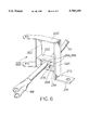
- FIG. 6 is a perspective view of the actuation lever of the present invention.
- truck assembly 10 is used, for example, to support railroad cars, and is well known to those skilled in the art. Truck assembly 10 is described below only to the extent required to ensure an understanding of the present invention.
- truck assembly 10 includes bolster 12 which supports the load being carried (e.g., a railroad car).
- Bolster 12 extends perpendicularly between parallel sidewalls 14,16 to form the shape of an "H".
- Axle 18, carrying wheels 20,22, extends parallel to bolster 12 between opposed ends 24,26 of sidewalls 14,16 respectively.
- Another axle 28, carrying wheels 30,32 similarly extends between ends 34,36.
- Brake beams 38,40 also extend between sidewalls 14,16 parallel to bolster 12.
- Beams 38,40 have extensions 42,44,46,48 at ends 50,52,54,56 respectively (shown in FIG. 2) which are suspended within pockets 58 (only one shown in FIG. 1) of sidewalls 14,16.
- Beam 38 carries brake pad 60 in substantial alignment with wheel 30 at end 50 and brake pad 62 in substantial alignment with wheel 32 at end 52.
- beam 40 carries brake pad 64 in substantial alignment with wheel 20 at end 54 and brake pad 66 in substantial alignment with wheel 22 at end 56.
- Linkage extends through bolster 12 and is attached to beams 38,40 as described in U.S. Pat. No. 5,259,485.
- linkage 68 includes actuation rod 70, brake lever 72, force application levers 74,76, stabilizer bars 78,80, bracket 82, and slack adjuster 84.
- Actuation rod 70 extends from pneumatic actuator 86, or cylinder, centrally mounted to beam 38 and terminates with coupling device or clevis 88.
- Clevis 88 is aligned with bore 90 which extends through end 92 of brake lever 72.
- Stabilizer bars 78,80 extend from bracket 82 and are movably secured to clevis 88 and brake lever 72 with pin 94.
- pin 94 When linkage 68 is assembled, pin 94 extends through openings 96,98 in stabilizer bars 78,80 respectively, which are aligned with bore 90 and clevis 88. Recessed portion 100 extends across brake lever 72. Force application levers 74,76 are pivotally connected between bracket 82, which is fixedly attached to beam 40, and brake lever 72 as shown in FIG. 2. End 102 of brake lever 72 is connected to clevis 104 of slack adjuster 84 in a manner similar to the connection between clevis 88 of actuating rod 70 and end 92. Opposed end 106 of slack adjuster 84 is connected to beam 38.
- FIGS. 2 and 3 show braking mechanism 200 of the present invention including handle lever 202, push rod 204, and actuation lever 206.
- handle lever 202 is an elongated flattened bar having ends 208 and 210 which are curved in a direction opposing the application of braking force to handle lever 202 as will be further explained below.
- Handle lever 202 is connected to brake beam 38 at a location offset from the center of beam 38 through clevis 212 as shown in FIG. 2.
- Clevis 212 is movably attached to handle lever 202 at fulcrum 214.
- the movable connection between clevis 212 and lever 202 can be accomplished using a variety of conventional fastening means including locking pin 216, a rod and cotter pin combination, a nut and bolt combination, and other means.
- the exemplary embodiment is described as using locking pins for most such movable connections.
- End 210 of handle lever 202 is attached to the brake application means which, in the exemplary embodiment, includes chain 218 connected to a geared handcrack (not shown) as is commonly employed in the art.
- End 208 of handle lever 202 is movably connected to vertical clevis end 218 of push rod 204 using locking pin 220.
- Push rod 204 extends diagonally between beams 38,40 from vertical clevis end 218 to horizontal clevis end 222 as is best shown in FIG. 5. Push rod 204 extends under beams 38,40 to avoid interference with bolster 12 when beams 38,40 are mounted to truck assembly 10 as will be described in further detail below.
- lever 206 includes vertical support 224 which has sides 226, 228. Upper arm 230, middle arm 232, and lower arm 234 extend from side 226 of vertical support 224 in substantially parallel, spaced relationship. Upper arm 230 includes segment 236 which is attached to vertical support 224 by welding or other suitable attachment means, and portion 238 which extends at an angle from the longitudinal axis of segment 236 defined by bend 240.
- lower arm 234 includes segment 242 which is attached to vertical support 224, and portion 244 which diverges from the longitudinal axis of segment 242 according to bend 246.
- Upper arm 230 portion 238 defines bore 248.
- Lower arm 234 portion 244 defines bore 250.
- Bore 248 is aligned with opening 252 which extends through flange 254 of bracket 82.
- Bore 250 is similarly aligned with opening 256 which extends through flange 258.
- Lock pin 260 extends through bore 248, flange opening 252, bores 248,250 of force application levers 74,76, flange opening 256, and bore 250 to secure actuation lever 206 and application levers 74, 76 to bracket 82.
- Lever 206 also includes brace 262 which extends between upper arm 230 and lower arm 234.
- Middle arm 232 is also connected to brace 262, and cooperates with vertical support 224, lower arm 234, and brace 262, to form substantially rectangular opening 264.
- opposed ridges 266,268 extend into opening 264 from middle arm 232 and lower arm 234 respectively.
- Actuation rod 70 of linkage 68 extends through opening 264 between ridges 266,268. Ridges 266,268 cooperate to form a curved coupling to conform to the shape of ring 270 which extends circumferentially from actuating rod 70 near clevis 88.
- push arm 272 extends perpendicularly from the lowermost end of vertical support 224 along a longitudinal axis which is substantially aligned with the longitudinal axes of upper arm 230, middle arm 232, and lower arm 234. As shown in FIG. 5, push arm 272 extends from vertical support 224 in a direction opposing the extension of segments 236,242 and middle arm 232. Push arm 272 defines bore 274 for accepting pin 276 to movably secure horizontal clevis 222 of push rod 204 to push arm 272.
- brake beams 38,40 are pneumatically actuated by linkage 68 driven by cylinder 86.
- the operator actuates cylinder 86 which forces actuation rod 70 away from beam 38.
- clevis 88 pushes against end 92 of brake lever 72 which causes brake lever 72 to pivot about pin 260.
- end 102 forces clevis 104 of slack adjuster 84 toward beam 38.
- slack adjuster 84 translates part of the force generated by cylinder 86 back to beam 38.
- slack adjuster 84 When air pressure is removed from cylinder 86, slack adjuster 84, which is biased to elongate, extends, causing brake lever 72 to pivot so that actuation rod 70 moves, without resistance from air cylinder 86, toward cylinder 86. Brake beams 38,40 thus move toward one another while maintaining a parallel relationship, simultaneously disengaging brake pads 60,62,64,66 from wheels 30,32,20,22 respectively, until beams 38,40 come to rest in a standby position.
- Braking mechanism 200 of the present invention operates linkage 68 to achieve a similar application of braking force without pneumatics.
- FIG. 4 illustrates braking mechanism 200 in a standby position (shown in solid lines) and a braking position (shown in dashed lines).
- air cylinder 86 cannot brake the car.
- the operator applies the brakes manually by turning a geared wheel crank (not shown) which pulls chain 218 longitudinally away from handle lever 202.
- End 210 of handle 202 pivots about fulcrum 214 of handle 202 into a braking position as illustrated by the dashed lines of FIG. 4.
- end 208 of handle 202 forces push arm 204 toward beam 40. Since clevis 212 is mounted on beam 38 at a location closer to pad 62 than pad 60, a larger component of the force applied through chain 218 to handle 202 translates to pad 62 at end 52 than translates to pad 60 at end 50.
- the remaining braking force is imparted through push rod 204 to push arm 272 of actuation lever 206.
- push rod 204 moves toward beam 40 in response to handle 202, horizontal clevis 222 urges push arm 272 to rotate outwardly from beam 40 about pin 260.
- middle arm 232 and lower arm 234 carry ridges 266,268 respectively away from beam 40 into contact with ring 270 of actuation rod 70.
- ridges 266,268 enable lever 206 to move actuation rod 70 away from cylinder 86 in a manner similar to the motion imparted to actuation rod 70 by cylinder 86 during pneumatic braking.
- actuation rod 204 causes brake lever 72 to pivot such that clevis 104 forces slack adjuster 84 toward brake beam 38. Braking force is transferred to beam 40 near the center of beam 40 through force application levers 74,76. Beam 40 moves toward wheels 20,22 as extensions 42,44 slide within pockets 58. Ultimately, when beam 40 reaches a braking position, brake pads 64,66 contact wheels 20,22 respectively.
- actuation lever 206 operates linkage 68, normally used during pneumatic braking, so that all four brake pads 60,62,64,66 contact truck wheels 30,32,20,22 at substantially the same time with substantially the same braking force.
Landscapes
- Engineering & Computer Science (AREA)
- Mechanical Engineering (AREA)
- Braking Arrangements (AREA)
Abstract
Description
Claims (12)
Priority Applications (1)
| Application Number | Priority Date | Filing Date | Title |
|---|---|---|---|
| US08/659,230 US5785159A (en) | 1996-06-05 | 1996-06-05 | Braking mechanism for railroad cars having both pneumatic and mechanical actuators |
Applications Claiming Priority (1)
| Application Number | Priority Date | Filing Date | Title |
|---|---|---|---|
| US08/659,230 US5785159A (en) | 1996-06-05 | 1996-06-05 | Braking mechanism for railroad cars having both pneumatic and mechanical actuators |
Publications (1)
| Publication Number | Publication Date |
|---|---|
| US5785159A true US5785159A (en) | 1998-07-28 |
Family
ID=24644602
Family Applications (1)
| Application Number | Title | Priority Date | Filing Date |
|---|---|---|---|
| US08/659,230 Expired - Fee Related US5785159A (en) | 1996-06-05 | 1996-06-05 | Braking mechanism for railroad cars having both pneumatic and mechanical actuators |
Country Status (1)
| Country | Link |
|---|---|
| US (1) | US5785159A (en) |
Cited By (14)
| Publication number | Priority date | Publication date | Assignee | Title |
|---|---|---|---|---|
| US6332515B1 (en) * | 1997-06-13 | 2001-12-25 | New York Air Brake Corp. | Truck mounted brake beam |
| US6398314B2 (en) * | 1999-07-02 | 2002-06-04 | Miner Enterprises, Inc. | Brake system for rail cars |
| EP1457402A1 (en) * | 2003-02-06 | 2004-09-15 | Knorr-Bremse Systeme für Schienenfahrzeuge GmbH | Tread brake unit for a bogie of a railway vehicle |
| USD497571S1 (en) | 2003-06-05 | 2004-10-26 | New York Air Brake Corporation | Railcar beam |
| USD497837S1 (en) | 2003-06-05 | 2004-11-02 | New York Air Brake Corporation | Railcar beam |
| US20070209886A1 (en) * | 2006-03-07 | 2007-09-13 | Tnc Rail, Llc. | Truck mounted brake assembly |
| US7527131B1 (en) * | 2008-10-06 | 2009-05-05 | Amsted Rail Company, Inc. | Railway freight car truck |
| US20110272226A1 (en) * | 2010-05-06 | 2011-11-10 | Stucki De Mexico S, De R.L. De C.V. | Connecting rod |
| US9511782B2 (en) | 2015-02-11 | 2016-12-06 | Amsted Rail-Faiveley LLC | Braking systems for railway cars |
| US9725102B2 (en) | 2015-02-11 | 2017-08-08 | Amsted Rail Company, Inc. | Braking systems for railway cars |
| US9855960B2 (en) | 2016-05-23 | 2018-01-02 | Amsted Rail Company, Inc. | Braking systems for railway cars |
| US9896113B2 (en) | 2016-05-23 | 2018-02-20 | Amsted Rail Company, Inc. | Braking systems for railway cars |
| US9937935B2 (en) | 2016-05-23 | 2018-04-10 | Amsted Rail Company, Inc. | Braking systems for railway cars |
| US20180194375A1 (en) * | 2015-04-30 | 2018-07-12 | Siemens Ag Oesterreich | Device for Securing Braking Devices to a Chassis Frame of a Rail Vehicle |
Citations (4)
| Publication number | Priority date | Publication date | Assignee | Title |
|---|---|---|---|---|
| US2375727A (en) * | 1941-12-29 | 1945-05-08 | Timken Roller Bearing Co | Car truck |
| US4312428A (en) * | 1980-02-08 | 1982-01-26 | Ellcon-National, Inc. | Truck mounted brake apparatus |
| US5259485A (en) * | 1992-10-05 | 1993-11-09 | Triax Tube Company | Truck car braking system |
| US5361876A (en) * | 1993-05-04 | 1994-11-08 | Ellcon National, Inc. | Truck mounted brake apparatus |
-
1996
- 1996-06-05 US US08/659,230 patent/US5785159A/en not_active Expired - Fee Related
Patent Citations (4)
| Publication number | Priority date | Publication date | Assignee | Title |
|---|---|---|---|---|
| US2375727A (en) * | 1941-12-29 | 1945-05-08 | Timken Roller Bearing Co | Car truck |
| US4312428A (en) * | 1980-02-08 | 1982-01-26 | Ellcon-National, Inc. | Truck mounted brake apparatus |
| US5259485A (en) * | 1992-10-05 | 1993-11-09 | Triax Tube Company | Truck car braking system |
| US5361876A (en) * | 1993-05-04 | 1994-11-08 | Ellcon National, Inc. | Truck mounted brake apparatus |
Cited By (20)
| Publication number | Priority date | Publication date | Assignee | Title |
|---|---|---|---|---|
| US6332515B1 (en) * | 1997-06-13 | 2001-12-25 | New York Air Brake Corp. | Truck mounted brake beam |
| US6398314B2 (en) * | 1999-07-02 | 2002-06-04 | Miner Enterprises, Inc. | Brake system for rail cars |
| EP1457402A1 (en) * | 2003-02-06 | 2004-09-15 | Knorr-Bremse Systeme für Schienenfahrzeuge GmbH | Tread brake unit for a bogie of a railway vehicle |
| US20040200679A1 (en) * | 2003-02-06 | 2004-10-14 | Knorr-Bremse Systeme Fur Schienenfahrzeuge Gmbh | Block brake device of a bogie of a rail vehicle |
| US7165659B2 (en) | 2003-02-06 | 2007-01-23 | Knorr-Bremse Systeme Fur Schienenfahrzeuge Gmbh | Block brake device of a bogie of a rail vehicle |
| USD497571S1 (en) | 2003-06-05 | 2004-10-26 | New York Air Brake Corporation | Railcar beam |
| USD497837S1 (en) | 2003-06-05 | 2004-11-02 | New York Air Brake Corporation | Railcar beam |
| US20070209886A1 (en) * | 2006-03-07 | 2007-09-13 | Tnc Rail, Llc. | Truck mounted brake assembly |
| US7472775B2 (en) * | 2006-03-07 | 2009-01-06 | Tnc Rail, Llc | Truck mounted brake assembly |
| AU2009200854B2 (en) * | 2008-10-06 | 2012-10-04 | Amsted Rail Company, Inc. | Railway freight car truck |
| US7527131B1 (en) * | 2008-10-06 | 2009-05-05 | Amsted Rail Company, Inc. | Railway freight car truck |
| US20110272226A1 (en) * | 2010-05-06 | 2011-11-10 | Stucki De Mexico S, De R.L. De C.V. | Connecting rod |
| US8640834B2 (en) * | 2010-05-06 | 2014-02-04 | Stucki De Mexico, S. De R.L. De C.V. | Connecting rod |
| US9511782B2 (en) | 2015-02-11 | 2016-12-06 | Amsted Rail-Faiveley LLC | Braking systems for railway cars |
| US9725102B2 (en) | 2015-02-11 | 2017-08-08 | Amsted Rail Company, Inc. | Braking systems for railway cars |
| US20180194375A1 (en) * | 2015-04-30 | 2018-07-12 | Siemens Ag Oesterreich | Device for Securing Braking Devices to a Chassis Frame of a Rail Vehicle |
| US11091181B2 (en) * | 2015-04-30 | 2021-08-17 | Siemens Mobility Austria Gmbh | Device for securing braking devices to a chassis frame of a rail vehicle |
| US9855960B2 (en) | 2016-05-23 | 2018-01-02 | Amsted Rail Company, Inc. | Braking systems for railway cars |
| US9896113B2 (en) | 2016-05-23 | 2018-02-20 | Amsted Rail Company, Inc. | Braking systems for railway cars |
| US9937935B2 (en) | 2016-05-23 | 2018-04-10 | Amsted Rail Company, Inc. | Braking systems for railway cars |
Similar Documents
| Publication | Publication Date | Title |
|---|---|---|
| US5069312A (en) | Handbrake for single-cylinder truck-mounted railway car brake | |
| US5785159A (en) | Braking mechanism for railroad cars having both pneumatic and mechanical actuators | |
| US5259485A (en) | Truck car braking system | |
| US6279689B1 (en) | Hydraulic parking brake for a railroad vehicle braking system | |
| US20080035432A1 (en) | Railway car hand brake lever | |
| US6241057B1 (en) | Hydraulic parking brake lever arrangement for a railroad vehicle braking system | |
| US3780837A (en) | Single cylinder truck-mounted brake | |
| US4312428A (en) | Truck mounted brake apparatus | |
| US6932535B2 (en) | Pivoting joint for pivotally joining a brake head to a brake beam | |
| CA2298286C (en) | An adapter system for a railway vehicle braking system | |
| CA2122883C (en) | Truck mounted brake apparatus | |
| CA2442787C (en) | Improved hand brake lever interface for single-cylinder truck-mounted railway car brake | |
| US5947236A (en) | Truck mounted brake for standard and premium ride trucks | |
| US6551003B1 (en) | Joint for pivotally joining a brake head to a brake beam | |
| US7341128B2 (en) | Disk brake arranged TMX | |
| EP0217589A2 (en) | Rail car brake apparatus | |
| US4039051A (en) | Disc brake construction, especially for rail vehicles | |
| CN110944897A (en) | Truck mounted brake system for railway vehicle | |
| US4508197A (en) | Handbrake system for railway car | |
| EP1535817B1 (en) | Improved hand brake lever interface for single-cylinder truck-mounted railway car brake | |
| US3696892A (en) | Brake head-centering device for railway brake apparatus | |
| CA1212635A (en) | Hand brake arrangement | |
| EP0344667B1 (en) | A detachable rigid joint | |
| EP0085252B1 (en) | A disc brake and vehicle axle assembly and a disc brake caliper assembly | |
| US4090412A (en) | Handbrake linkage for transmitting mechanical braking force between adjacent rail vehicles |
Legal Events
| Date | Code | Title | Description |
|---|---|---|---|
| AS | Assignment |
Owner name: TRIAX-DAVIS, INC., MICHIGAN Free format text: ASSIGNMENT OF ASSIGNORS INTEREST;ASSIGNOR:MANYEK, LEONARD;REEL/FRAME:008035/0640 Effective date: 19960517 |
|
| AS | Assignment |
Owner name: TRIAX-YSD, INC., OHIO Free format text: ASSIGNMENT OF ASSIGNORS INTEREST;ASSIGNOR:TRIAX-DAVIS INC.;REEL/FRAME:009678/0837 Effective date: 19981117 |
|
| REMI | Maintenance fee reminder mailed | ||
| LAPS | Lapse for failure to pay maintenance fees | ||
| LAPS | Lapse for failure to pay maintenance fees |
Free format text: PATENT EXPIRED FOR FAILURE TO PAY MAINTENANCE FEES (ORIGINAL EVENT CODE: EXP.); ENTITY STATUS OF PATENT OWNER: SMALL ENTITY |
|
| STCH | Information on status: patent discontinuation |
Free format text: PATENT EXPIRED DUE TO NONPAYMENT OF MAINTENANCE FEES UNDER 37 CFR 1.362 |
|
| FP | Lapsed due to failure to pay maintenance fee |
Effective date: 20020728 |
|
| AS | Assignment |
Owner name: BARBER BRAKE BEAM LLC, ILLINOIS Free format text: ASSIGNMENT OF ASSIGNORS INTEREST;ASSIGNOR:HARBOR BRAKE BEAM CO.;REEL/FRAME:018767/0038 Effective date: 20070110 |
|
| AS | Assignment |
Owner name: BARBER BRAKE BEAM LLC, ILLINOIS Free format text: REVISED ASSIGNMENT;ASSIGNOR:HARBOR BRAKE BEAM CO.;REEL/FRAME:019390/0657 Effective date: 20070110 |