US577957A - Oil-measuring pump - Google Patents
Oil-measuring pump Download PDFInfo
- Publication number
- US577957A US577957A US577957DA US577957A US 577957 A US577957 A US 577957A US 577957D A US577957D A US 577957DA US 577957 A US577957 A US 577957A
- Authority
- US
- United States
- Prior art keywords
- oil
- cylinder
- piston
- gooseneck
- valve
- Prior art date
- Legal status (The legal status is an assumption and is not a legal conclusion. Google has not performed a legal analysis and makes no representation as to the accuracy of the status listed.)
- Expired - Lifetime
Links
Images

Classifications
-
- F—MECHANICAL ENGINEERING; LIGHTING; HEATING; WEAPONS; BLASTING
- F04—POSITIVE - DISPLACEMENT MACHINES FOR LIQUIDS; PUMPS FOR LIQUIDS OR ELASTIC FLUIDS
- F04B—POSITIVE-DISPLACEMENT MACHINES FOR LIQUIDS; PUMPS
- F04B49/00—Control, e.g. of pump delivery, or pump pressure of, or safety measures for, machines, pumps, or pumping installations, not otherwise provided for, or of interest apart from, groups F04B1/00 - F04B47/00
- F04B49/22—Control, e.g. of pump delivery, or pump pressure of, or safety measures for, machines, pumps, or pumping installations, not otherwise provided for, or of interest apart from, groups F04B1/00 - F04B47/00 by means of valves
- F04B49/24—Bypassing
Definitions
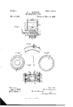
- Figure 1 is a side elevation of my invention.
- Fig. 2 is a front elevation of the upper portion of the pump.
- Fig. 3 is a front elevation of the lower portion thereof.
- Fig. 4 is an enlarged section on the line a; of Fig. 1.
- Fig. 5 is a section taken through the arch or crown of the gooseneck deliverypipe and the vent-valve carried thereby.
- Fig. 6 is a middle vertical section taken through the several sections of which the piston is composed.
- Fig. 7 is a top plan view of the lower section of the piston, and
- Fig. 8 is a plan view of one of the packing-rings.
- the present invention is an improvement on the oil-measuring pump described in United States Letters Patent No. 486,596, under date of November 22, 1892, and has for its object to materially improve the construction therein set forth in certain particulars whereby the pump may possess advantages additional to those belonging to the construction already patented.
- valve controlling the admission of the oil from the supply-tank into the pump-cylinder; in the addition of a certain gage or index by which the quantity of oil pumped into the cylinder and intended to be delivered to the customer can be measured and ascertained at a glance; in the addition of a certain vent-valve in the gooseneck through which the oil is discharged; in the improved piston and packing therefor, and in other and further details to be more particularly hereinafter referred to.
- 1 represents a suitable standard, the base 2 of which can be secured to any suitable support, table, counter, or the like. Passing freely through said base and extending both below and above the same is a reciprocating piston -rod or plunger 3, the base of which carries a piston operating in the .open cylinder 4, secured to the base 2.
- the cylinder is partially secured to the base 2 by means of a rigid bar 5, de pending from said base, the lower end of the bar 5 being secured to the hollow casting 6, forming the base of the cylinder and subserving the purpose of retaining the check-valves by which the flow of the liquid into and from the cylinder 4 is governed.
- the cylinder is additionally supported by means of the delivery-pipe 7, whose bas'ecommunicates with the outlet-passage from the casting 6, the upper end of the pipe 7 passing through and being secured to the base 2 of the supportingstandard.
- a swinging are 9 Pivoted to the free end of abracket or arm 8, forming a part of the standard, is a swinging are 9, whose periphery is grooved for the reception of the adjacently-disposed elastic cables 10 11, the lower end of the cable 10 being secured at a convenient point to the upper piston extension and the upper end of said cable being secured to theupper end of the arc, while the upper end of the cable 11 is secured to the upper end of the piston extension, the opposite end of said cable being secured to the lower extremity of the periphery of the arc.
- the swinging arc is provided with a suitable handle or extension 12, which serves to swing the are up or down and accordingly draw up or force down the pistonrod or plunger 3, operating within the pumpcylinder.
- abolt 14 whose inner end is adapted to strike the head 15 of a bolt adjustably mounted in a slot 16 at the upper end of the standard, thereby preventing the swinging of the are beyond pipe 7.
- an index or pointer 20 Carried by the standard 1 and projeeting outwardly and forwardly therefrom is an index or pointer 20, which cooperates with certain divisionqnarks l, 2, 3, 4, &c., of an index-plate 21, secured to the front face of the upper extension of the plunger.
- the division-marks are arbitrary and may represent quarts, pints, or gallons. hen the pin 17 is pulled outto its full extent, so that the arc has free swing, the operator can swing the same and draw up the plunger (or piston-rod) and cause the latter to stop when any particular division-mark on the index-plate comes opposite the index or pointer 20. In this way the exact quantity of oil can always be pumped into the cylinder at one stroke of the piston and forced from it on the next or down stroke.
- valves for controlling the liquid which passes into the eylinder are best described in connection with the casting 6, within which they are housed and mounted.
- the contracted and depending portion or mouth of the casting 6 is interiorly screw-threaded, (see Fig. 4,) said screw-threaded end being adapted to receive the cylindrical valve-casing 22, within whose smooth bore is adapted to operate and be guided the ribbed extension 23 of a disk check-valve 24, the periphery of which is adapted to seat against the upper bevel edge of the casing.
- a ring or ledge 25 Forming part of the disk of the valve and projecting upwardly therefrom is a ring or ledge 25, having a series of V-shaped grooves 26.
- a second valvecasing 22' Located at a suitable distance from and separated by a space from the upper edge of the ledge 25 is the base of a second valvecasing 22', similar to but smaller than the casing 22 and adapted to retain a similar valve 24, having a terminal ledge 25 located below a depression or cavity 27, formed in the superposed wall 28 of the exit-passage 29, leading from the casting to the discharge
- a passage 30, which communicates with the upper end of the casting or that end secured directly to the open base of the cylinder 4:.
- a sieve 32 Secured to and carried by a peripheral rim 31, formed along the outer inclined surface of the mouth of the casting, is a sieve 32 of usual construction.
- the lower end of the cylinder is inserted into the tank or vessel from which the oil is to be extracted. IVith the upward stroke of the plunger the oil rushes into the casing 22 of the lower valve, raising the latter off its seat and passing, as indicated by the arrow in Fig. 4, through the passage 30 into the lower portion of the pump-cylinder 4, the quantity entering the cylinder depending on the amount of upward swing of the are or upward stroke of the plunger, such quantity being indicated by the division-marks of the index-plate carried by the upper extension of the plunger, which cooperate with the pointer 20, carried by the standard.
- the loops or coils being prevented from dropping or working out of their confines by the flanges 43 and 44 of the lower section and cup, respectively.
- the several sections are held together by passing a ring 45 over the stem 37 of the lower section, the ring having a reduced portion 46, through which the lower end of the plunger orpiston-rod freely passes, the plunger carrying a head 47, confined in the space 48 formed between the upper edge of the stem 37 and the upper wall of the ring 45. In this way sufficient lateral play is permitted or allowed the piston-rod should the cylinder, for any reason, not be true with respect to the other portions of the machine.
- the device never leaks.
- the pump is responsive to the smallest stroke of the piston-rod.
- the vent-valve in the gooseneck the ejection of all the oil measured to the customer is speedily accomplished and insured, and by the use of the index-plate any suitable and predetermined quantity of oil can easily be measured out and served to the customer.
Landscapes
- Engineering & Computer Science (AREA)
- Mechanical Engineering (AREA)
- General Engineering & Computer Science (AREA)
- Reciprocating Pumps (AREA)
Description
A. H. HERRON. 01L MEASURING PUMP.
2 Sheets-Sheet 1.
(No Model.)
No. 577,957. Patented Mar. 2, 1897.
TN! uonms mus 00,, PNOYO-LITNQ. WASHINGTON. u. c.
(No Model.) 2 Sheets-Sheet 2 A. H. HERRON. OIL MEASURING PUMP.
No. 577,957. Patented Mar. 2, 18.97.
I 1y I198 wifiwwwo gmvzwboz TN: xoams Prrcns co. PMo'ro-uma. wAsmNcYom n. c,
NITED STATES PATENT OFFICE.
AL H. HERRON, OF ST. LOUIS, MISSOURI, ASSIGNOR TO THE ANTHONY WAYNE MANUFACTURING COMPANY, OF SAME PLACE AND FORT WVAYNE, INDIANA.
OIL-MEASURING PUMP.
SPECIFICATION formingpart of Letters Patent No. 577,957, dated March 2, 1897- Applieation filed May 11, 1896. Serial No. 591,125. (No model.) 7
In the drawings, Figure 1 is a side elevation of my invention. Fig. 2 is a front elevation of the upper portion of the pump. Fig. 3 is a front elevation of the lower portion thereof. Fig. 4 is an enlarged section on the line a; of Fig. 1. Fig. 5 is a section taken through the arch or crown of the gooseneck deliverypipe and the vent-valve carried thereby. Fig.
6 is a middle vertical section taken through the several sections of which the piston is composed. Fig. 7 is a top plan view of the lower section of the piston, and Fig. 8 is a plan view of one of the packing-rings.
The present invention is an improvement on the oil-measuring pump described in United States Letters Patent No. 486,596, under date of November 22, 1892, and has for its object to materially improve the construction therein set forth in certain particulars whereby the pump may possess advantages additional to those belonging to the construction already patented. These particulars consist in the specific construction of the valve controlling the admission of the oil from the supply-tank into the pump-cylinder; in the addition of a certain gage or index by which the quantity of oil pumped into the cylinder and intended to be delivered to the customer can be measured and ascertained at a glance; in the addition of a certain vent-valve in the gooseneck through which the oil is discharged; in the improved piston and packing therefor, and in other and further details to be more particularly hereinafter referred to.
In detail the invention may be described as follows:
Referring to the drawings, 1 represents a suitable standard, the base 2 of which can be secured to any suitable support, table, counter, or the like. Passing freely through said base and extending both below and above the same is a reciprocating piston -rod or plunger 3, the base of which carries a piston operating in the .open cylinder 4, secured to the base 2. The cylinder is partially secured to the base 2 by means of a rigid bar 5, de pending from said base, the lower end of the bar 5 being secured to the hollow casting 6, forming the base of the cylinder and subserving the purpose of retaining the check-valves by which the flow of the liquid into and from the cylinder 4 is governed. The cylinder is additionally supported by means of the delivery-pipe 7, whose bas'ecommunicates with the outlet-passage from the casting 6, the upper end of the pipe 7 passing through and being secured to the base 2 of the supportingstandard.
Pivoted to the free end of abracket or arm 8, forming a part of the standard, is a swinging are 9, whose periphery is grooved for the reception of the adjacently-disposed elastic cables 10 11, the lower end of the cable 10 being secured at a convenient point to the upper piston extension and the upper end of said cable being secured to theupper end of the arc, while the upper end of the cable 11 is secured to the upper end of the piston extension, the opposite end of said cable being secured to the lower extremity of the periphery of the arc. The swinging arc is provided with a suitable handle or extension 12, which serves to swing the are up or down and accordingly draw up or force down the pistonrod or plunger 3, operating within the pumpcylinder.
The parts thus far described are essentially the same as those of the patented construction above referred to, and to these I lay no claim.
Adjustable in a curved slot 13 nearthe base of the periphery of the swinging arc is abolt 14, whose inner end is adapted to strike the head 15 of a bolt adjustably mounted in a slot 16 at the upper end of the standard, thereby preventing the swinging of the are beyond pipe 7.
the limits of what is intended shall be its extreme stroke in one direction. Carried by and sliding in an opening of the handle portion 12, at a point which liesin the path of the are described by the bolt 14, is a pin 17, limited bya head 18 and expanded end 19, which, when forced inwardly, as indicated in Fig. 2, is adapted to strike the head of the bolt 15 when the are has described only half a stroke. In this way the degree to which the are 9 is swung and the distance to which the pistonrod shall be operated, and consequently the quantity of liquid pumped for any stroke of the piston, are accordingly governed and con trolled. Carried by the standard 1 and projeeting outwardly and forwardly therefrom is an index or pointer 20, which cooperates with certain divisionqnarks l, 2, 3, 4, &c., of an index-plate 21, secured to the front face of the upper extension of the plunger. The division-marks are arbitrary and may represent quarts, pints, or gallons. hen the pin 17 is pulled outto its full extent, so that the arc has free swing, the operator can swing the same and draw up the plunger (or piston-rod) and cause the latter to stop when any particular division-mark on the index-plate comes opposite the index or pointer 20. In this way the exact quantity of oil can always be pumped into the cylinder at one stroke of the piston and forced from it on the next or down stroke.
The valves for controlling the liquid which passes into the eylinderare best described in connection with the casting 6, within which they are housed and mounted. The contracted and depending portion or mouth of the casting 6 is interiorly screw-threaded, (see Fig. 4,) said screw-threaded end being adapted to receive the cylindrical valve-casing 22, within whose smooth bore is adapted to operate and be guided the ribbed extension 23 of a disk check-valve 24, the periphery of which is adapted to seat against the upper bevel edge of the casing.
Forming part of the disk of the valve and projecting upwardly therefrom is a ring or ledge 25, having a series of V-shaped grooves 26. Located at a suitable distance from and separated by a space from the upper edge of the ledge 25 is the base of a second valvecasing 22', similar to but smaller than the casing 22 and adapted to retain a similar valve 24, having a terminal ledge 25 located below a depression or cavity 27, formed in the superposed wall 28 of the exit-passage 29, leading from the casting to the discharge Leading from the mouth of the casting is a passage 30, which communicates with the upper end of the casting or that end secured directly to the open base of the cylinder 4:. Secured to and carried by a peripheral rim 31, formed along the outer inclined surface of the mouth of the casting, is a sieve 32 of usual construction.
The lower end of the cylinder is inserted into the tank or vessel from which the oil is to be extracted. IVith the upward stroke of the plunger the oil rushes into the casing 22 of the lower valve, raising the latter off its seat and passing, as indicated by the arrow in Fig. 4, through the passage 30 into the lower portion of the pump-cylinder 4, the quantity entering the cylinder depending on the amount of upward swing of the are or upward stroke of the plunger, such quantity being indicated by the division-marks of the index-plate carried by the upper extension of the plunger, which cooperate with the pointer 20, carried by the standard. Upon the downward stroke of the plunger 3 the lower valve closes or becomes seated, the pressure of the oil raising the upper valve and allowing the oil to pass by it and flow into the passage 29, whence it is forced into the delivery-pipe 7 and its gooseneck extension 33. For a large quantity of oil, as, for example, a gallon, there is no difliculty in forcing the entire volume through the gooseneck, but with small quantities, such, for example, as a pint or halfpint, the portion of the oil contained in the gooseneck between the open end thereof and the crown of the arch of the neck is apt to lodge in the gooseneck, coming out drop by drop only. To insure that thisportion of the oil is delivered rapidly, I place a vent-tube 3% at the crown of the arch of the gooseneck, the inner or lower end of the tube being inclined outwardly or toward the opening of the gooseneck and having a sensitive-flap vent-valve 35, which opens when for any reason the pressure within the gooseneck becomes reduced, allowing air to enter and pass by the valve, as indicated by arrow in Fig. 5. In this way the last vestige of the oil drops by gravity from the open end of the gooseneck into the can intended for its reception. It is of course understood that a certain quantity of oil remains in the delivery-pipe and gooseneck,
reaching as far as the base of the arch of the latter.
As oil is very penetrating in character, (that is to say, petroleum, kerosene, and the like,) it becomes essential that a tight joint shall always exist between the inner walls of the cylinder and the piston carried by the plunger and operating in the cylinder. I accordingly construct the piston of three sections or portions viz., a lower section 36, having a central tubular exteriorly-serewthreaded extension or stem 37, an upper section or cup 38, having a reduced portion 39, adapted to rest against the lower section 37, and an intermediate section or ring 40, adapted to embrace the reduced portion of the cup and be interposed between the cup and lower section, suitable cup-shaped leather packing-rings 41 being interposed between the parts, as best shown in Fig. 6. To insure close contact between the deflected walls of the packing-rings and the inner walls of the cylinder, I interpose between each ring and the adjacent surface of the section carrying the same a metallic or wire loop or coil 42,
the loops or coils being prevented from dropping or working out of their confines by the flanges 43 and 44 of the lower section and cup, respectively. The several sections are held together by passing a ring 45 over the stem 37 of the lower section, the ring having a reduced portion 46, through which the lower end of the plunger orpiston-rod freely passes, the plunger carrying a head 47, confined in the space 48 formed between the upper edge of the stem 37 and the upper wall of the ring 45. In this way sufficient lateral play is permitted or allowed the piston-rod should the cylinder, for any reason, not be true with respect to the other portions of the machine.
By the use of the piston here employed the device never leaks. By the use of the check valves in the relation here indicated the pump is responsive to the smallest stroke of the piston-rod. By the use of the vent-valve in the gooseneck the ejection of all the oil measured to the customer is speedily accomplished and insured, and by the use of the index-plate any suitable and predetermined quantity of oil can easily be measured out and served to the customer.
Having described my invention, what I claim is 1. In an oil-measuring pump, a suitable pump-cylinder, a sectional piston operating therein, said piston comprising a lower section having an exteriorly-screw-threaded central extension, a ring passed over said extension, a cup passed over said extension and opening upwardly, a middle section or ring interposed between the lower section and the cup and embracing the latter, suitable packing-rin gs interposed between the several sections and having outwardly-deflected walls embracing the peripheries of the cup and lower section, and suitable wire loops interposed between the defiected walls of the packing-rings and the walls of the sections embraced by them, the lower end of the pistonrod being loosely carried by the ring passed over the extension of the lower section, substantially as set forth.
2. In an oil-measurin g pump, asuitable cylinder and piston therefor, a discharge-pipe leading from the cylinder, a gooseneck forming a continuation of the discharge-pipe, a vent-tube located at the crown of the arch of the gooseneck, said tube having a lower end inclined toward the open end of the gooseneck, and a flap vent-valve adapted to close or cover the passage of the vent-tube and carried by the inclined end of said tube, substantially as set forth.
In testimony whereof I affix my signature in presence of two witnesses.
AL H. HERRON. Witnesses:
ALFRED A. MATHEY, EMIL STAREK.
Publications (1)
| Publication Number | Publication Date |
|---|---|
| US577957A true US577957A (en) | 1897-03-02 |
Family
ID=2646647
Family Applications (1)
| Application Number | Title | Priority Date | Filing Date |
|---|---|---|---|
| US577957D Expired - Lifetime US577957A (en) | Oil-measuring pump |
Country Status (1)
| Country | Link |
|---|---|
| US (1) | US577957A (en) |
Cited By (1)
| Publication number | Priority date | Publication date | Assignee | Title |
|---|---|---|---|---|
| US2725267A (en) * | 1953-02-11 | 1955-11-29 | Orville C Keller | Carburetor pump |
-
0
- US US577957D patent/US577957A/en not_active Expired - Lifetime
Cited By (1)
| Publication number | Priority date | Publication date | Assignee | Title |
|---|---|---|---|---|
| US2725267A (en) * | 1953-02-11 | 1955-11-29 | Orville C Keller | Carburetor pump |
Similar Documents
| Publication | Publication Date | Title |
|---|---|---|
| US3456595A (en) | Cryogenic liquid metering pump | |
| US1730118A (en) | Visible dispensing device | |
| US1586770A (en) | Vending apparatus for liquids | |
| US1455235A (en) | Dispensing and display pump | |
| US1345733A (en) | aykes | |
| US1765956A (en) | Display device for dispensing pumps | |
| US597477A (en) | Miletus j | |
| US586781A (en) | Housek | |
| US542248A (en) | gaudron | |
| US493138A (en) | Liquid measuring and delivering apparatus | |
| US1248818A (en) | Liquid-dispensing measure. | |
| US139084A (en) | Improvement in self-measuring oil-tanks | |
| US213161A (en) | Improvement in liquid-measuring tanks | |
| US916131A (en) | Apparatus for storing and dispensing hydrocarbon liquids. | |
| US262561A (en) | Oil-cabinet | |
| US168676A (en) | Improvement in safety oil-reservoirs | |
| US1805790A (en) | Liquid dispensing valve | |
| US872943A (en) | Self-measuring pump. | |
| US1542947A (en) | Liquid-dispensing apparatus | |
| US1613845A (en) | Gasoline pump | |
| US204610A (en) | Improvement in apparatus for storing and discharging oil | |
| US1523763A (en) | Liquid-dispensing pump | |
| US1618621A (en) | Liquid-dispensing apparatus | |
| US473891A (en) | becker | |
| US1383135A (en) | Gasolene service-tank |