US577271A - Pedal-board for pianos - Google Patents
Pedal-board for pianos Download PDFInfo
- Publication number
- US577271A US577271A US577271DA US577271A US 577271 A US577271 A US 577271A US 577271D A US577271D A US 577271DA US 577271 A US577271 A US 577271A
- Authority
- US
- United States
- Prior art keywords
- plate
- pedal
- bar
- levers
- pianos
- Prior art date
- Legal status (The legal status is an assumption and is not a legal conclusion. Google has not performed a legal analysis and makes no representation as to the accuracy of the status listed.)
- Expired - Lifetime
Links
- 208000007101 Muscle Cramp Diseases 0.000 description 2
- 206010028334 Muscle spasms Diseases 0.000 description 2
- 238000010276 construction Methods 0.000 description 2
Images


Classifications
-
- G—PHYSICS
- G10—MUSICAL INSTRUMENTS; ACOUSTICS
- G10C—PIANOS, HARPSICHORDS, SPINETS OR SIMILAR STRINGED MUSICAL INSTRUMENTS WITH ONE OR MORE KEYBOARDS
- G10C3/00—Details or accessories
- G10C3/26—Pedals or pedal mechanisms; Manually operated sound modification means
Definitions
- the object of this invention is to provide means for facilitating the use of the pedals by small persons, especially children.
- This object was heretofore reached by providing two plates or blocks to be screwed onto the top of the pedals, it being necessary to preserve the height of the seat-that is to say, to leave the latter under all circumstances proportionate in height to the keyboard.
- These arrangements did not fully answer the purpose, particularly as it was impracticable, if not impossible, to regulate the plates in question according to the size of the persons playing the instrument.
- This point has been provided for in this invention by a pedal-board which can be adjusted by a simple touch with the hand.
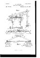
- FIG. 1 is a plan view; Fig. 2, the same with the top plate removed.
- Fig.3 shows a section through the line so of Fig. 1; Fig. 4, the same through line y y of Fig. 2, while Figs. to 11 show details of the apparatus.
- These levers are pivoted to the under side of the covering plate A and to the bottom plate 0 at B and B respectively, so as to be capable of being turned, and these levers are connected in pairs by bolts 13, sliding in the slits B in such a manner as to enable each pair to act like a pair of scissors, thus adjusting the level of the plate A according to the distance of their end points B.
- This simultaneous actuation from one point of all four levers is effected by means of a cog-wheel D, (shown in Fig.
- a ratchet-wheel d is attached to its axle cl between said cog-wheel and the covering-plate A, (see Fig.
- Each of them substantially consists of two side bars G2, which are covered by an ornamented plate G
- a sliding piece g which surrounds the toothed bar II, is attached by means of the bolt g, said piece serving at the same time as sliding guide for the said bar.
- a bar K there is also arranged between the side bars and engaging with the toothed bar II a bar K, (see Figs. 7 and 8,) which as the spring K acts upon the lever K is pressed against the toothed bar II, thereby insuring the relation of the whole pedal to that bar.
- the bar K On the plate A moving downward the bar K is freed from its engagement with the bar II by the projections I which are attached to the arms of the disengaging-bar F and which pass through plate A, pressing against the lever K thereby causing the latter to turn about pivot 7tand the bar K to disengage from the bar II.
- the bar II can in any suitable manner be secured to the pedal I of the piano; for instance, by means of the clamp L, as illustrated in Fig. 3, consisting substantially of two plates in closing the pedal I, the upper of which plates is suspended on the bar II, while the lower, by means of a screw L, presses the pedal I against the upper plate.
- the pedal attachment can be adjusted according to the size of any person without the least difficulty, its lowering to its lowest position being done automatically.
- An auxiliary pedal device consisting of a plate A supported by four levers B pivoted to a bottom plate 0, these levers crossing one another in pairs and connected by bolts sliding in slits, said. levers I being connected at their upper ends with toothed bars 15 actuated by a pinion D and hand-wheel D; pedal-bars pivoted to the upper side of the plate A and engaging toothed bars vertically pivoted to the pedals, substantially as set forth.
- An auxiliary pedal device consisting of. a plate A supported by four levers l3 pivoted to a bottom plate C, these levers crossing one another in pairs and connected by bolts sliding in slits, said levers I) being connected at their upper ends with toothed bars E parallel to one another guided on the lower side of plate A and actuated by one sole pinion l) and hand-wheel D, substantially as set forth.
- auxiliary pedal device in an auxiliary pedal device as described the two pedals G pivoted with the eyes (i to the upper side of a plate A, and with. the eyes 9 to a piece g surrounding a toothed shaft ll pivoted to the pedals; each of said pedals having, on its lower face a bar K catching with its ends into the teeth of shaft ll and held in this position by a lever K and a spring K the levers K being engaged with.
Description
3 SheetsSheet 1.
( No Mode 1.)
R. SCHULZE. PEDAL BOARD FOR PIANOS Patented Feb. 16, 189 7.
7 flarna 74/5 [messes 3 Sheets-Sheet 2.
(No Model.)
R. SGHULZE, PEDAL BOARD FOR PIANOS.
Patented Feb. 16, 1897.
1111/A will/111111110 -s mama- 1 y IIIIIIIIIIIIIIIM AIIM Jim M Wi/eswar:
firm? (No Model.) 3 Sheets-Sheet 3. R. SOHULZE. PEDAL BOARD FOR PIANOS.
No. 577,271. Patented Feb. 16, 1897.
UNITED STATES PATENT OFFICE.
REINHARD SCHULZE, OF BALTIMORE, MARYLAND.
PEDAL-BOARD FOR PIANOS.
SPECIFICATION forming part of Letters Patent No. 577,271, dated February 16, 1897.
Application fi e May 4, 1895. Serial No. 548,170. (No modeLl To all whom, it may concern:
Be it known that I, REINHARD SCI-IULZE, a resident of Baltimore, State of Maryland, have invented certain new and useful Improvements in Pedal-Boards for Pianos, of which the following is a specification.
The object of this invention is to provide means for facilitating the use of the pedals by small persons, especially children. This object was heretofore reached by providing two plates or blocks to be screwed onto the top of the pedals, it being necessary to preserve the height of the seat-that is to say, to leave the latter under all circumstances proportionate in height to the keyboard. These arrangements, however, did not fully answer the purpose, particularly as it was impracticable, if not impossible, to regulate the plates in question according to the size of the persons playing the instrument. As in order to obtain an easy play it is veryimportant that the pedals may be easily adjusted, and especially as nowadays children from early childhood are given the opportunity of learning to play the piano, it is essential to provide means for adjusting the above-described arrangement so as to correspond to the size of all persons. This point has been provided for in this invention by a pedal-board which can be adjusted by a simple touch with the hand.
This new apparatus is represented in the annexed drawings, in which Figure 1 is a plan view; Fig. 2, the same with the top plate removed. Fig.3 shows a section through the line so of Fig. 1; Fig. 4, the same through line y y of Fig. 2, while Figs. to 11 show details of the apparatus.
A flat box, open at the under side, which consists of a covering-plate A, surrounded by four side boards A, partly oblique to the plane of said plate, is supported by four levers B. These levers are pivoted to the under side of the covering plate A and to the bottom plate 0 at B and B respectively, so as to be capable of being turned, and these levers are connected in pairs by bolts 13, sliding in the slits B in such a manner as to enable each pair to act like a pair of scissors, thus adjusting the level of the plate A according to the distance of their end points B. This simultaneous actuation from one point of all four levers is effected by means of a cog-wheel D, (shown in Fig. 6 in a greater scale,) acted upon by the hand-wheel D above the covering-plate A and gearing with two parallel toothed bars E, which, when said cog-wheel turns, are moved in their longitudinal direction, and as they are inserted at E into the cross-bars E which latter support the points B, they cause the levers to approach or move from each other, according as the wheel D is turned to the right or to the left. The cross-bar E is shown in Fig. 5 in greater scale in front view and cross-section in connection with the levers B. To prevent an automatic undesirable turning of the cogwheel D, a ratchet-wheel d is attached to its axle cl between said cog-wheel and the covering-plate A, (see Fig. 6,) in which ratchetwheel engages a latch d", the turning-point d of which is on plate A. This latch, which is pressed against the ratchet-wheel by means of a spring, allows of the hand-wheel being turned only to the right-that is to say, so that the points 13 approach each other-thus raising the covering-plate A accordingly. Its lowering is effected by means of the disengaging-bar F, (shown in greater scale in Figs. 9 and 10 in plan view and cross-section,) which lies between the toothed bars E and the covering-plate A in such a manner that in turning from above with the aid of handle 6 the disk e to the right it presses the bolt E against the latch d thereby freeing the latter from engagement. The dead-weight of the plate A and of the attachments, to be afterward described, results in the cross-bars E and consequently the points B, being moved from each other and the device lowered. It remains to be explained that said cross-bars E slide on two strips 6 attached to the under side of the covering-plate A, also that the toothed bars E slide through cramps 2', which are likewise attached to plate A. On said plate A two pedals, which may be turned about the fulcra G, are arranged, and these engagin g with the toothed bars H are thus connected with the pedals of the pianoforte. Their construction may be understood from Figs. 1 and 3; furthermore, by Figs. 7 and 8, representing the single parts in greater scale. Each of them substantially consists of two side bars G2, which are covered by an ornamented plate G At the extreme end of the bars G2 a sliding piece g, which surrounds the toothed bar II, is attached by means of the bolt g, said piece serving at the same time as sliding guide for the said bar. As illustrated in Figs. 1 and 3, there is also arranged between the side bars and engaging with the toothed bar II a bar K, (see Figs. 7 and 8,) which as the spring K acts upon the lever K is pressed against the toothed bar II, thereby insuring the relation of the whole pedal to that bar. On the plate A moving downward the bar K is freed from its engagement with the bar II by the projections I which are attached to the arms of the disengaging-bar F and which pass through plate A, pressing against the lever K thereby causing the latter to turn about pivot 7tand the bar K to disengage from the bar II. The bar II can in any suitable manner be secured to the pedal I of the piano; for instance, by means of the clamp L, as illustrated in Fig. 3, consisting substantially of two plates in closing the pedal I, the upper of which plates is suspended on the bar II, while the lower, by means of a screw L, presses the pedal I against the upper plate.
As will be understood from the above description, the pedal attachment can be adjusted according to the size of any person without the least difficulty, its lowering to its lowest position being done automatically.
Having now particularly described and ascertained the nature of said invention, what I claim is 1. An auxiliary pedal device consisting of a plate A supported by four levers B pivoted to a bottom plate 0, these levers crossing one another in pairs and connected by bolts sliding in slits, said. levers I being connected at their upper ends with toothed bars 15 actuated by a pinion D and hand-wheel D; pedal-bars pivoted to the upper side of the plate A and engaging toothed bars vertically pivoted to the pedals, substantially as set forth.
2. An auxiliary pedal device consisting of. a plate A supported by four levers l3 pivoted to a bottom plate C, these levers crossing one another in pairs and connected by bolts sliding in slits, said levers I) being connected at their upper ends with toothed bars E parallel to one another guided on the lower side of plate A and actuated by one sole pinion l) and hand-wheel D, substantially as set forth.
In an auxiliary pedal device as described the two pedals G pivoted with the eyes (i to the upper side of a plate A, and with. the eyes 9 to a piece g surrounding a toothed shaft ll pivoted to the pedals; each of said pedals having, on its lower face a bar K catching with its ends into the teeth of shaft ll and held in this position by a lever K and a spring K the levers K being engaged with. the ends of a U shaped bar I on the lower side of the plate A and an eccentric disk 0 having a handle a On the top of its axle, substantially as set forth.
In testimony that I claim the foregoing as my invention I have signed my name in pres ence of two subscribing witnesses.
KIJINITARD SGIIULZE.
Witnesses JOHN S. Gnnn, CHARLES J'. Innrz.
Publications (1)
| Publication Number | Publication Date |
|---|---|
| US577271A true US577271A (en) | 1897-02-16 |
Family
ID=2645961
Family Applications (1)
| Application Number | Title | Priority Date | Filing Date |
|---|---|---|---|
| US577271D Expired - Lifetime US577271A (en) | Pedal-board for pianos |
Country Status (1)
| Country | Link |
|---|---|
| US (1) | US577271A (en) |
Cited By (1)
| Publication number | Priority date | Publication date | Assignee | Title |
|---|---|---|---|---|
| US11191544B2 (en) | 2011-10-19 | 2021-12-07 | Ethicon Endo-Surgery, Inc. | Clip applier adapted for use with a surgical robot |
-
0
- US US577271D patent/US577271A/en not_active Expired - Lifetime
Cited By (1)
| Publication number | Priority date | Publication date | Assignee | Title |
|---|---|---|---|---|
| US11191544B2 (en) | 2011-10-19 | 2021-12-07 | Ethicon Endo-Surgery, Inc. | Clip applier adapted for use with a surgical robot |
Similar Documents
| Publication | Publication Date | Title |
|---|---|---|
| US577271A (en) | Pedal-board for pianos | |
| DE3728841A1 (en) | Device for adjusting the key action of a keyboard | |
| US1125047A (en) | Adjusting device for musical instruments. | |
| US589658A (en) | Attachment for stringed musical instruments | |
| US442166A (en) | Francis bryan boyes | |
| US1060215A (en) | Cabinet. | |
| US71427A (en) | Island | |
| DE361836C (en) | Memory apparatus | |
| US974638A (en) | Incubator-alarm. | |
| US653731A (en) | Music-leaf turner. | |
| US451667A (en) | Musical instrument | |
| DE137603C (en) | ||
| US405465A (en) | Touch-regulator for pianos | |
| US954043A (en) | Pedal-action. | |
| US818555A (en) | Mechanical toy. | |
| US634995A (en) | Apparatus for turning over leaves of music. | |
| US589644A (en) | dernell | |
| DE466481C (en) | Mechanics for accordions | |
| DE1780C (en) | Sounding piano pedal | |
| US290163A (en) | William winter | |
| US787825A (en) | Finger-exerciser for students of type-writing. | |
| US847498A (en) | Auxiliary piano-pedal. | |
| US356803A (en) | William g | |
| US348629A (en) | Upright piano-forte | |
| DE40570C (en) | One-armed lever with adjusting weight, as a gymnastics device |