US5772239A - Airbag sub-module having fabric envelope with horn switch - Google Patents
Airbag sub-module having fabric envelope with horn switch Download PDFInfo
- Publication number
- US5772239A US5772239A US08/669,616 US66961696A US5772239A US 5772239 A US5772239 A US 5772239A US 66961696 A US66961696 A US 66961696A US 5772239 A US5772239 A US 5772239A
- Authority
- US
- United States
- Prior art keywords
- module
- sub
- air bag
- steering wheel
- inflator
- Prior art date
- Legal status (The legal status is an assumption and is not a legal conclusion. Google has not performed a legal analysis and makes no representation as to the accuracy of the status listed.)
- Expired - Fee Related
Links
Images


Classifications
-
- B—PERFORMING OPERATIONS; TRANSPORTING
- B60—VEHICLES IN GENERAL
- B60R—VEHICLES, VEHICLE FITTINGS, OR VEHICLE PARTS, NOT OTHERWISE PROVIDED FOR
- B60R21/00—Arrangements or fittings on vehicles for protecting or preventing injuries to occupants or pedestrians in case of accidents or other traffic risks
- B60R21/02—Occupant safety arrangements or fittings, e.g. crash pads
- B60R21/16—Inflatable occupant restraints or confinements designed to inflate upon impact or impending impact, e.g. air bags
- B60R21/20—Arrangements for storing inflatable members in their non-use or deflated condition; Arrangement or mounting of air bag modules or components
- B60R21/203—Arrangements for storing inflatable members in their non-use or deflated condition; Arrangement or mounting of air bag modules or components in steering wheels or steering columns
-
- B—PERFORMING OPERATIONS; TRANSPORTING
- B60—VEHICLES IN GENERAL
- B60Q—ARRANGEMENT OF SIGNALLING OR LIGHTING DEVICES, THE MOUNTING OR SUPPORTING THEREOF OR CIRCUITS THEREFOR, FOR VEHICLES IN GENERAL
- B60Q5/00—Arrangement or adaptation of acoustic signal devices
- B60Q5/001—Switches therefor
- B60Q5/003—Switches therefor mounted on the steering wheel
-
- B—PERFORMING OPERATIONS; TRANSPORTING
- B60—VEHICLES IN GENERAL
- B60R—VEHICLES, VEHICLE FITTINGS, OR VEHICLE PARTS, NOT OTHERWISE PROVIDED FOR
- B60R21/00—Arrangements or fittings on vehicles for protecting or preventing injuries to occupants or pedestrians in case of accidents or other traffic risks
- B60R21/02—Occupant safety arrangements or fittings, e.g. crash pads
- B60R21/16—Inflatable occupant restraints or confinements designed to inflate upon impact or impending impact, e.g. air bags
- B60R21/20—Arrangements for storing inflatable members in their non-use or deflated condition; Arrangement or mounting of air bag modules or components
- B60R21/201—Packaging straps or envelopes for inflatable members
Definitions
- the present invention relates to inflatable restraint systems for providing impact protection for the occupants of a motor vehicle. More particularly, the present invention relates to a supplemental restraint sub-module for integrated use with a vehicle steering wheel.
- Inflatable restraint systems are now commonly utilized for impact protection as supplemental restraints which are generally intended to be used with belt restraint systems.
- Driver air bag restraint systems are typically mounted on vehicle steering wheels, and inflate during a collision in response to an electrical signal generated from one or more crash sensors mounted to the motor vehicle.
- the inflated air bag provides energy absorption for an occupant during a vehicle impact. Additionally, the air bag improves the contact surface for the occupant with the vehicle interior during a frontal crash.
- a typical air bag module consists of the following parts: a housing structure, an air bag, an inflator, a triggering mechanism, and fasteners.
- the housing provides a structure for mounting the air bag to the air bag module and a mounting surface to attach the module to the vehicle steering wheel, as well as provides reaction surfaces configured to control and direct the air bag during inflation.
- the inflator is usually either a stored gas or solid propellant device which provides the fluid for the rapid filling of the air bag.
- current modules typically use a number of fasteners to attach the module components and to attach the module to the vehicle structure.
- modules designed to be integrated into vehicle steering wheels Since the module is generally integrated into a central hub of the vehicle steering wheel, its size must be minimized in order not to obstruct the vehicle operator's view of the vehicle instrument panel.
- modules designed to be integrated into a vehicle steering wheel provide additional challenges such as incorporating the vehicle horn switch into the module design and allowing room on the steering wheel for additional accessory switches such as turn signals, light controls, wiper controls, etc.
- efforts to achieve benefits in these areas must not sacrifice the performance of the restraint system.
- the sub-module of the present invention includes an air bag and an inflator enclosed in a fabric envelope.
- a primary object of the present invention is to provide an improved supplemental restraint sub-module design which is smaller, lighter, and has fewer parts than prior art sub-modules. These advantages make the sub-module easier and faster to assemble and more cost effective to produce. Furthermore, the improved sub-module allows for greater visibility of the vehicle instruments by the vehicle operator as well as additional space on or near the steering wheel for accessory switches.
- the improvements provided by the present invention are achieved through an efficient integration of components and functions of the sub-module and vehicle steering wheel.
- the sub-module of the present invention is configured to be installed in a well formed in the central hub of a vehicle steering wheel and is designed to use the well side walls as reaction surfaces during air bag deployment.
- the sub-module is configured as a "drop-in" sub-assembly which is easily mounted in place. With this configuration, the module housing required in traditional steering wheel inflatable restraint system can be eliminated. Furthermore, the resulting lighter steering wheel reduces the moment of inertia of the steering wheel which can provide improved handling response.
- a membrane horn switch can also be incorporated into the sub-module of this invention.
- the membrane horn switch may be sewn into the fabric envelope along with a back plate.
- the switch can be positioned beneath the steering wheel cover and can be configured to deform when pressure is applied to the steering wheel cover.
- the back plate can be positioned between the membrane horn switch and the air bag and to provide a flat backing surface for the membrane horn switch.
- the fabric envelope includes a slot cut into the fabric including a series of tear tabs which are configured to tear during air bag deployment allowing the air bag to expand outside of the sub-module.
- a tear seam is included comprising a weak stitch pattern of thin thread which is configured to pull apart and release the air bag upon deployment.
- the inflator is designed with an integral round flange surrounding the inflator which is used for mounting the sub-module onto the mounting plate of the steering wheel.
- the flange can have bolts staked to it which can extend through holes in the mounting plate to be secured by nuts to the mounting plate.
- the inflator can be inserted into the air bag, the air bag can be folded and the fabric envelope can be wrapped around the folded air bag. The air bag and envelope are trapped in place between the inflator flange and mounting plate when the sub-module is installed into the steering wheel.
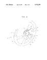
- FIG. 1 is a pictorial view of a steering wheel and the sub-module of the present invention
- FIG. 2 is a partial cross-sectional view of the sub-module of the present invention installed in a vehicle steering wheel;
- FIG. 3 is a pictorial view of an assembled sub-module of the present invention, illustrating the sub-module mounting means
- FIG. 4 is a cross-sectional view of the sub-module taken along line 4--4 of FIG. 3;
- FIG. 5 is a pictorial view of a first embodiment of the assembled sub-module of the present invention, illustrating the fabric envelope tear tabs;
- FIG. 6 is a pictorial view of a second embodiment of the assembled sub-module of the present invention, illustrating the envelope tear seam.
- the supplemental restraint sub-module is configured for integrated use with a vehicle steering wheel assembly 12, having an aesthetic urethane molded cover 14 which is molded over armature 13.
- the steering wheel assembly 12 forms a molded well 16 within the central hub portion 18 of the steering wheel assembly.
- the cover 14 also includes tear seams 15 which are configured to rupture and open upon air bag deployment, allowing the air bag 34 to inflate outside of the steering wheel assembly 12.
- the cover 14 is designed to remain attached to the steering wheel assembly 12 during air bag deployment.
- the sub-module 10 is placed inside the molded well 16 and is held in place by a mounting plate 20.
- the sub-module 10 is secured to the mounting plate 20 by three threaded bolts 22 extending from the sub-module 10, through holes 24 in the mounting plate 20.
- the bolts 22 engage threaded nuts 26 on the back side of the mounting plate 20.
- the mounting plate 20 is secured to the steering wheel assembly 12 by screws 28 inserted through the mounting plate 20 into the cover 14 and steering wheel 12.
- a steering shaft 30 having a splined end is accepted into the mounting plate hole 31 to secure the steering wheel/sub-module assembly to the vehicle. It is contemplated that other fasteners, such as rivets, ball locks, etc., could be used for securing the parts as well as adhesive bonding or post-assembly forming operations to interlock the parts together.
- the supplemental restraint sub-module 10 comprises an inflator 32, an air bag 34, and a fabric envelope 36.
- the inflator 32 is configured for receiving a crash signal from a crash sensor (not shown) and for generating inflation gas in response to the crash signal.
- the inflator 32 includes an integral round flange 38 to which bolts 22 are staked. It is contemplated that the inflator 32 can be a stored gas, solid propellant or hybrid type inflator.
- the air bag 34 includes a mouth opening into which the inflator 32 is placed when the sub-module 10 is assembled. During assembly, the air bag 34 is folded and the fabric envelope 36 is wrapped around the air bag/inflator assembly to hold the sub-module 10 together.
- the fabric envelope 36 comprises a sheet of material folded over and sewn together by sewn seams 44 along the outside edges of the envelope 36 to form an elongated pocket sleeve.
- the fabric envelope 36 can be made from two or more separate sheets of material sewn together to form an elongated pocket sleeve.
- Tear tabs 40 are included in a slot 42 on the envelope 36 to hold the envelope 36 together.
- the tear tabs 40 are only strong enough to retain the folded air bag 34.
- the slot 42 and tear tabs 40 are replaced with a tear seam 46.
- the tear seam 46 comprises a weak stitch pattern of thin thread which is configured to pull apart and release the air bag 34 as the air bag 34 is inflated by gases from the inflator 32.
- mounting plate 20 and steering wheel assembly well 16 combine to act as reaction surfaces which cause the bag to deploy properly.
- a membrane horn switch 48 can be integrated into the sub-module 10, by sewing the switch 48 into the pocket sleeve of the envelope 36.
- the switch 48 is positioned between the layers of fabric in the envelope 36 and sewn into place so that when the sub-module 10 is assembled into the well 16 the horn switch 48 is located beneath the steering wheel cover 14. When the cover 14 is pressed, the horn switch 48 is deformed allowing current to flow through wires 50 exiting the sub-module 10 to the vehicle horn (not shown).
- a backing plate 52 can be included between the horn switch 48 and the air bag 34 to provide a flat backing surface for the horn switch 48.
Landscapes
- Engineering & Computer Science (AREA)
- Mechanical Engineering (AREA)
- Physics & Mathematics (AREA)
- Acoustics & Sound (AREA)
- Air Bags (AREA)
Abstract
Description
Claims (9)
Priority Applications (3)
| Application Number | Priority Date | Filing Date | Title |
|---|---|---|---|
| US08/669,616 US5772239A (en) | 1996-06-24 | 1996-06-24 | Airbag sub-module having fabric envelope with horn switch |
| DE19724170A DE19724170A1 (en) | 1996-06-24 | 1997-06-06 | Airbag system for motor vehicle steering wheel module |
| JP16618097A JP3223245B2 (en) | 1996-06-24 | 1997-06-23 | Cushion submodule and inflator for integrated restraint system |
Applications Claiming Priority (1)
| Application Number | Priority Date | Filing Date | Title |
|---|---|---|---|
| US08/669,616 US5772239A (en) | 1996-06-24 | 1996-06-24 | Airbag sub-module having fabric envelope with horn switch |
Publications (1)
| Publication Number | Publication Date |
|---|---|
| US5772239A true US5772239A (en) | 1998-06-30 |
Family
ID=24687020
Family Applications (1)
| Application Number | Title | Priority Date | Filing Date |
|---|---|---|---|
| US08/669,616 Expired - Fee Related US5772239A (en) | 1996-06-24 | 1996-06-24 | Airbag sub-module having fabric envelope with horn switch |
Country Status (3)
| Country | Link |
|---|---|
| US (1) | US5772239A (en) |
| JP (1) | JP3223245B2 (en) |
| DE (1) | DE19724170A1 (en) |
Cited By (36)
| Publication number | Priority date | Publication date | Assignee | Title |
|---|---|---|---|---|
| US6164690A (en) * | 1998-05-22 | 2000-12-26 | Breed Automotive Technology, Inc. | Steering wheel |
| US6176509B1 (en) * | 1997-07-08 | 2001-01-23 | Kabushiki Kaisha Tokai-Rika-Denki-Seisakusho | Air bag device and method for accommodating an air bag in the air bag device |
| US6250675B1 (en) * | 1996-05-28 | 2001-06-26 | Petri Ag | Airbag, method of folding the latter, and device for carrying out the method |
| US6623034B2 (en) | 1996-05-28 | 2003-09-23 | Takata-Petri Ag | Airbag having chaotic folds and airbag module with the same |
| US20030189319A1 (en) * | 2002-04-03 | 2003-10-09 | Quin Soderquist | Airbag cover deployment flaps |
| US6682093B2 (en) * | 2000-12-19 | 2004-01-27 | Toyoda Gosei Co., Ltd. | Air bag device |
| US20050104338A1 (en) * | 2003-11-19 | 2005-05-19 | Quin Soderquist | Applique film airbag cover |
| US7111867B2 (en) * | 2001-05-22 | 2006-09-26 | Trw Automotive Safety Systems Gmbh & Co. Kg | Airbag module and vehicle steering wheel comprising an airbag module |
| US20070138769A1 (en) * | 2005-12-21 | 2007-06-21 | Takata Corporation | Airbag apparatus |
| US20080217887A1 (en) * | 2007-03-06 | 2008-09-11 | Seymour Brian T | Airbag protection flap |
| US20090102173A1 (en) * | 2005-04-27 | 2009-04-23 | Autoliv Asp, Inc. | Airbag cushion folding methods |
| US20090108574A1 (en) * | 2005-04-27 | 2009-04-30 | Autoliv Asp, Inc. | Airbag cushion folding methods |
| US20090146401A1 (en) * | 2006-06-07 | 2009-06-11 | Takata-Petri Ag | Airbag device for a motor vehicle |
| US20090152842A1 (en) * | 2007-12-13 | 2009-06-18 | Autoliv Asp, Inc. | Airbag lateral flap |
| US20100270782A1 (en) * | 2009-04-27 | 2010-10-28 | Autoliv Asp, Inc. | Inflatable knee airbag assemblies with bag straps for wrapping the airbags and optimizing deployment |
| US20100270779A1 (en) * | 2009-04-27 | 2010-10-28 | Autoliv Asp, Inc. | Inflatable knee airbags and internal tethers produced from single panels of material |
| US7926844B2 (en) | 2008-04-10 | 2011-04-19 | Autoliv Asp, Inc. | Airbag assembly and method of packing |
| US20110088356A1 (en) * | 2009-10-16 | 2011-04-21 | Autoliv Asp, Inc. | Inflatable airbag cushions with deployment flaps and methods for folding |
| US20110101660A1 (en) * | 2009-11-03 | 2011-05-05 | Autoliv Asp, Inc. | Low-mount inflatable knee airbags having serial chambers |
| US20110148077A1 (en) * | 2009-12-22 | 2011-06-23 | Autoliv Asp, Inc. | Inflatable airbag assembly with an integral cover |
| US8083254B2 (en) | 2009-04-27 | 2011-12-27 | Autoliv Asp, Inc. | Knee airbag assemblies configured for inflator insertion and inflator-mediated coupling to an airbag housing |
| US8226118B2 (en) | 2009-08-05 | 2012-07-24 | Autoliv Asp, Inc. | Safety venting with passively closeable vents |
| US8297654B2 (en) | 2010-03-31 | 2012-10-30 | Takata Corporation | Airbag and airbag apparatus |
| US8297650B2 (en) | 2010-08-31 | 2012-10-30 | Autoliv Asp, Inc. | Inflatable knee airbag assemblies with articulating housings |
| US8297649B2 (en) | 2009-07-16 | 2012-10-30 | Autoliv Asp, Inc. | Inflatable knee airbag having two chambers separated by an internal tether |
| US8360464B2 (en) | 2010-08-31 | 2013-01-29 | Autoliv Asp, Inc. | Covers for inflatable knee airbag housings |
| US8500157B2 (en) | 2009-04-27 | 2013-08-06 | Autoliv Asp, Inc. | Knee airbag assemblies and related methods |
| US8505963B1 (en) | 2012-02-24 | 2013-08-13 | Autoliv Asp, Inc. | Airbag assemblies with strap clamps |
| US8540276B2 (en) | 2011-11-07 | 2013-09-24 | Autoliv Asp, Inc. | Inflatable knee airbag assemblies with cushion fold pattern |
| US8777262B2 (en) | 2009-04-27 | 2014-07-15 | Autoliv Asp, Inc. | Airbag assemblies with stabilizer straps |
| US9010804B2 (en) | 2013-03-15 | 2015-04-21 | Autoliv Asp, Inc. | Airbag assemblies with constrained stabilizer straps |
| US20180056915A1 (en) * | 2016-09-01 | 2018-03-01 | James Webber | Low mass passenger airbag |
| CN108698540A (en) * | 2015-12-04 | 2018-10-23 | 均胜安全系统收购有限责任公司 | Power senses horn system |
| US10696266B2 (en) | 2017-11-10 | 2020-06-30 | Autoliv Asp, Inc. | Inflatable knee airbag assemblies |
| US11518334B2 (en) | 2019-06-24 | 2022-12-06 | Joyson Safety Systems Acquisition Llc | Methods and systems for pre-fixing an airbag module during installation |
| US12447919B1 (en) * | 2024-08-28 | 2025-10-21 | GM Global Technology Operations LLC | Roof rail airbag assembly |
Families Citing this family (6)
| Publication number | Priority date | Publication date | Assignee | Title |
|---|---|---|---|---|
| DE19940360B4 (en) * | 1999-08-25 | 2005-12-15 | Autoliv Development Ab | Airbag with a reinforcing layer designed as a diffuser and cover |
| WO2002055345A1 (en) * | 2001-01-12 | 2002-07-18 | Toyo Tire & Rubber Co., Ltd. | Air bag device |
| DE102004023780B4 (en) * | 2004-05-07 | 2012-06-21 | Takata-Petri Ag | airbag device |
| JP5543491B2 (en) * | 2009-11-30 | 2014-07-09 | オートリブ ディベロップメント エービー | Airbag device |
| DE102013007734B4 (en) * | 2013-05-07 | 2016-09-22 | Autoliv Development Ab | Airbag module and airbag device |
| DE102024129686A1 (en) * | 2024-10-14 | 2026-04-16 | ZF Automotive Safety Germany GmbH | GASSACK MODULE AND PROCEDURE |
Citations (22)
| Publication number | Priority date | Publication date | Assignee | Title |
|---|---|---|---|---|
| US3714844A (en) * | 1970-01-27 | 1973-02-06 | Masakazu Inagaki | Steering wheel consisting of a light frame integrally moulding, processed from a flat plate |
| US3819205A (en) * | 1972-09-25 | 1974-06-25 | Gen Motors Corp | Modular occupant restraint system |
| US4148503A (en) * | 1976-03-26 | 1979-04-10 | Toyota Jidosha Kogyo Kabushiki Kaisha | Inflating type occupant restraint device |
| US4828286A (en) * | 1986-07-22 | 1989-05-09 | Trw Repa Gmbh | Gas cushion impact protection device for motor vehicles |
| JPH035257A (en) * | 1989-05-31 | 1991-01-11 | Nissan Motor Co Ltd | Air bag device |
| US4995638A (en) * | 1988-12-29 | 1991-02-26 | Toyota Jidosha Kabushiki Kaisha | Air bag cover |
| US5005860A (en) * | 1989-05-31 | 1991-04-09 | Kabushiki Kaisha Tokai-Rika-Denki-Seisakusho | Air bag assembly mounting mechanism |
| US5062664A (en) * | 1989-05-11 | 1991-11-05 | Allied-Signal Inc. | Air bag assembly |
| US5186490A (en) * | 1991-09-23 | 1993-02-16 | Morton International, Inc. | Driver cover integral horn switch with solid reinforcement structure |
| US5242192A (en) * | 1992-02-24 | 1993-09-07 | Morton International, Inc. | Fabric cover/chute for airbag modules |
| US5342086A (en) * | 1993-05-03 | 1994-08-30 | Morton International, Inc. | Closure for an inflatable restraint system |
| US5369232A (en) * | 1993-07-23 | 1994-11-29 | Morton International, Inc. | Driver side airbag module cover and horn switch |
| US5399819A (en) * | 1994-03-29 | 1995-03-21 | Morton International, Inc. | Airbag cover horn switch |
| US5423569A (en) * | 1991-07-08 | 1995-06-13 | United Technologies Automotive, Inc. | Electric signalling in a supplemental passenger restraint system |
| US5431437A (en) * | 1992-04-08 | 1995-07-11 | Davidson Textron Inc. | Horn actuator for a steering wheel with an air bag unit |
| US5449197A (en) * | 1992-09-04 | 1995-09-12 | Mercedes-Benz Ag | Air bag cover sewn to underlying membrane switch |
| US5452913A (en) * | 1993-08-31 | 1995-09-26 | Morton International, Inc. | Break-away airbag retaining flap |
| US5470099A (en) * | 1993-11-01 | 1995-11-28 | General Motors Corporation | One-piece steering wheel assembly |
| US5498030A (en) * | 1995-03-28 | 1996-03-12 | General Motors Corporation | Air bag module |
| US5562301A (en) * | 1993-04-26 | 1996-10-08 | Trw Repa Gmbh | Assembly for mounting an air bag cover and inflator to a steering wheel |
| US5584501A (en) * | 1995-09-15 | 1996-12-17 | Trw Inc. | Vehicle occupant restraint apparatus |
| US5626358A (en) * | 1996-01-11 | 1997-05-06 | Morton International, Inc. | Airbag cushion assembly with horn switch pocket |
Family Cites Families (1)
| Publication number | Priority date | Publication date | Assignee | Title |
|---|---|---|---|---|
| US5523532A (en) | 1995-02-06 | 1996-06-04 | Morton International, Inc. | Airbag module cover with attached horn switch and method of producing same |
-
1996
- 1996-06-24 US US08/669,616 patent/US5772239A/en not_active Expired - Fee Related
-
1997
- 1997-06-06 DE DE19724170A patent/DE19724170A1/en not_active Ceased
- 1997-06-23 JP JP16618097A patent/JP3223245B2/en not_active Expired - Fee Related
Patent Citations (22)
| Publication number | Priority date | Publication date | Assignee | Title |
|---|---|---|---|---|
| US3714844A (en) * | 1970-01-27 | 1973-02-06 | Masakazu Inagaki | Steering wheel consisting of a light frame integrally moulding, processed from a flat plate |
| US3819205A (en) * | 1972-09-25 | 1974-06-25 | Gen Motors Corp | Modular occupant restraint system |
| US4148503A (en) * | 1976-03-26 | 1979-04-10 | Toyota Jidosha Kogyo Kabushiki Kaisha | Inflating type occupant restraint device |
| US4828286A (en) * | 1986-07-22 | 1989-05-09 | Trw Repa Gmbh | Gas cushion impact protection device for motor vehicles |
| US4995638A (en) * | 1988-12-29 | 1991-02-26 | Toyota Jidosha Kabushiki Kaisha | Air bag cover |
| US5062664A (en) * | 1989-05-11 | 1991-11-05 | Allied-Signal Inc. | Air bag assembly |
| JPH035257A (en) * | 1989-05-31 | 1991-01-11 | Nissan Motor Co Ltd | Air bag device |
| US5005860A (en) * | 1989-05-31 | 1991-04-09 | Kabushiki Kaisha Tokai-Rika-Denki-Seisakusho | Air bag assembly mounting mechanism |
| US5423569A (en) * | 1991-07-08 | 1995-06-13 | United Technologies Automotive, Inc. | Electric signalling in a supplemental passenger restraint system |
| US5186490A (en) * | 1991-09-23 | 1993-02-16 | Morton International, Inc. | Driver cover integral horn switch with solid reinforcement structure |
| US5242192A (en) * | 1992-02-24 | 1993-09-07 | Morton International, Inc. | Fabric cover/chute for airbag modules |
| US5431437A (en) * | 1992-04-08 | 1995-07-11 | Davidson Textron Inc. | Horn actuator for a steering wheel with an air bag unit |
| US5449197A (en) * | 1992-09-04 | 1995-09-12 | Mercedes-Benz Ag | Air bag cover sewn to underlying membrane switch |
| US5562301A (en) * | 1993-04-26 | 1996-10-08 | Trw Repa Gmbh | Assembly for mounting an air bag cover and inflator to a steering wheel |
| US5342086A (en) * | 1993-05-03 | 1994-08-30 | Morton International, Inc. | Closure for an inflatable restraint system |
| US5369232A (en) * | 1993-07-23 | 1994-11-29 | Morton International, Inc. | Driver side airbag module cover and horn switch |
| US5452913A (en) * | 1993-08-31 | 1995-09-26 | Morton International, Inc. | Break-away airbag retaining flap |
| US5470099A (en) * | 1993-11-01 | 1995-11-28 | General Motors Corporation | One-piece steering wheel assembly |
| US5399819A (en) * | 1994-03-29 | 1995-03-21 | Morton International, Inc. | Airbag cover horn switch |
| US5498030A (en) * | 1995-03-28 | 1996-03-12 | General Motors Corporation | Air bag module |
| US5584501A (en) * | 1995-09-15 | 1996-12-17 | Trw Inc. | Vehicle occupant restraint apparatus |
| US5626358A (en) * | 1996-01-11 | 1997-05-06 | Morton International, Inc. | Airbag cushion assembly with horn switch pocket |
Cited By (50)
| Publication number | Priority date | Publication date | Assignee | Title |
|---|---|---|---|---|
| US6250675B1 (en) * | 1996-05-28 | 2001-06-26 | Petri Ag | Airbag, method of folding the latter, and device for carrying out the method |
| US6623034B2 (en) | 1996-05-28 | 2003-09-23 | Takata-Petri Ag | Airbag having chaotic folds and airbag module with the same |
| US6176509B1 (en) * | 1997-07-08 | 2001-01-23 | Kabushiki Kaisha Tokai-Rika-Denki-Seisakusho | Air bag device and method for accommodating an air bag in the air bag device |
| US6164690A (en) * | 1998-05-22 | 2000-12-26 | Breed Automotive Technology, Inc. | Steering wheel |
| US6682093B2 (en) * | 2000-12-19 | 2004-01-27 | Toyoda Gosei Co., Ltd. | Air bag device |
| US7111867B2 (en) * | 2001-05-22 | 2006-09-26 | Trw Automotive Safety Systems Gmbh & Co. Kg | Airbag module and vehicle steering wheel comprising an airbag module |
| US20030189319A1 (en) * | 2002-04-03 | 2003-10-09 | Quin Soderquist | Airbag cover deployment flaps |
| US6874810B2 (en) | 2002-04-03 | 2005-04-05 | Autoliv Asp. Inc. | Airbag cover deployment flaps |
| US20050104338A1 (en) * | 2003-11-19 | 2005-05-19 | Quin Soderquist | Applique film airbag cover |
| US20090102173A1 (en) * | 2005-04-27 | 2009-04-23 | Autoliv Asp, Inc. | Airbag cushion folding methods |
| US20090108574A1 (en) * | 2005-04-27 | 2009-04-30 | Autoliv Asp, Inc. | Airbag cushion folding methods |
| US7845682B2 (en) | 2005-04-27 | 2010-12-07 | Autoliv Asp, Inc. | Airbag cushion folding methods |
| US7942442B2 (en) | 2005-04-27 | 2011-05-17 | Autoliv Asp, Inc. | Airbag cushion folding methods |
| US20070138769A1 (en) * | 2005-12-21 | 2007-06-21 | Takata Corporation | Airbag apparatus |
| US7597343B2 (en) * | 2005-12-21 | 2009-10-06 | Takata Corporation | Airbag apparatus |
| US20090146401A1 (en) * | 2006-06-07 | 2009-06-11 | Takata-Petri Ag | Airbag device for a motor vehicle |
| US7874580B2 (en) | 2006-06-07 | 2011-01-25 | Takata-Petri Ag | Airbag device for a motor vehicle |
| US20080217887A1 (en) * | 2007-03-06 | 2008-09-11 | Seymour Brian T | Airbag protection flap |
| US7770925B2 (en) * | 2007-03-06 | 2010-08-10 | Autoliv Asp, Inc. | Airbag protection flap |
| US20090152842A1 (en) * | 2007-12-13 | 2009-06-18 | Autoliv Asp, Inc. | Airbag lateral flap |
| US8272664B2 (en) | 2007-12-13 | 2012-09-25 | Autoliv Asp, Inc. | Airbag lateral flap |
| US7926844B2 (en) | 2008-04-10 | 2011-04-19 | Autoliv Asp, Inc. | Airbag assembly and method of packing |
| US20100270779A1 (en) * | 2009-04-27 | 2010-10-28 | Autoliv Asp, Inc. | Inflatable knee airbags and internal tethers produced from single panels of material |
| US8777262B2 (en) | 2009-04-27 | 2014-07-15 | Autoliv Asp, Inc. | Airbag assemblies with stabilizer straps |
| US8500157B2 (en) | 2009-04-27 | 2013-08-06 | Autoliv Asp, Inc. | Knee airbag assemblies and related methods |
| US20100270782A1 (en) * | 2009-04-27 | 2010-10-28 | Autoliv Asp, Inc. | Inflatable knee airbag assemblies with bag straps for wrapping the airbags and optimizing deployment |
| US8083254B2 (en) | 2009-04-27 | 2011-12-27 | Autoliv Asp, Inc. | Knee airbag assemblies configured for inflator insertion and inflator-mediated coupling to an airbag housing |
| US8118325B2 (en) | 2009-04-27 | 2012-02-21 | Autoliv Asp, Inc. | Inflatable knee airbags and internal tethers produced from single panels of material |
| US8297649B2 (en) | 2009-07-16 | 2012-10-30 | Autoliv Asp, Inc. | Inflatable knee airbag having two chambers separated by an internal tether |
| US8226118B2 (en) | 2009-08-05 | 2012-07-24 | Autoliv Asp, Inc. | Safety venting with passively closeable vents |
| US8407968B2 (en) | 2009-10-16 | 2013-04-02 | Autoliv Asp, Inc. | Method of packaging an inflatable airbag cushion including a wrapper and deployment flap |
| US20110088356A1 (en) * | 2009-10-16 | 2011-04-21 | Autoliv Asp, Inc. | Inflatable airbag cushions with deployment flaps and methods for folding |
| US8272667B2 (en) | 2009-11-03 | 2012-09-25 | Autoliv Asp, Inc. | Low-mount inflatable knee airbags having serial chambers |
| US20110101660A1 (en) * | 2009-11-03 | 2011-05-05 | Autoliv Asp, Inc. | Low-mount inflatable knee airbags having serial chambers |
| US20110148077A1 (en) * | 2009-12-22 | 2011-06-23 | Autoliv Asp, Inc. | Inflatable airbag assembly with an integral cover |
| US8500155B2 (en) | 2009-12-22 | 2013-08-06 | Autoliv Asp, Inc. | Inflatable airbag assembly with an integral cover |
| US8297654B2 (en) | 2010-03-31 | 2012-10-30 | Takata Corporation | Airbag and airbag apparatus |
| US8297650B2 (en) | 2010-08-31 | 2012-10-30 | Autoliv Asp, Inc. | Inflatable knee airbag assemblies with articulating housings |
| US8360464B2 (en) | 2010-08-31 | 2013-01-29 | Autoliv Asp, Inc. | Covers for inflatable knee airbag housings |
| US8540276B2 (en) | 2011-11-07 | 2013-09-24 | Autoliv Asp, Inc. | Inflatable knee airbag assemblies with cushion fold pattern |
| US8505963B1 (en) | 2012-02-24 | 2013-08-13 | Autoliv Asp, Inc. | Airbag assemblies with strap clamps |
| US9010804B2 (en) | 2013-03-15 | 2015-04-21 | Autoliv Asp, Inc. | Airbag assemblies with constrained stabilizer straps |
| CN108698540A (en) * | 2015-12-04 | 2018-10-23 | 均胜安全系统收购有限责任公司 | Power senses horn system |
| CN108698540B (en) * | 2015-12-04 | 2022-03-01 | 均胜安全系统收购有限责任公司 | Force sensing horn system |
| US11590889B2 (en) | 2015-12-04 | 2023-02-28 | Joyson Safety Systems Acquisition Llc | Force sensing horn system |
| US20180056915A1 (en) * | 2016-09-01 | 2018-03-01 | James Webber | Low mass passenger airbag |
| US10112568B2 (en) * | 2016-09-01 | 2018-10-30 | Fca Us Llc | Low mass passenger airbag |
| US10696266B2 (en) | 2017-11-10 | 2020-06-30 | Autoliv Asp, Inc. | Inflatable knee airbag assemblies |
| US11518334B2 (en) | 2019-06-24 | 2022-12-06 | Joyson Safety Systems Acquisition Llc | Methods and systems for pre-fixing an airbag module during installation |
| US12447919B1 (en) * | 2024-08-28 | 2025-10-21 | GM Global Technology Operations LLC | Roof rail airbag assembly |
Also Published As
| Publication number | Publication date |
|---|---|
| DE19724170A1 (en) | 1998-01-08 |
| JPH1067290A (en) | 1998-03-10 |
| JP3223245B2 (en) | 2001-10-29 |
Similar Documents
| Publication | Publication Date | Title |
|---|---|---|
| US5772239A (en) | Airbag sub-module having fabric envelope with horn switch | |
| US5564739A (en) | Side impact airbag module with soft cover | |
| EP0061828B1 (en) | Low mount, easily assembled, air bag passive restraint module | |
| EP0546655B1 (en) | Aspirated air cushion restraint system | |
| US6099027A (en) | Decorative emblem for air bag module cover | |
| US6135489A (en) | Tear seam for air bag module cover | |
| US5605347A (en) | Airbag module with simplified cushion attachment | |
| EP0810128A2 (en) | Roof-mounted air bag | |
| JP3440823B2 (en) | Airbag device | |
| JP3025760U (en) | Cylindrical airbag module structure and airbag composite mechanism including the same | |
| US5226670A (en) | Vehicle safety apparatus | |
| JPH09164894A (en) | Expansible constraint module | |
| JPH08230596A (en) | Air bag arrester for fellow passenger | |
| JPH04185551A (en) | Air bag cover for automobile | |
| US5441299A (en) | Air bag inflator subassembly for installation onto the dashboard substrate of a motor vehicle | |
| US5419583A (en) | Air bag device for an automotive vehicle | |
| JPH02155855A (en) | Air bag case | |
| US5738366A (en) | Chute structure for an inflatable vehicle occupant restraint | |
| US6371514B1 (en) | Air bag module mounted in vehicle door | |
| US6517105B1 (en) | Steering wheel assembly featuring the elimination of a contact coil | |
| US5947512A (en) | Tethered horn switch for air bag module | |
| US6164684A (en) | Fastening structure for interconnecting parts of a vehicle occupant protection apparatus | |
| JP4653885B2 (en) | Airbag device | |
| US6010148A (en) | Air bag cover with membrane type horn switch | |
| US7118128B2 (en) | Low leakage airbag module |
Legal Events
| Date | Code | Title | Description |
|---|---|---|---|
| AS | Assignment |
Owner name: TAKATA, INC., MICHIGAN Free format text: ASSIGNMENT OF ASSIGNORS INTEREST;ASSIGNOR:SEYMOUR, BRIAN T,;REEL/FRAME:008330/0117 Effective date: 19960618 |
|
| FPAY | Fee payment |
Year of fee payment: 4 |
|
| FEPP | Fee payment procedure |
Free format text: PAYER NUMBER DE-ASSIGNED (ORIGINAL EVENT CODE: RMPN); ENTITY STATUS OF PATENT OWNER: LARGE ENTITY Free format text: PAYOR NUMBER ASSIGNED (ORIGINAL EVENT CODE: ASPN); ENTITY STATUS OF PATENT OWNER: LARGE ENTITY |
|
| REMI | Maintenance fee reminder mailed | ||
| FPAY | Fee payment |
Year of fee payment: 8 |
|
| SULP | Surcharge for late payment |
Year of fee payment: 7 |
|
| REMI | Maintenance fee reminder mailed | ||
| LAPS | Lapse for failure to pay maintenance fees | ||
| STCH | Information on status: patent discontinuation |
Free format text: PATENT EXPIRED DUE TO NONPAYMENT OF MAINTENANCE FEES UNDER 37 CFR 1.362 |
|
| FP | Lapsed due to failure to pay maintenance fee |
Effective date: 20100630 |