US5769624A - Variable flame burner configuration - Google Patents
Variable flame burner configuration Download PDFInfo
- Publication number
- US5769624A US5769624A US08/403,706 US40370695A US5769624A US 5769624 A US5769624 A US 5769624A US 40370695 A US40370695 A US 40370695A US 5769624 A US5769624 A US 5769624A
- Authority
- US
- United States
- Prior art keywords
- nozzle
- nozzles
- burner
- flame
- fuel
- Prior art date
- Legal status (The legal status is an assumption and is not a legal conclusion. Google has not performed a legal analysis and makes no representation as to the accuracy of the status listed.)
- Expired - Lifetime
Links
Images


Classifications
-
- F—MECHANICAL ENGINEERING; LIGHTING; HEATING; WEAPONS; BLASTING
- F27—FURNACES; KILNS; OVENS; RETORTS
- F27D—DETAILS OR ACCESSORIES OF FURNACES, KILNS, OVENS OR RETORTS, IN SO FAR AS THEY ARE OF KINDS OCCURRING IN MORE THAN ONE KIND OF FURNACE
- F27D99/00—Subject matter not provided for in other groups of this subclass
- F27D99/0001—Heating elements or systems
- F27D99/0033—Heating elements or systems using burners
-
- F—MECHANICAL ENGINEERING; LIGHTING; HEATING; WEAPONS; BLASTING
- F23—COMBUSTION APPARATUS; COMBUSTION PROCESSES
- F23D—BURNERS
- F23D14/00—Burners for combustion of a gas, e.g. of a gas stored under pressure as a liquid
- F23D14/20—Non-premix gas burners, i.e. in which gaseous fuel is mixed with combustion air on arrival at the combustion zone
-
- F—MECHANICAL ENGINEERING; LIGHTING; HEATING; WEAPONS; BLASTING
- F23—COMBUSTION APPARATUS; COMBUSTION PROCESSES
- F23D—BURNERS
- F23D14/00—Burners for combustion of a gas, e.g. of a gas stored under pressure as a liquid
- F23D14/46—Details
- F23D14/48—Nozzles
-
- F—MECHANICAL ENGINEERING; LIGHTING; HEATING; WEAPONS; BLASTING
- F23—COMBUSTION APPARATUS; COMBUSTION PROCESSES
- F23D—BURNERS
- F23D23/00—Assemblies of two or more burners
-
- F—MECHANICAL ENGINEERING; LIGHTING; HEATING; WEAPONS; BLASTING
- F27—FURNACES; KILNS; OVENS; RETORTS
- F27B—FURNACES, KILNS, OVENS OR RETORTS IN GENERAL; OPEN SINTERING OR LIKE APPARATUS
- F27B7/00—Rotary-drum furnaces, i.e. horizontal or slightly inclined
- F27B7/20—Details, accessories or equipment specially adapted for rotary-drum furnaces
- F27B7/34—Arrangements of heating devices
-
- F—MECHANICAL ENGINEERING; LIGHTING; HEATING; WEAPONS; BLASTING
- F23—COMBUSTION APPARATUS; COMBUSTION PROCESSES
- F23D—BURNERS
- F23D2900/00—Special features of, or arrangements for burners using fluid fuels or solid fuels suspended in a carrier gas
- F23D2900/14—Special features of gas burners
- F23D2900/14003—Special features of gas burners with more than one nozzle
-
- F—MECHANICAL ENGINEERING; LIGHTING; HEATING; WEAPONS; BLASTING
- F23—COMBUSTION APPARATUS; COMBUSTION PROCESSES
- F23D—BURNERS
- F23D2900/00—Special features of, or arrangements for burners using fluid fuels or solid fuels suspended in a carrier gas
- F23D2900/14—Special features of gas burners
- F23D2900/14482—Burner nozzles incorporating a fluidic oscillator
Definitions
- This invention relates to a burner configuration and in preferred embodiments to a variable flame burner configuration.
- the invention has particular though certainly not exclusive application to a variable flame burner fuelled by natural gas and is applicable to kilns such as rotary cement kilns, furnaces and other process heating arrangements.
- the invention also relates to a method of generating a burner flame.
- the precessing jet nozzle When the precessing jet nozzle is operated as a burner, using eg natural gas as the fuel and primary flow, it has been observed that, in comparison with a simple turbulent jet burner, the precessing jet nozzle generates a more bulbous flame whose stand-off distance is reduced by an order of magnitude and whose blow-off velocity is increased by a factor of four. These features have been found to enhance the stability and radiation characteristics of the flame in furnaces and boilers and to enhance the performance of kilns such as rotary cement kilns employed to produce cement clinker.
- Both the quality of the clinker produced in such kilns and the energy required to produce it, are significantly influenced by the "heat release profile" of the flame generated by the burner and by the proportion of the energy which is radiated, as opposed to being convected, to the product.
- the heat release profile of the flame is the proportion of the total energy which is released in each part of the kiln, and it will thus be appreciated that the precessing jet burner, with its closer bulbous flame and higher blow-off velocity, is well suited in principle to kiln application.
- Preliminary trials of the precessing jet nozzle burner in a cement kiln have demonstrated a reduction in NO X emissions by up to 75% relative to a more conventional turbulent jet burner and have shown potential to benefit the clinkering process.
- the flame has been found to release too much heat at the front of the kiln during some phases of the kiln operation, which adversely affects the life of the refractory bricks.
- Similar constraints may be anticipated in some applications of the precessing jet nozzle burner to other direct process heating in, for example, the metals, glass and chemical industries.
- a burner configuration including at least one precessing jet nozzle and at least one further burner nozzle having mixing characteristics different from the precessing jet nozzle.
- the invention provides a burner configuration comprising a set of fuel nozzles including at least one precessing jet nozzle and at least one further nozzle having mixing characteristics which are different from the precessing jet nozzle.
- the burner configuration further includes means to set or control the proportions of fuel flow to the nozzles, wherein the nozzles of the set are in sufficient proximity that the combined flame of the burner configuration can be determined or controlled by setting or varying the relative flows of fuel to the nozzles of the set.
- the further nozzle(s) may be a simple turbulent jet nozzle, eg a straight pipe nozzle, whereby the precessing jet nozzle produces a flame which is relatively shorter and more radiant and the flame of the further nozzle(s) is relatively longer and more convective.
- the precession of the jet emerging from the precessing jet nozzle causes mainly large scale mixing of the jet with the surrounding fluid.
- the jet from a conventional nozzle produces mainly fine scale mixing with the surrounding fluid.
- the large scale mixing associated with the precessing jet nozzle causes a region of fuel-rich combustion which, for a gaseous fuel, generates a highly radiant but relatively low temperature flame close to the nozzle exit.
- the fine scale mixing associated with a conventional jet nozzle generates an almost transparent high temperature blue flame with a gaseous fuel. The generation of NO X increases with flame temperature.
- the ratio of the total gas flow which is introduced through each nozzle can be varied so that the heat release profile of the combined flame can be tailored to the current requirements of the kiln or other process.
- different mixing characteristics in relation to the burner nozzles, is meant that the mixing of fuel and air generated at the respective nozzles is sufficiently different in character for the resultant flames to have different characteristics, e.g. with respect to one or more of shape, width, length, luminosity, temperature and colour.
- the invention also provides a method of generating a burner flame.
- FIG. 1 schematically depicts a simple burner configuration according to a first embodiment of the invention
- FIG. 2 is a diagrammatic cross-section of a precessing jet nozzle suitable for the burner configuration of FIG. 1, including a simple flow representation of the instantaneous pattern of the three-dimensional dynamically precessing and swirling flow thought to exist in and around the precessing jet nozzle once mixing has become established;
- FIGS. 3 to 5 schematically illustrate respective alternative burner configurations according to further embodiments of the invention.
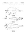
- FIG. 6 depicts approximate flame shapes for different operational settings of the co-annular burner configuration illustrated in FIG. 3.
- the burner configuration 10 illustrated in FIG. 1 includes a pair of generally tubular nozzles 20,30 arranged side-by-side with their longitudinal axes parallel.
- the nozzles 20,30 are supplied with fuel, typically natural gas, by respective feed pipes 22,32, from a common delivery pipe 15 via respective control valves 24,34.
- Nozzle 20 is a precessing jet nozzle and nozzle 30 a simple turbulent jet nozzle.
- FIG. 2 An example of a suitable precessing jet nozzle 20' is depicted in FIG. 2, and includes an axisymetric chamber 40 with a simple 42 or profiled 42' inlet aperture defining a large sudden expansion at the chamber's inlet end, and a small peripheral lip 44 defining an exit port 46.
- the fuel jet 48 enters chamber 40 at aperture 42 or 42' and is there separated from the chamber wall. The jet then reattaches asymmetrically at 50 to the inside of the wall and at the nozzle exit is deflected (52) at a large angle (eg 45°) from the nozzle axis by strong local pressure gradients.
- precessing jet nozzles are disclosed in international patent application PCT/AU88/00114 (publication no. WO88/08104) and in the associated national and regional patent publications including U.S. Pat. No. 5,060,867.
- the turbulent jet nozzle 20 may be, eg, a straight tube burner pipe, a single channel for gas without the use of primary air.
- This nozzle type operates as a turbulent jet and the kinetic energy of the fuel jet is progressively dissipated by mixing and entrainment with the surrounding air.
- its mixing characteristics are quite different from those of the nozzle 20' as depicted in FIG. 2.
- Other kinds of burner nozzle may be used for the nozzle 30, for example a burner using some cold primary air, eg 15% of the total air entrained, to increase the momentum of the gas jet and hence the entrainment capacity of the stream.
- the precessing jet nozzle 20 produces a shorter more radiant flame, while the simple turbulent jet nozzle 30 itself produces a long convective flame.
- the proportions of fuel flow to the respective nozzles can be varied so that the combined flame and the resultant heat release profile of the combined flame can be tailored to the requirements of the kiln.
- a cement clinker kiln it has been found that, not only does the burner configuration of FIG. 1 enable the combined flame to be controlled to suit the given type of cement clinker, it also enables greater control of the kiln to be achieved and facilitates the relatively easy removal of rings of coating which occasionally form.
- the clinker in the burning zone within the kiln ie where the clinker undergoes the exothermic clinkering reaction and reaches its maximum temperature, is sticky and forms a coating on the refractory brick lining within the kiln.
- This is an advantage to the operation since the coating acts as an insulating layer which protects the bricks.
- an annular ring of coating can develop which causes the clinker to build up behind it. If the ring breaks, a rush of clinker through the kiln can cause serious problems and may result in damage to the plant.
- the development of a ring is related to the heat release profile, so that the ability to vary that profile with a burner configuration according to the invention facilitates the early removal of a ring before it becomes a problem.
- FIGS. 3 to 5 illustrate alternative embodiments of burner configuration according to the invention, in which like components are indicated by like two-digit reference numerals preceded by different integers.
- the arrangement shown in FIG. 3 comprises a concentric pipe burner configuration 210, consisting of a precessing jet nozzle 220 mounted substantially concentrically within an outer pipe 230 defining a co-annular burner pipe.
- the co-annular pipe 230 may or may not have a flow-directing nozzle in the end and may or may not be used to cool the inner nozzle/burner 220.
- a flow-directing nozzle 332 is used to swirl the co-annular flow
- a co-annular swirl burner 310 is produced: this is depicted in FIG.
- FIG. 5 is an end view of a multi-pipe burner configuration 410, consisting of a ring of four equiangularly spaced precessing jet nozzles/burners 420 arranged around one or more turbulent jet nozzles/burners 430. Jet nozzles/burners 420 are supported by radial spacer elements 421.
- the converse--a ring of turbulent jet nozzles/burners around one or more precessing jet nozzles/burners-- is of course also an option within the broad scope of the invention.
- valves 24,34;224,234 etc is only one of a variety of possible arrangements for varying the ratio of flow to any of the two or more nozzles.
- a single valve may be used to control the ratio of flows through the respective nozzles.
- FIG. 6 depicts approximate flame shapes for different operational settings of the co-annular burner configuration illustrated in FIG. 3.
- the flame 101 is highly luminous and relatively bulbous.
- Flame 101 is a highly radiant but relatively low temperature flame close to the nozzle exit.
- the flame 102 FIG. 6(b)! is relatively long and thin, projecting further from the nozzle.
- Flame 102 is moreover an initially and mainly higher temperature blue flame with an orange tail.
- the combined flame 103 depicted in FIG. 6(c) is for a proportional delivery of fuel of 60% to precessing jet nozzle 220 and 40% to co-annular nozzle 230.
- Flame 103 is highly luminous throughout and a mix of the features of flames 101,102.
Landscapes
- Engineering & Computer Science (AREA)
- Mechanical Engineering (AREA)
- General Engineering & Computer Science (AREA)
- Chemical & Material Sciences (AREA)
- Combustion & Propulsion (AREA)
- Gas Burners (AREA)
- Combustion Of Fluid Fuel (AREA)
Abstract
A burner configuration includes at least one processing jet nozzle and at least one further burner nozzle having mixing characteristics different from the processing jet nozzle. A means is preferably provided to control the proportions of fuel flow to the nozzles. The nozzles of the set are in sufficient proximity that a combined flame of the burner configuration can be determined or controlled by setting or varying the relative flows of fuel to the nozzle of the set.
Description
This invention relates to a burner configuration and in preferred embodiments to a variable flame burner configuration. The invention has particular though certainly not exclusive application to a variable flame burner fuelled by natural gas and is applicable to kilns such as rotary cement kilns, furnaces and other process heating arrangements. The invention also relates to a method of generating a burner flame.
The present applicant's international patent publication WO88/08104 (PCT/AU88/00114) and the associated U.S. Pat. No. 5,060,867 disclose a fluid mixing nozzle in which a primary flow of a first fluid separates from the internal wall structure and reattaches itself asymmetrically to the wall upstream of the nozzle outlet. A flow of a second fluid induced through the outlet swirls in the chamber between the flow separation and reattachment and induces precession of the separated reattached flow, which exits the nozzle asymmetrically. This nozzle has come to be termed a precessing jet nozzle and such terminology is adopted herein. By the optional addition of a centre-body within the chamber, part of the primary flow can be caused to recirculate within the chamber and induce the precession.
When the precessing jet nozzle is operated as a burner, using eg natural gas as the fuel and primary flow, it has been observed that, in comparison with a simple turbulent jet burner, the precessing jet nozzle generates a more bulbous flame whose stand-off distance is reduced by an order of magnitude and whose blow-off velocity is increased by a factor of four. These features have been found to enhance the stability and radiation characteristics of the flame in furnaces and boilers and to enhance the performance of kilns such as rotary cement kilns employed to produce cement clinker. Both the quality of the clinker produced in such kilns and the energy required to produce it, are significantly influenced by the "heat release profile" of the flame generated by the burner and by the proportion of the energy which is radiated, as opposed to being convected, to the product. The heat release profile of the flame is the proportion of the total energy which is released in each part of the kiln, and it will thus be appreciated that the precessing jet burner, with its closer bulbous flame and higher blow-off velocity, is well suited in principle to kiln application.
Preliminary trials of the precessing jet nozzle burner in a cement kiln have demonstrated a reduction in NOX emissions by up to 75% relative to a more conventional turbulent jet burner and have shown potential to benefit the clinkering process. However, the flame has been found to release too much heat at the front of the kiln during some phases of the kiln operation, which adversely affects the life of the refractory bricks. Similar constraints may be anticipated in some applications of the precessing jet nozzle burner to other direct process heating in, for example, the metals, glass and chemical industries.
In accordance with the invention, it has been realised that the aforementioned problem can be overcome, and perhaps other advantages obtained, by providing a burner configuration including at least one precessing jet nozzle and at least one further burner nozzle having mixing characteristics different from the precessing jet nozzle.
Most generally, the invention provides a burner configuration comprising a set of fuel nozzles including at least one precessing jet nozzle and at least one further nozzle having mixing characteristics which are different from the precessing jet nozzle.
Preferably, the burner configuration further includes means to set or control the proportions of fuel flow to the nozzles, wherein the nozzles of the set are in sufficient proximity that the combined flame of the burner configuration can be determined or controlled by setting or varying the relative flows of fuel to the nozzles of the set.
The further nozzle(s) may be a simple turbulent jet nozzle, eg a straight pipe nozzle, whereby the precessing jet nozzle produces a flame which is relatively shorter and more radiant and the flame of the further nozzle(s) is relatively longer and more convective.
The precession of the jet emerging from the precessing jet nozzle causes mainly large scale mixing of the jet with the surrounding fluid. The jet from a conventional nozzle produces mainly fine scale mixing with the surrounding fluid. By combining the two types of nozzle and adjusting the proportions of the fuel flows through each, the mixing characteristics and hence the resulting flame shape can be modified. Further, the large scale mixing associated with the precessing jet nozzle causes a region of fuel-rich combustion which, for a gaseous fuel, generates a highly radiant but relatively low temperature flame close to the nozzle exit. By contrast, the fine scale mixing associated with a conventional jet nozzle generates an almost transparent high temperature blue flame with a gaseous fuel. The generation of NOX increases with flame temperature.
It will be appreciated that, by adjustment of the control means, the ratio of the total gas flow which is introduced through each nozzle can be varied so that the heat release profile of the combined flame can be tailored to the current requirements of the kiln or other process.
By "different mixing characteristics" herein, in relation to the burner nozzles, is meant that the mixing of fuel and air generated at the respective nozzles is sufficiently different in character for the resultant flames to have different characteristics, e.g. with respect to one or more of shape, width, length, luminosity, temperature and colour.
The invention also provides a method of generating a burner flame.
In the attached drawings:
FIG. 1 schematically depicts a simple burner configuration according to a first embodiment of the invention;
FIG. 2 is a diagrammatic cross-section of a precessing jet nozzle suitable for the burner configuration of FIG. 1, including a simple flow representation of the instantaneous pattern of the three-dimensional dynamically precessing and swirling flow thought to exist in and around the precessing jet nozzle once mixing has become established;
FIGS. 3 to 5 schematically illustrate respective alternative burner configurations according to further embodiments of the invention; and
FIG. 6 depicts approximate flame shapes for different operational settings of the co-annular burner configuration illustrated in FIG. 3.
The burner configuration 10 illustrated in FIG. 1 includes a pair of generally tubular nozzles 20,30 arranged side-by-side with their longitudinal axes parallel. The nozzles 20,30 are supplied with fuel, typically natural gas, by respective feed pipes 22,32, from a common delivery pipe 15 via respective control valves 24,34.
Nozzle 20 is a precessing jet nozzle and nozzle 30 a simple turbulent jet nozzle.
An example of a suitable precessing jet nozzle 20' is depicted in FIG. 2, and includes an axisymetric chamber 40 with a simple 42 or profiled 42' inlet aperture defining a large sudden expansion at the chamber's inlet end, and a small peripheral lip 44 defining an exit port 46. The fuel jet 48 enters chamber 40 at aperture 42 or 42' and is there separated from the chamber wall. The jet then reattaches asymmetrically at 50 to the inside of the wall and at the nozzle exit is deflected (52) at a large angle (eg 45°) from the nozzle axis by strong local pressure gradients. There are also strong azimuthal pressure gradients which cause the jet, and the entire flow field within the chamber, to precess about the nozzle axis. These pressure gradients and fields induce air 54 through the outlet 46 and this air swirls in the chamber at 55 between the flow separation and the reattachment and in part induces the precession of the separated/reattached flow. This precession enhances mixing of the fuel flow with the air from the exterior of the chamber.
Further particulars and embodiments of precessing jet nozzles are disclosed in international patent application PCT/AU88/00114 (publication no. WO88/08104) and in the associated national and regional patent publications including U.S. Pat. No. 5,060,867.
The turbulent jet nozzle 20 may be, eg, a straight tube burner pipe, a single channel for gas without the use of primary air. This nozzle type operates as a turbulent jet and the kinetic energy of the fuel jet is progressively dissipated by mixing and entrainment with the surrounding air. Thus, its mixing characteristics are quite different from those of the nozzle 20' as depicted in FIG. 2. Other kinds of burner nozzle may be used for the nozzle 30, for example a burner using some cold primary air, eg 15% of the total air entrained, to increase the momentum of the gas jet and hence the entrainment capacity of the stream.
With the burner configuration illustrated in FIG. 1, the precessing jet nozzle 20 produces a shorter more radiant flame, while the simple turbulent jet nozzle 30 itself produces a long convective flame. By relative adjustment of valves 24,34 using any suitable control means 25, which may be manual, the proportions of fuel flow to the respective nozzles can be varied so that the combined flame and the resultant heat release profile of the combined flame can be tailored to the requirements of the kiln. In the case of a cement clinker kiln, it has been found that, not only does the burner configuration of FIG. 1 enable the combined flame to be controlled to suit the given type of cement clinker, it also enables greater control of the kiln to be achieved and facilitates the relatively easy removal of rings of coating which occasionally form. To explain this latter point further, the clinker in the burning zone within the kiln, ie where the clinker undergoes the exothermic clinkering reaction and reaches its maximum temperature, is sticky and forms a coating on the refractory brick lining within the kiln. This is an advantage to the operation since the coating acts as an insulating layer which protects the bricks. However, under some conditions an annular ring of coating can develop which causes the clinker to build up behind it. If the ring breaks, a rush of clinker through the kiln can cause serious problems and may result in damage to the plant. The development of a ring is related to the heat release profile, so that the ability to vary that profile with a burner configuration according to the invention facilitates the early removal of a ring before it becomes a problem.
It has been established that the burner configuration depicted in FIG. 1 still achieves a 50% reduction in NOX, and yet results in a significant improvement in the quality of the cement clinker produced.
FIGS. 3 to 5 illustrate alternative embodiments of burner configuration according to the invention, in which like components are indicated by like two-digit reference numerals preceded by different integers. The arrangement shown in FIG. 3 comprises a concentric pipe burner configuration 210, consisting of a precessing jet nozzle 220 mounted substantially concentrically within an outer pipe 230 defining a co-annular burner pipe. The co-annular pipe 230 may or may not have a flow-directing nozzle in the end and may or may not be used to cool the inner nozzle/burner 220. In the case where a flow-directing nozzle 332 is used to swirl the co-annular flow, a co-annular swirl burner 310 is produced: this is depicted in FIG. 4, in which the swirl flow is indicated by arrow lines 329. FIG. 5 is an end view of a multi-pipe burner configuration 410, consisting of a ring of four equiangularly spaced precessing jet nozzles/burners 420 arranged around one or more turbulent jet nozzles/burners 430. Jet nozzles/burners 420 are supported by radial spacer elements 421. The converse--a ring of turbulent jet nozzles/burners around one or more precessing jet nozzles/burners--is of course also an option within the broad scope of the invention.
It is emphasised that the illustrated flow control means comprising valves 24,34;224,234 etc is only one of a variety of possible arrangements for varying the ratio of flow to any of the two or more nozzles. For example, when the pressure drops through each of the two nozzles or sets of nozzles are approximately the same, a single valve may be used to control the ratio of flows through the respective nozzles.
FIG. 6 depicts approximate flame shapes for different operational settings of the co-annular burner configuration illustrated in FIG. 3. With fuel delivered only to the inner precessing jet nozzle 220 FIG. 6(a)!, the flame 101 is highly luminous and relatively bulbous. Flame 101 is a highly radiant but relatively low temperature flame close to the nozzle exit. By contrast, with fuel delivered only to the co-annular jet nozzle 230, the flame 102 FIG. 6(b)! is relatively long and thin, projecting further from the nozzle. Flame 102 is moreover an initially and mainly higher temperature blue flame with an orange tail. The combined flame 103 depicted in FIG. 6(c) is for a proportional delivery of fuel of 60% to precessing jet nozzle 220 and 40% to co-annular nozzle 230. Flame 103 is highly luminous throughout and a mix of the features of flames 101,102.
A comparison was made between clinker produced in a cement clinker kiln with a traditional turbulent straight tube burner nozzle, and clinker produced with a burner configuration as illustrated in FIGS. 1 and 2, in which 63% of gas fuel was directed to the precessing jet nozzle. The smaller well-defined and colourful (aqua blue) alite crystals and smaller well-shaped belite crystals evident in the latter case were evident of a more reactive clinker, believed to be brought about by the improved heat profile in the kiln.
Claims (7)
1. A burner comprising a plurality of nozzles, at least one of said nozzles being a processing jet nozzle having a first fuel/air mixing characteristic to provide a first flame and at least one additional nozzle having a second fuel/air mixing characteristic different from said first mixing characteristic for providing a second flame different from said first flame, said nozzles being disposed adjacent each other to provide a combined flame different from said first and second flames,
wherein said at least one processing jet nozzle is comprised of a fluid mixing nozzle in which operation of a primary flow of a first fluid separates from an internal wall structure and reattaches itself asymmetrically to the wall structure upstream of a nozzle outlet whereby a flow of a second fluid is induced through the outlet swirling in a chamber between a point where said first fluid separates from said wall structure and a second point where said fluid reattaches itself to said wall structure for inducing precession of the separated and reattached flow which exits said nozzle asymmetrically.
2. A burner as set forth in claim 1, further comprising fuel supply means for supplying fuel to each of said nozzles and control means for controlling the proportions of fuel flow to said nozzles.
3. A burner as set forth in claim 1, wherein said at least one additional nozzle is a turbulent jet nozzle for producing a flame relatively longer and thinner than a relatively short bulbous flame produced by said precessing jet nozzle.
4. A burner as set forth in claim 1, wherein said nozzles extend in generally parallel adjacent spaced apart relation with respect to each other.
5. A burner as set forth in claim 1, wherein a plurality of additional nozzles are provided with said additional nozzles disposed in concentric relation about said precessing jet nozzle.
6. A burner as set forth in claim 1 wherein said nozzles are arranged generally concentrically with said precessing jet nozzle being substantially concentrically disposed within said at least one additional nozzle.
7. A burner as set forth in claim 6, further comprising fluid directing means for swirling fuel in said at least one additional nozzle about said precessing jet nozzle.
Applications Claiming Priority (3)
| Application Number | Priority Date | Filing Date | Title |
|---|---|---|---|
| AUPL482792 | 1992-09-18 | ||
| AUPL4827 | 1992-09-18 | ||
| PCT/AU1993/000476 WO1994007086A1 (en) | 1992-09-18 | 1993-09-17 | Variable flame burner configuration |
Publications (1)
| Publication Number | Publication Date |
|---|---|
| US5769624A true US5769624A (en) | 1998-06-23 |
Family
ID=3776429
Family Applications (1)
| Application Number | Title | Priority Date | Filing Date |
|---|---|---|---|
| US08/403,706 Expired - Lifetime US5769624A (en) | 1992-09-18 | 1993-09-17 | Variable flame burner configuration |
Country Status (5)
| Country | Link |
|---|---|
| US (1) | US5769624A (en) |
| EP (1) | EP0662208A4 (en) |
| MX (1) | MX9305747A (en) |
| NZ (1) | NZ255966A (en) |
| WO (1) | WO1994007086A1 (en) |
Cited By (12)
| Publication number | Priority date | Publication date | Assignee | Title |
|---|---|---|---|---|
| WO2003050449A1 (en) | 2001-12-13 | 2003-06-19 | Cemex, Inc. | LOW NOx PARTICULATE FUEL BURNER |
| US6685102B1 (en) * | 1997-11-18 | 2004-02-03 | Luminis Pty., Ltd. | Oscillating jets |
| US6938835B1 (en) * | 2000-12-20 | 2005-09-06 | Bowles Fluidics Corporation | Liquid scanner nozzle and method |
| US20060029896A1 (en) * | 2000-07-27 | 2006-02-09 | John Zink Company, Llc | Venturi cluster, and burners and methods employing such cluster |
| US20060068346A1 (en) * | 2004-09-30 | 2006-03-30 | Nowakowski John J | Heating method and apparatus |
| US20070037106A1 (en) * | 2005-08-12 | 2007-02-15 | Kobayashi William T | Method and apparatus to promote non-stationary flame |
| US20070287108A1 (en) * | 2004-01-22 | 2007-12-13 | Linde Aktiengesellschaft | Apparatus and Method for a Burner |
| US20080090194A1 (en) * | 2006-10-16 | 2008-04-17 | Stefan Laux | Stratified staging in kilns |
| US7410288B1 (en) | 1998-12-24 | 2008-08-12 | Luminis Pty. Ltd. | Fluid mixing device |
| US20150034164A1 (en) * | 2012-04-04 | 2015-02-05 | General Fusion, Inc. | Jet control devices and methods |
| US9909755B2 (en) | 2013-03-15 | 2018-03-06 | Fives North American Combustion, Inc. | Low NOx combustion method and apparatus |
| US9943863B2 (en) | 2015-04-29 | 2018-04-17 | Delta Faucet Company | Showerhead with scanner nozzles |
Families Citing this family (4)
| Publication number | Priority date | Publication date | Assignee | Title |
|---|---|---|---|---|
| AUPN156295A0 (en) * | 1995-03-07 | 1995-03-30 | Luminis Pty Limited | Variable flame precessing jet nozzle |
| DE19704802A1 (en) * | 1997-02-08 | 1998-08-13 | Ruhrgas Ag | Device and method for burning fuel |
| FR2795808B1 (en) * | 1999-07-02 | 2001-09-14 | Air Liquide | COMBUSTION PROCESS APPLICABLE TO THE MANUFACTURE OF CEMENT |
| FR2889579B1 (en) * | 2005-08-03 | 2007-09-14 | Air Liquide | METHOD FOR CALCINING A MATERIAL WITH LOW NOX EMISSION |
Citations (15)
| Publication number | Priority date | Publication date | Assignee | Title |
|---|---|---|---|---|
| DE501821C (en) * | 1930-07-05 | Hanseatische Appbau Ges Vorm L | Jet pipe for flame thrower with gas ignition | |
| US2138998A (en) * | 1936-06-24 | 1938-12-06 | John P Brosius | Burner unit |
| US2308902A (en) * | 1941-07-25 | 1943-01-19 | Gen Properties Company Inc | Method of producing heat radiating flames |
| US2531316A (en) * | 1946-08-09 | 1950-11-21 | John S Zink | Multiple fuel burner |
| US3671172A (en) * | 1969-03-28 | 1972-06-20 | Midland Ross Corp | Multifuel burner |
| US3954382A (en) * | 1974-04-08 | 1976-05-04 | Yasuo Hirose | Combustion apparatus and method |
| US4095929A (en) * | 1977-03-14 | 1978-06-20 | Combustion Engineering, Inc. | Low BTU gas horizontal burner |
| US4285663A (en) * | 1978-05-16 | 1981-08-25 | Boeder Wilfried | Process and apparatus for the continuous burning of a fuel |
| AU8899982A (en) * | 1981-10-02 | 1983-04-14 | Christopher John Abell | Mixing nozzles for fluid flow |
| US4505666A (en) * | 1981-09-28 | 1985-03-19 | John Zink Company | Staged fuel and air for low NOx burner |
| JPS6335814A (en) * | 1986-07-30 | 1988-02-16 | Kobayashi Textile Eng Kk | Apparatus for preventing generation of uneven fineness in automatic reeling machine |
| US4744748A (en) * | 1986-10-02 | 1988-05-17 | Wingaersheek Division Of Victor Equipment Company | Multiple burner torch tip |
| US4957050A (en) * | 1989-09-05 | 1990-09-18 | Union Carbide Corporation | Combustion process having improved temperature distribution |
| US5060867A (en) * | 1987-04-16 | 1991-10-29 | Luminis Pty. Ltd. | Controlling the motion of a fluid jet |
| US5163830A (en) * | 1991-08-29 | 1992-11-17 | Greene Manufacturing Company | Fuel-air mixer tube |
Family Cites Families (2)
| Publication number | Priority date | Publication date | Assignee | Title |
|---|---|---|---|---|
| DE1501982A1 (en) * | 1966-04-13 | 1970-01-15 | Dano Ingenioforretning & Maski | Burner unit for rotary furnaces |
| AU614518B2 (en) * | 1987-04-16 | 1991-09-05 | Luminis Pty Limited | Controlling the motion of a fluid jet |
-
1993
- 1993-09-17 US US08/403,706 patent/US5769624A/en not_active Expired - Lifetime
- 1993-09-17 WO PCT/AU1993/000476 patent/WO1994007086A1/en not_active Ceased
- 1993-09-17 NZ NZ255966A patent/NZ255966A/en not_active IP Right Cessation
- 1993-09-17 EP EP93920602A patent/EP0662208A4/en not_active Withdrawn
- 1993-09-20 MX MX9305747A patent/MX9305747A/en not_active IP Right Cessation
Patent Citations (15)
| Publication number | Priority date | Publication date | Assignee | Title |
|---|---|---|---|---|
| DE501821C (en) * | 1930-07-05 | Hanseatische Appbau Ges Vorm L | Jet pipe for flame thrower with gas ignition | |
| US2138998A (en) * | 1936-06-24 | 1938-12-06 | John P Brosius | Burner unit |
| US2308902A (en) * | 1941-07-25 | 1943-01-19 | Gen Properties Company Inc | Method of producing heat radiating flames |
| US2531316A (en) * | 1946-08-09 | 1950-11-21 | John S Zink | Multiple fuel burner |
| US3671172A (en) * | 1969-03-28 | 1972-06-20 | Midland Ross Corp | Multifuel burner |
| US3954382A (en) * | 1974-04-08 | 1976-05-04 | Yasuo Hirose | Combustion apparatus and method |
| US4095929A (en) * | 1977-03-14 | 1978-06-20 | Combustion Engineering, Inc. | Low BTU gas horizontal burner |
| US4285663A (en) * | 1978-05-16 | 1981-08-25 | Boeder Wilfried | Process and apparatus for the continuous burning of a fuel |
| US4505666A (en) * | 1981-09-28 | 1985-03-19 | John Zink Company | Staged fuel and air for low NOx burner |
| AU8899982A (en) * | 1981-10-02 | 1983-04-14 | Christopher John Abell | Mixing nozzles for fluid flow |
| JPS6335814A (en) * | 1986-07-30 | 1988-02-16 | Kobayashi Textile Eng Kk | Apparatus for preventing generation of uneven fineness in automatic reeling machine |
| US4744748A (en) * | 1986-10-02 | 1988-05-17 | Wingaersheek Division Of Victor Equipment Company | Multiple burner torch tip |
| US5060867A (en) * | 1987-04-16 | 1991-10-29 | Luminis Pty. Ltd. | Controlling the motion of a fluid jet |
| US4957050A (en) * | 1989-09-05 | 1990-09-18 | Union Carbide Corporation | Combustion process having improved temperature distribution |
| US5163830A (en) * | 1991-08-29 | 1992-11-17 | Greene Manufacturing Company | Fuel-air mixer tube |
Cited By (21)
| Publication number | Priority date | Publication date | Assignee | Title |
|---|---|---|---|---|
| US6685102B1 (en) * | 1997-11-18 | 2004-02-03 | Luminis Pty., Ltd. | Oscillating jets |
| US7410288B1 (en) | 1998-12-24 | 2008-08-12 | Luminis Pty. Ltd. | Fluid mixing device |
| US20060029896A1 (en) * | 2000-07-27 | 2006-02-09 | John Zink Company, Llc | Venturi cluster, and burners and methods employing such cluster |
| US6938835B1 (en) * | 2000-12-20 | 2005-09-06 | Bowles Fluidics Corporation | Liquid scanner nozzle and method |
| US20030157451A1 (en) * | 2001-12-13 | 2003-08-21 | Mccabe Michael I. | Low NOx particulate fuel burner |
| WO2003050449A1 (en) | 2001-12-13 | 2003-06-19 | Cemex, Inc. | LOW NOx PARTICULATE FUEL BURNER |
| US20070287108A1 (en) * | 2004-01-22 | 2007-12-13 | Linde Aktiengesellschaft | Apparatus and Method for a Burner |
| US20060068346A1 (en) * | 2004-09-30 | 2006-03-30 | Nowakowski John J | Heating method and apparatus |
| US7637739B2 (en) * | 2004-09-30 | 2009-12-29 | Fives North American Combustion, Inc. | Heating method and apparatus |
| US20070037106A1 (en) * | 2005-08-12 | 2007-02-15 | Kobayashi William T | Method and apparatus to promote non-stationary flame |
| US20080090194A1 (en) * | 2006-10-16 | 2008-04-17 | Stefan Laux | Stratified staging in kilns |
| WO2008048936A3 (en) * | 2006-10-16 | 2008-06-05 | Praxair Technology Inc | Stratified staging in kilns |
| US7452203B2 (en) | 2006-10-16 | 2008-11-18 | Praxair Technology, Inc. | Stratified staging in kilns |
| US9267515B2 (en) * | 2012-04-04 | 2016-02-23 | General Fusion Inc. | Jet control devices and methods |
| US20150034164A1 (en) * | 2012-04-04 | 2015-02-05 | General Fusion, Inc. | Jet control devices and methods |
| US9463478B2 (en) | 2012-04-04 | 2016-10-11 | General Fusion Inc. | Jet control devices and methods |
| US10092914B2 (en) | 2012-04-04 | 2018-10-09 | General Fusion Inc. | Jet control devices and methods |
| US9909755B2 (en) | 2013-03-15 | 2018-03-06 | Fives North American Combustion, Inc. | Low NOx combustion method and apparatus |
| US9943863B2 (en) | 2015-04-29 | 2018-04-17 | Delta Faucet Company | Showerhead with scanner nozzles |
| US10399094B2 (en) | 2015-04-29 | 2019-09-03 | Delta Faucet Company | Showerhead with scanner nozzles |
| US11241702B2 (en) | 2015-04-29 | 2022-02-08 | Delta Faucet Company | Showerhead with scanner nozzles |
Also Published As
| Publication number | Publication date |
|---|---|
| NZ255966A (en) | 1995-10-26 |
| EP0662208A4 (en) | 1997-10-22 |
| MX9305747A (en) | 1994-05-31 |
| WO1994007086A1 (en) | 1994-03-31 |
| EP0662208A1 (en) | 1995-07-12 |
Similar Documents
| Publication | Publication Date | Title |
|---|---|---|
| US5769624A (en) | Variable flame burner configuration | |
| US5454712A (en) | Air-oxy-fuel burner method and apparatus | |
| EP0877202B1 (en) | Oxy/Oil swirl burner | |
| EP0194079B1 (en) | Fluid fuel fired burner | |
| EP0343767B1 (en) | Burner for the combustion of pulverised fuel | |
| US5743723A (en) | Oxy-fuel burner having coaxial fuel and oxidant outlets | |
| AU709979B2 (en) | Combustion burner and combustion device provided with same | |
| KR100643630B1 (en) | Burner and method for combusting fuels | |
| US4556384A (en) | Burner for pulverized coal | |
| CZ49293A3 (en) | Combustion system employing oxygen and fuel | |
| US20140008454A1 (en) | HVOF Torch with Fuel Surrounding Oxidizer | |
| KR20010024477A (en) | Combustor with independently controllable fuel flow to different stages | |
| US3195609A (en) | Self stabilizing radiant tube burner | |
| EP1203188B1 (en) | Improved industrial burner for fuel | |
| US4732093A (en) | Annular nozzle burner and method of operation | |
| US3187799A (en) | Self-stabilizing combustion apparatus and method | |
| US4214866A (en) | Burner for high temperature combustion air | |
| CN103759263B (en) | A kind of pure oxygen process gas burner | |
| US1805066A (en) | Gas burner or nozzle | |
| US3208502A (en) | Fuel burners having air control means | |
| US4768948A (en) | Annular nozzle burner and method of operation | |
| US2857148A (en) | Method of firing rotary kilns and gas burner therefor | |
| AU673686B2 (en) | Variable flame burner configuration | |
| WO1996027761A1 (en) | Variable flame precessing jet nozzle | |
| GB1370135A (en) | Combustion apparatus |
Legal Events
| Date | Code | Title | Description |
|---|---|---|---|
| AS | Assignment |
Owner name: LUMINIS PTY. LTD., AUSTRALIA Free format text: ASSIGNMENT OF ASSIGNORS INTEREST;ASSIGNORS:LUXTON, RUSSELL ESTCOURT;NATHAN, GRAHAM JERROLD;REEL/FRAME:007695/0418 Effective date: 19950418 |
|
| STCF | Information on status: patent grant |
Free format text: PATENTED CASE |
|
| FPAY | Fee payment |
Year of fee payment: 4 |
|
| FPAY | Fee payment |
Year of fee payment: 8 |
|
| FPAY | Fee payment |
Year of fee payment: 12 |