US5768953A - Methods and systems for improving the operation of transmissions for motor vehicles - Google Patents
Methods and systems for improving the operation of transmissions for motor vehicles Download PDFInfo
- Publication number
- US5768953A US5768953A US08/697,625 US69762596A US5768953A US 5768953 A US5768953 A US 5768953A US 69762596 A US69762596 A US 69762596A US 5768953 A US5768953 A US 5768953A
- Authority
- US
- United States
- Prior art keywords
- shift valve
- valve
- fluid flow
- shift
- gear
- Prior art date
- Legal status (The legal status is an assumption and is not a legal conclusion. Google has not performed a legal analysis and makes no representation as to the accuracy of the status listed.)
- Expired - Lifetime
Links
Images


Classifications
-
- F—MECHANICAL ENGINEERING; LIGHTING; HEATING; WEAPONS; BLASTING
- F16—ENGINEERING ELEMENTS AND UNITS; GENERAL MEASURES FOR PRODUCING AND MAINTAINING EFFECTIVE FUNCTIONING OF MACHINES OR INSTALLATIONS; THERMAL INSULATION IN GENERAL
- F16H—GEARING
- F16H61/00—Control functions within control units of change-speed- or reversing-gearings for conveying rotary motion ; Control of exclusively fluid gearing, friction gearing, gearings with endless flexible members or other particular types of gearing
- F16H61/02—Control functions within control units of change-speed- or reversing-gearings for conveying rotary motion ; Control of exclusively fluid gearing, friction gearing, gearings with endless flexible members or other particular types of gearing characterised by the signals used
- F16H61/0202—Control functions within control units of change-speed- or reversing-gearings for conveying rotary motion ; Control of exclusively fluid gearing, friction gearing, gearings with endless flexible members or other particular types of gearing characterised by the signals used the signals being electric
- F16H61/0204—Control functions within control units of change-speed- or reversing-gearings for conveying rotary motion ; Control of exclusively fluid gearing, friction gearing, gearings with endless flexible members or other particular types of gearing characterised by the signals used the signals being electric for gearshift control, e.g. control functions for performing shifting or generation of shift signal
- F16H61/0206—Layout of electro-hydraulic control circuits, e.g. arrangement of valves
-
- F—MECHANICAL ENGINEERING; LIGHTING; HEATING; WEAPONS; BLASTING
- F16—ENGINEERING ELEMENTS AND UNITS; GENERAL MEASURES FOR PRODUCING AND MAINTAINING EFFECTIVE FUNCTIONING OF MACHINES OR INSTALLATIONS; THERMAL INSULATION IN GENERAL
- F16H—GEARING
- F16H61/00—Control functions within control units of change-speed- or reversing-gearings for conveying rotary motion ; Control of exclusively fluid gearing, friction gearing, gearings with endless flexible members or other particular types of gearing
- F16H2061/0065—Modifying or tuning an existing transmission control for racing, e.g. adaptation of valves for very fast shifting
-
- Y—GENERAL TAGGING OF NEW TECHNOLOGICAL DEVELOPMENTS; GENERAL TAGGING OF CROSS-SECTIONAL TECHNOLOGIES SPANNING OVER SEVERAL SECTIONS OF THE IPC; TECHNICAL SUBJECTS COVERED BY FORMER USPC CROSS-REFERENCE ART COLLECTIONS [XRACs] AND DIGESTS
- Y10—TECHNICAL SUBJECTS COVERED BY FORMER USPC
- Y10T—TECHNICAL SUBJECTS COVERED BY FORMER US CLASSIFICATION
- Y10T74/00—Machine element or mechanism
- Y10T74/21—Elements
- Y10T74/2186—Gear casings
Definitions
- the methods and systems of the present invention are directed to the modification and improvement of transmissions for automotive vehicles of the type installed by the original equipment manufacturers.
- the invention is particularly directed to the improvement and modification of the automotive transmissions commonly known as the "E40D” which is "factory installed” in automotive vehicles manufactured by Ford Motor Company.
- a publication entitled "TRANSGO E40D-HD2 REPROGRAMMING KIT” (including 2 pages designated as “E40D--STICK VALVE BODY"), is an instruction sheet describing the manner in which an automotive transmission mechanic implements the modifications to the E40D Ford factory installed transmission to achieve the goals of the present invention.
- the disclosure of the aforementioned instruction sheet (hereinafter referred to as the Transgo Publication) in its entirety is also expressly incorporated by reference into the present patent application.
- a primary object of the present invention is to enable the driver of a vehicle having an E40D Ford transmission to select first gear at any time, thereby enabling the driver to obtain a "first" gear ratio whenever the gear selector lever is placed in the "1" position without regard to the actual vehicle speed. This objective is accomplished by modification of the structure and operation of the existing hydraulic circuits of the original transmission and the addition of a new hydraulic circuits to the original transmission.
- a further object of the present invention is to modify a "factory installed" E40D transmission, when designed for stick shift manual operation, to enable section of any gear ratio at any time, both with and without electronic controls.
- Methods, apparatus and systems are provided for modifying the structure, operation, and functional relationship between structure in "factory installed” transmissions for automotive vehicles.
- the transmission identified as Model E40D installed in vehicles produced by The Ford Motor Company are modified to enable the driver to select any available ratio at any time, and in particular to enable the driver to obtain a first ratio whenever the gear selector is placed in the first position.
- the first ratio cannot be obtained for vehicle speeds exceeding approximately 34 miles per hour.
- the original transmission is modified to achieve this result by removing an existing 2-3 shift valve from the original hydraulic circuitry, and replacing it with a new 2-3 shift valve providing a fluid flow path through the valve itself to control fluid pressure applied to one side of the "1-2" shift valve to maintain or downshift the transmission to first gear ratio without regard to vehicle speed.
- the modification to the stick shift manual operation of the transmission enabling the selection of any gear ratio at any time without electronic controls includes the addition of a new 3-4 shift valve using the original spring, and the addition of a new 2-3 shift valve to adjust the pressure applied in the factory installed transmission to maintain maximum mainline pressure without electronic controls.
- the present invention also modifies the aforementioned "factory installed” automotive transmission by producing quick “applies” and “releases” with minimum ratio sharing (overlap), which is advantageous in improving performance when the vehicle is used for heavy duty applications.
- These further modifications to the operation of the original transmissions are achieved by enlarging or reducing (or plugging) orifices in the original hydraulic circuitry to modify fluid flow therethrough for controlling the apply and release fluid flow. Additionally, adjustments are made to spring and pressure values of the original transmission hydraulic circuitry for increasing minimum and maximum mainline pressure.
- the object of the present invention is to modify the operation of existing "factory installed" automotive transmissions, and in particular the Ford E40D transmission, to result in changes to the hydraulic circuitry and fluid flow therethrough to enable the driver of the vehicle to select any available ratio at any time in a stick shift manual operating mode without electronic controls, to select first gear ratio without regard to vehicle speed, and to produce quick "applies and releases" which are particularly advantageous for heavy duty applications.
- Other advantages and improvements of the methods, systems and apparatus of the present invention will become apparent to those skilled in the automotive transmission art from the following discussion in conjunction with the enclosed drawings.
- FIGS. 1A-1D illustrate the prior art hydraulic circuitry of the "factory installed” Ford E40D automotive transmission for First Gear position
- FIGS. 2A-2D illustrates the hydraulic circuitry of the Ford E40D automotive transmission in the "1 Position First Gear", as modified in accordance with the present invention.
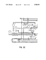
- FIGS. 3A-3D illustrates the hydraulic circuitry of the Ford E40D transmission in the "D Position Fourth Gear", as modified in accordance with the present invention.
- the present invention is directed to improvements and modifications to existing "factory installed" automotive transmissions, and in particular the E40D transmission of The Ford Motor Company, Dearborn, Mich.
- the objects of the present invention include modification of the structure, hydraulic circuitry, interrelationship of structure and fluid flow patterns through the hydraulic circuitry of the original factory installed transmission for the purpose of 1). enabling a driver to select first gear ratio without regard to vehicle speed, 2). enabling a driver to select any available ratio at any time with or without electronic controls in stick shift manual operation, and 3). controlling fluid flow through the hydraulic circuitry to produce quick apply forces during upshifts and quick releases during downshifts with minimum ratio sharing (overlap) during gear changes.
- the modifications to the original operation and hydraulic circuitry of the "factory installed" automotive transmission are accomplished by eliminating structure including original valves, adding structure including new valves, adding new hydraulic circuits to the overall circuitry, discontinuing use of existing circuits by plugging; and modifying flow of hydraulic fluid through existing hydraulic circuitry by enlarging or reducing the size of fluid flow orifices and adjusting existing spring and pressure values.
- FIG. 1 of the drawings illustrates the prior art operation of the "factory installed" E40D transmission in First Gear position.
- FIGS. 2-3 (shown as FIGS. 2A-2D, and 3A-3D, respectively illustrate the hydraulic circuitry of the E40D automotive transmission, as modified from the "factory installed" mode of operation in accordance with the present invention.
- FIG. 1 of the drawing illustrates operation of the "factory installed" E40D transmission in the First Gear postion. The mode of operation of this factory installed transmission, which is known to those skilled in the art, is described in detail in the aforementioned Ford publication to which further reference is made.
- FIGS. 2-3 of the drawing illustrate the hydraulic circuity of the "factory installed” E40D transmission, as modified in accordance with the preferred embodiments of the present invention.
- the "factory installed" 2-3 shift valve is replaced by a new 2-3 shift valve designated by reference numeral 2 in FIGS. 2-3 of the drawing.
- a fluid flow path designated by reference numeral 4 is defined through the center of the valve 2.
- Low oil flows through the passageway 4 to the left end of the valve 2, applying a pressure thereto.
- the applied pressure at the left end of the valve 2 actuates the valve causing it to move in a rightward direction when a gear selector is placed in a "1" or First Gear position.
- the valve 2 is thus held in a downshifted position to the right (as shown in FIG.
- the "1-2" shift valve In the factory installed transmission, to prevent the engine from attaining a rotational speed greater than that corresponding to a vehicle speed of approximately 34 m.p.h. when the gear selector is in the "1" or First Gear position, the "1-2" shift valve was allowed to upshift (move in a leftward direction as illustrated in FIG. 1 of the drawing) by electrically de-energizing a solenoid associated with the factory installed "1-2" shift valve. In this manner, solenoid oil is exhausted from the left end of the "1-2" shift valve reducing the fluid force applied to that end of the valve, thereby allowing a spring acting on the right end of the valve to exert a sufficient force to upshift the valve by moving it in a leftward direction.
- the hydraulic system of the "factory installed" E40D transmission is modified to prevent the "1-2" shift valve, designated by reference numeral 6 in FIG. 2 of the drawing, from upshifting (moving leftward as shown in the drawing) when the gear selector is in the "1" or First Gear position.
- This modification is accomplished by feeding low oil through the passageway 4 defined through the center of the "2-3" shift valve, designated by reference numeral 2 in FIG. 2 of the drawing, to the left end of the "1-2" shift valve, designated by reference numeral 6 in FIG. 2 of the drawing.
- appropriate fluid flow passageways are provided for coupling shift valve 2 (and the passageway 4 defined in the center thereof) in fluid flow relationship to the left end of the shift valve 6.
- the fluid pressure applied to the left end of the valve 6 prevents the valve from upshifting (moving leftward as shown in the drawing) even in the event that the solenoid associated with shift valve 2 is de-energized (as for example by computer controls) to exhaust solenoid oil from the left end of the "1-2" shift valve.
- a check ball designated by reference numeral 8 in FIG. 2 of the drawing, is provided at the left end of the "2-3" shift valve 2 to prevent solenoid oil pressure from exhausting to atmosphere when the gear selector is not in the "1" or First Gear position. (See FIG. 3 of the drawing).
- a spring 10 provided at the stem end of the shift valve 2 retains the check ball 8 at its operating position on the valve.
- the "1-2" valve is maintained in a downshifted (rightwardly oriented position as shown in FIGS. 2-3 of the drawing) until the gear selector lever is moved out of the "1" first gear position.
- the gear selector lever is moved out the "1" position, manual low/1st oil is exhausted at the manual valve, designated by reference numeral 12 in FIGS. 2-3 of the drawing.
- the solenoid associated with the "1-2" shift valve 6 See, for example, FIG. 2 of the drawing) is not energized, permitting solenoid oil to exhaust from the left end of the "1-2” shift valve. This results in movement of the "1-2" shift valve in a leftward direction (as shown in FIGS.
- the E40D "factory installed" transmission for stick shift manual operation is modified to enable the driver to manually select any gear ratio at any time during operation of the vehicle (i.e., without regard to actual vehicle speed or rotational engine speed) without employing computer controls.
- This modification requires the removal of the factory installed "2-3" shift valve, the installation of a new "2-3" shift valve including a 3/16 inch checkball and a spring on the stem end of the new valve (See FIGS. 2-3 of the drawing), removal of the "factory installed” "3-4" shift valve, and installation of a new "3-4" shift valve using the "factory installed” spring for the original "3-4" shift valve. (See FIG. 3). Attention is also directed to the portion of the aforementioned Trango publication, entitled “E40D-Stick Valve Body”.
- the "stick shift” or “manually operated” transmission design functions without electronic controls.
- the command wires to the appropriate shift solenoids and EPC solenoid must be disconnected.
- solenoid oil is absent from the left end of the shift valves associated with each solenoid (since all solenoids are open to exhaust), thereby causing mainline pressure to achieve its maximum value.
- First gear position is held as a result of the action of a new "2-3" shift valve, the operation thereof having been previously discussed herein, enabling the driver to achieve first gear at any rotational speed of the engine.
- solenoid pressure is absent from the new "2-3" shift valve, designated by reference numeral 2 in FIGS. 2-3 of the drawing.
- the valve 2 is prevented from upshifting, (i.e., moving in a leftward direction as indicated in the drawings) by 2nd oil acting on the second land from the left to hold the "2-3" shift valve in its rightward position.
- the solenoid is energized by applying 12 volts of electrical potential to the number 2 solenoid through a manual toggle switch. Accordingly, the E40D transmission, when operated in its stick shift manual mode, is run with no electronic controls from a computer so that 4th gear is attained as a result of the manual actuation of an electrical switch to energize a solenoid.
- the new "3-4" shift valve in accordance with the present invention has also been redesigned to move in a rightward direction (as seen on FIGS. 2-3 of the drawing) as compared to the "factory installed" 3-4 shift valve which moves in a leftward direction when upshifting into 4th gear. This revision is made so that it is possible to achieve 4th gear by energizing the number 2 solenoid which is associated with the "3-4" shift valve and causes the valve to move in a rightward direction as seen in the drawings.
- any fluid that might become trapped between the first and second lands (as viewed from the left in the drawings) on the new "3-4" shift valve in accordance with the present invention will be exhausted as a result of the undersize in the first land.
- This in turn, will prevent any fluid trapped between the first and second lands from holding the "3-4" shift valve in its rightward position as viewed in FIGS. 2-3 of the drawing.
- the entire circuit of the number 2 solenoid (the solenoid associated with the "3-4 shift valve") provides means for exhausting at the left end of the modified "3-4 shift valve" installed in accordance with the present invention.
- the new "3-4" shift valve which has been provided for manual operation as described above, is removed and replaced with original "factory installed” "3-4" shift valve and the original factory installed "3-4" shift valve spring.
- the new “2-3” shift valve also described above, which was installed for manual operation, is removed, and the new “2-3 shift valve” adapted for automatic operation in accordance with the present invention, is installed.
- the new "2-3 shift valve” for automatic operation is further modified for manual operation by redesigning the second and third lands from the left as seen in the drawing figures into a single longer land. It is necessary to replace the manual operation "2-3 shift valve” with the automatic "2-3 shift valve” when converting the hydraulic system back to automatic shifts as a result of the reverse nature of the operation of the "3-4 shift valve” for manual stick shift operation, as described herein. This allows conversion back to automatic by changing the "2-3" and the "3-4" shift valves, which were redesigned for manual operation, to the appropriate design of the valves for automatic operation, as previously discussed herein.
- the "factory installed" E40D transmission is modified to produce quick apply forces and release forces within minimum ratio sharing (overlap) to result in high performance operation of the modified transmission with correctly timed shifts. This objective is achieved by modification of the E40D "factory installed" transmission, discussed as follows.
- the minimum and maximum mainline pressure is increased.
- a spring is provided to increase maximum mainline pressure by approximately twenty pounds per square inch (psi), while a new boost assembly designated by reference numeral 16 in FIG. 2 provides higher line modulator pressure at mid to wide open throttle for providing firmer shifts.
- the spring acts on the boost valve of the factory installed transmission to enable the new boost valve assembly 16 to furnish line modulator pressure greater than in the factory installed transmission.
- the new boost assembly 16 in accordance with the present invention is larger in diameter than the "factory installed" boost assembly, and is calibrated with tapered springs.
- the boost assembly 16 is sensitive to EPC (electronic pressure control) from the EPC solenoid, and the EPC solenoid is sensitive to throttle opening which provides a signal (through change in oil pressure) to the boost assembly 16 to increase line modulator pressure applied to the accumulator valves of the factory installed transmission to result in firmer shifts than are otherwise provided by the unmodified factory installed transmission.
- the factory installed E40D transmission is modified to provide firmer and more correctly timed shift by enlarging three orifices, preferably to a diameter of 0.081 inches, as designated by reference numeral 18 in FIG. 3 of the drawing.
- the modified orifices are the third exhaust, the intermediate band apply, and the intermediate band (apply and exhaust) of the factory installed transmission. Attention is directed to page 2, step 5 of the Trango Publication, entitled “E40D-HD2 REPROGRAMMING KIT”.
- the tension springs for the second, third and fourth accumulators are modified to provide for shorter shifts. See page 1, step 3 of the Trango Publication entitled “E40D-HD2 REPROGRAMMING KIT”.
- reference numeral 20 designates a spring acting as a shim for preventing the "4-3-2" manual timing valve (designated as reference numeral 22) from moving in a stroking motion. In this manner, reverse delayed engagement is reduced by a reduction in the quantity of pump volume necessary to stroke the manual timing valve 22. Attention is also directed to page 1, step 2 of the Trango Publication entitled “E40D-HD2 REPROGRAMMING KIT”.
- a spring is provided for applying a resilient force to the converter valve of the factory installed E40D transmission to raise torque converter pressure (See, page 4, item A of the Trango Publication entitled “E40D-HD2 REPROGRAMMING KIT” ). Increased torque converter pressure increases lockup capacity which enhances the durability of the torque converter.
- an opening is drilled into the converter cover to provide an exhaust for cover pressure.
- cover pressure in the factory installed transmission detracts from (and opposes) the apply pressure during lockup, to provide a smooth lockup engagement.
- cover side pressure By drilling and exhausting the cover side pressure, less resistance is provided to the apply pressure during lockup, thereby resulting in firmer engagement and increased durability of the torque converter.
- a passage 24 (as shown in FIG. 3 of the drawing) is drilled to permit line pressure to bypass the pressure regulator valve (designated by reference numeral 26 in FIG. 3 of the drawing) of the factory installed hydraulic circuit in the event that the pressure regulator valve 26 fails to open during operation of the transmission.
- the hydraulic circuitry of a "factory installed" E40D transmission produced by the Ford Motor Company is modified to improve the overall performance thereof.
- the improvements include modifications to permit the operator of a vehicle to select and achieve first gear without regard to rotational speed of the engine or actual speed of the vehicle; to enable the operator of the vehicle to select any gear ratio at any time without computer controls when the transmission is in a stick shift--manual operation mode; and to modify fluid pressure and/or direction of fluid flow within the factory installed transmission to result in quick applies and releases with minimum ratio sharing (overlap) thereby providing firmer and more correctly timed shifts.
Landscapes
- Engineering & Computer Science (AREA)
- General Engineering & Computer Science (AREA)
- Mechanical Engineering (AREA)
- Control Of Transmission Device (AREA)
Abstract
Description
Claims (20)
Priority Applications (1)
| Application Number | Priority Date | Filing Date | Title |
|---|---|---|---|
| US08/697,625 US5768953A (en) | 1996-08-28 | 1996-08-28 | Methods and systems for improving the operation of transmissions for motor vehicles |
Applications Claiming Priority (1)
| Application Number | Priority Date | Filing Date | Title |
|---|---|---|---|
| US08/697,625 US5768953A (en) | 1996-08-28 | 1996-08-28 | Methods and systems for improving the operation of transmissions for motor vehicles |
Publications (1)
| Publication Number | Publication Date |
|---|---|
| US5768953A true US5768953A (en) | 1998-06-23 |
Family
ID=24801865
Family Applications (1)
| Application Number | Title | Priority Date | Filing Date |
|---|---|---|---|
| US08/697,625 Expired - Lifetime US5768953A (en) | 1996-08-28 | 1996-08-28 | Methods and systems for improving the operation of transmissions for motor vehicles |
Country Status (1)
| Country | Link |
|---|---|
| US (1) | US5768953A (en) |
Cited By (20)
| Publication number | Priority date | Publication date | Assignee | Title |
|---|---|---|---|---|
| US5967928A (en) * | 1997-06-09 | 1999-10-19 | Younger; Gilbert W. | Methods and systems for improving the operation of transmissions for motor vehicles |
| US6007445A (en) * | 1998-02-03 | 1999-12-28 | Ford Global Technologies, Inc. | Static forward and reverse engagement control system for a multiple ratio automatic transmission |
| US6117047A (en) * | 1999-01-08 | 2000-09-12 | Younger; Gilbert W. | Method and systems for improving the operation of transmissions for motor vehicles |
| US6213915B1 (en) * | 1999-01-29 | 2001-04-10 | Lentec Automatics Inc. | Apparatus and method of modifying an overdrive automatic transmission |
| US6565472B1 (en) | 2000-03-03 | 2003-05-20 | Younger Gilbert W | Method and systems for improving the operation of transmissions for motor vehicles |
| US20040214679A1 (en) * | 2002-02-21 | 2004-10-28 | Younger Gilbert W. | Methods and systems for improving the operation of transmissions for motor vehicles |
| US6814680B2 (en) | 2002-02-11 | 2004-11-09 | Gilbert W. Younger | Methods and systems for improving the operation of transmissions for motor vehicles |
| US20050090369A1 (en) * | 2003-10-24 | 2005-04-28 | Younger Gilbert W. | Methods and systems for improving the operation of transmissions for motor vehicles |
| US20050272549A1 (en) * | 2004-06-01 | 2005-12-08 | Carne Gary S | Transmission pressure modulation by orificed check valve |
| US9429228B2 (en) | 2012-06-25 | 2016-08-30 | Silent Partner Grants | Methods for improving the operation of transmissions for motor vehicles |
| US9970534B2 (en) | 2011-08-08 | 2018-05-15 | Transgo, Llc | Methods and systems for improving the operation of transmissions for motor vehicles |
| US20180172146A1 (en) * | 2015-06-23 | 2018-06-21 | Mazda Motor Corporation | Valve body for hydraulic control device, and production method therefor |
| US20180180070A1 (en) * | 2015-06-23 | 2018-06-28 | Mazda Motor Corporation | Valve body for hydraulic control device, and production method therefor |
| US10724628B2 (en) | 2017-06-29 | 2020-07-28 | Transgo, Llc | Methods and systems for improving the operation of transmissions for motor vehicles |
| US10948059B2 (en) | 2017-10-16 | 2021-03-16 | Transgo, Llc | Input drum for transmissions for motor vehicles |
| US11105415B2 (en) | 2018-07-03 | 2021-08-31 | Transgo, Llc | Methods and systems for improving the operation of transmissions for motor vehicles |
| US11408447B2 (en) | 2018-06-11 | 2022-08-09 | Transgo, Llc | Methods and systems for improving the operation of transmissions for motor vehicles |
| US12078243B2 (en) | 2022-07-20 | 2024-09-03 | Transgo, Llc | Methods and systems for improving the operation of transmissions for motor vehicles |
| US12345328B2 (en) | 2022-05-31 | 2025-07-01 | Transgo, Llc | Methods and systems for improving the operation of transmissions for motor vehicles |
| US12435786B2 (en) | 2022-01-18 | 2025-10-07 | Transgo, Llc | Methods and systems for improving the operation of transmissions for motor vehicles |
Citations (2)
| Publication number | Priority date | Publication date | Assignee | Title |
|---|---|---|---|---|
| US5540628A (en) * | 1994-11-02 | 1996-07-30 | Younger; Gilbert W. | Methods and systems for improving the operation of transmissions for motor vehicles |
| US5624342A (en) * | 1995-06-26 | 1997-04-29 | Younger; Gilbert W. | Method for modifying an original automatic transmission |
-
1996
- 1996-08-28 US US08/697,625 patent/US5768953A/en not_active Expired - Lifetime
Patent Citations (2)
| Publication number | Priority date | Publication date | Assignee | Title |
|---|---|---|---|---|
| US5540628A (en) * | 1994-11-02 | 1996-07-30 | Younger; Gilbert W. | Methods and systems for improving the operation of transmissions for motor vehicles |
| US5624342A (en) * | 1995-06-26 | 1997-04-29 | Younger; Gilbert W. | Method for modifying an original automatic transmission |
Non-Patent Citations (4)
| Title |
|---|
| Ford Motor Co., E40D Automatic Transmission Reference Manual, pp. 1 110, 1992. * |
| Ford Motor Co., E40D Automatic Transmission Reference Manual, pp. 1-110, 1992. |
| Transgo, E40D HD2 Reprogramming Kit (TM), pp. 1 6, 1995. * |
| Transgo, E40D-HD2 "Reprogramming Kit"(TM), pp. 1-6, 1995. |
Cited By (27)
| Publication number | Priority date | Publication date | Assignee | Title |
|---|---|---|---|---|
| US5967928A (en) * | 1997-06-09 | 1999-10-19 | Younger; Gilbert W. | Methods and systems for improving the operation of transmissions for motor vehicles |
| US6099429A (en) * | 1997-06-09 | 2000-08-08 | Younger; Gilbert W. | Method and systems for improving the operation of transmission for motor vehicles |
| US6287231B1 (en) | 1997-06-09 | 2001-09-11 | Gilbert W. Younger | Methods and systems for improving the operation of transmissions for motor vehicles |
| US6390944B1 (en) * | 1997-06-09 | 2002-05-21 | Gilbert W. Younger | Methods and systems for improving the operation of transmissions for motor vehicles |
| US6007445A (en) * | 1998-02-03 | 1999-12-28 | Ford Global Technologies, Inc. | Static forward and reverse engagement control system for a multiple ratio automatic transmission |
| US6117047A (en) * | 1999-01-08 | 2000-09-12 | Younger; Gilbert W. | Method and systems for improving the operation of transmissions for motor vehicles |
| US6213915B1 (en) * | 1999-01-29 | 2001-04-10 | Lentec Automatics Inc. | Apparatus and method of modifying an overdrive automatic transmission |
| US6565472B1 (en) | 2000-03-03 | 2003-05-20 | Younger Gilbert W | Method and systems for improving the operation of transmissions for motor vehicles |
| US6729989B2 (en) * | 2000-03-03 | 2004-05-04 | Younger Gilbert W | Method and systems for improving the operation of transmissions for motor vehicles |
| US6814680B2 (en) | 2002-02-11 | 2004-11-09 | Gilbert W. Younger | Methods and systems for improving the operation of transmissions for motor vehicles |
| US20040214679A1 (en) * | 2002-02-21 | 2004-10-28 | Younger Gilbert W. | Methods and systems for improving the operation of transmissions for motor vehicles |
| US6871397B2 (en) * | 2002-02-21 | 2005-03-29 | Gilbert W. Younger | Methods and systems for improving the operation of transmissions for motor vehicles |
| US20050090369A1 (en) * | 2003-10-24 | 2005-04-28 | Younger Gilbert W. | Methods and systems for improving the operation of transmissions for motor vehicles |
| US6964628B2 (en) * | 2003-10-24 | 2005-11-15 | Younger Gilbert W | Methods and systems for improving the operation of transmissions for motor vehicles |
| US20050272549A1 (en) * | 2004-06-01 | 2005-12-08 | Carne Gary S | Transmission pressure modulation by orificed check valve |
| US7287444B2 (en) | 2004-06-01 | 2007-10-30 | Electronic Systems Eliminator, Inc. | Transmission pressure modulation by orificed check valve |
| US9970534B2 (en) | 2011-08-08 | 2018-05-15 | Transgo, Llc | Methods and systems for improving the operation of transmissions for motor vehicles |
| US9429228B2 (en) | 2012-06-25 | 2016-08-30 | Silent Partner Grants | Methods for improving the operation of transmissions for motor vehicles |
| US20180180070A1 (en) * | 2015-06-23 | 2018-06-28 | Mazda Motor Corporation | Valve body for hydraulic control device, and production method therefor |
| US20180172146A1 (en) * | 2015-06-23 | 2018-06-21 | Mazda Motor Corporation | Valve body for hydraulic control device, and production method therefor |
| US10724628B2 (en) | 2017-06-29 | 2020-07-28 | Transgo, Llc | Methods and systems for improving the operation of transmissions for motor vehicles |
| US10948059B2 (en) | 2017-10-16 | 2021-03-16 | Transgo, Llc | Input drum for transmissions for motor vehicles |
| US11408447B2 (en) | 2018-06-11 | 2022-08-09 | Transgo, Llc | Methods and systems for improving the operation of transmissions for motor vehicles |
| US11105415B2 (en) | 2018-07-03 | 2021-08-31 | Transgo, Llc | Methods and systems for improving the operation of transmissions for motor vehicles |
| US12435786B2 (en) | 2022-01-18 | 2025-10-07 | Transgo, Llc | Methods and systems for improving the operation of transmissions for motor vehicles |
| US12345328B2 (en) | 2022-05-31 | 2025-07-01 | Transgo, Llc | Methods and systems for improving the operation of transmissions for motor vehicles |
| US12078243B2 (en) | 2022-07-20 | 2024-09-03 | Transgo, Llc | Methods and systems for improving the operation of transmissions for motor vehicles |
Similar Documents
| Publication | Publication Date | Title |
|---|---|---|
| US5768953A (en) | Methods and systems for improving the operation of transmissions for motor vehicles | |
| US5624342A (en) | Method for modifying an original automatic transmission | |
| US5743823A (en) | Methods and systems for improving the operation of transmissions for motor vehicles | |
| US6099429A (en) | Method and systems for improving the operation of transmission for motor vehicles | |
| US5820507A (en) | Method and systems for improving the operation of a Ford AODE transmission | |
| US5540628A (en) | Methods and systems for improving the operation of transmissions for motor vehicles | |
| US4143563A (en) | Hydraulic control system for use in automatic transmission | |
| US5730685A (en) | Methods and systems for improving the operation of transmissions for motor vehicles | |
| AU701532B2 (en) | Kickdown control method for automatic transmission | |
| EP0370425B1 (en) | System for controlling lock-up clutch | |
| US4367812A (en) | Control apparatus for torque converter direct coupling clutch in automatic transmissions | |
| US5291804A (en) | Apparatus for controlling line pressure for automatic transmission upon vehicle starting with the transmission placed in second or higher-gear position | |
| CA2142970A1 (en) | Hydraulic control system of automatic transmission for automotive vehicle | |
| JPS63259256A (en) | Hydraulic controller of automatic transmission | |
| JP3478438B2 (en) | Hydraulic control device for automatic transmission | |
| US6409624B1 (en) | Hydraulic control system of automotive automatic transmission | |
| US6361472B1 (en) | Controller for an automatic transmission | |
| JPH0130024B2 (en) | ||
| CA1065167A (en) | Range shift control by input governor | |
| KR100496837B1 (en) | Solenoid control method and apparatus for automatic transmission | |
| US6224507B1 (en) | Hydraulic control systems for automatic transmissions | |
| JP3389827B2 (en) | Transmission control device for continuously variable transmission | |
| JPH0428564B2 (en) | ||
| US4799404A (en) | Intermediate shift control apparatus for automatic transmission | |
| JPH0771583A (en) | Control device for hydraulically actuated transmission for vehicle |
Legal Events
| Date | Code | Title | Description |
|---|---|---|---|
| STCF | Information on status: patent grant |
Free format text: PATENTED CASE |
|
| FEPP | Fee payment procedure |
Free format text: PAYOR NUMBER ASSIGNED (ORIGINAL EVENT CODE: ASPN); ENTITY STATUS OF PATENT OWNER: SMALL ENTITY |
|
| FPAY | Fee payment |
Year of fee payment: 4 |
|
| FPAY | Fee payment |
Year of fee payment: 8 |
|
| FPAY | Fee payment |
Year of fee payment: 12 |
|
| AS | Assignment |
Owner name: MERTEC CORP, CALIFORNIA Free format text: ASSIGNMENT OF ASSIGNORS INTEREST;ASSIGNOR:YOUNGER, GILBERT W.;REEL/FRAME:025785/0373 Effective date: 20110210 |
|
| AS | Assignment |
Owner name: SILENT PARTNER GRANTS, CALIFORNIA Free format text: ASSIGNMENT OF ASSIGNORS INTEREST;ASSIGNOR:MERTEC CORP.;REEL/FRAME:035815/0661 Effective date: 20150529 |
|
| AS | Assignment |
Owner name: TRANSGO, LLC, CALIFORNIA Free format text: ASSIGNMENT OF ASSIGNORS INTEREST;ASSIGNOR:SILENT PARTNER GRANTS;REEL/FRAME:041539/0583 Effective date: 20170221 |
|
| AS | Assignment |
Owner name: ANTARES CAPITAL LP, AS ADMINISTRATIVE AGENT, ILLINOIS Free format text: SECURITY INTEREST;ASSIGNORS:TRANSGO, LLC;REVMAX PERFORMANCE, LLC;REEL/FRAME:060047/0421 Effective date: 20220512 |