US575420A - Brake-beam - Google Patents
Brake-beam Download PDFInfo
- Publication number
- US575420A US575420A US575420DA US575420A US 575420 A US575420 A US 575420A US 575420D A US575420D A US 575420DA US 575420 A US575420 A US 575420A
- Authority
- US
- United States
- Prior art keywords
- brake
- compression member
- tension
- head
- arm
- Prior art date
- Legal status (The legal status is an assumption and is not a legal conclusion. Google has not performed a legal analysis and makes no representation as to the accuracy of the status listed.)
- Expired - Lifetime
Links
Images

Classifications
-
- B—PERFORMING OPERATIONS; TRANSPORTING
- B61—RAILWAYS
- B61H—BRAKES OR OTHER RETARDING DEVICES SPECIALLY ADAPTED FOR RAIL VEHICLES; ARRANGEMENT OR DISPOSITION THEREOF IN RAIL VEHICLES
- B61H13/00—Actuating rail-vehicle brakes
- B61H13/34—Details
- B61H13/36—Beams; Suspension thereof
Definitions
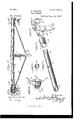
- Figure 1 is a vertical section of so much of a truck, together with a portion of a car-body and brake-beams, as will serve to illustrate the application of my invention.
- Figure 2 is an enlarged detached perspective view of a brake-beam with the brake-heads and with a combined suspension hanger and reliefspring embodying features of my invention.
- FIG. 3 is an enlarged plan View of a brakebeam with brake-shoes, parts broken away to more clearly illustrate the construction and combination.
- Figs. 4, 5, 6, and 7 are detached perspective views in alinement of the compression member of the beam, (parts broken out,) an end cap therefor, a brake: head, and an end plate which forms the seat of the nut on the outer end of the tension-rod, said parts appearing, respectively, in the order named, commencing at the left of the views.
- Fig. 8 is a transverse section of the brake-beam, (tension-rod omitted,) taken on the line 00 :r, Fig. 3, looking inthe direction of the arrow, showing the means by which the head is rendered automatically adj ustable; and
- Fig. 9 is an end View of the compression member of the beam.
- My invention relates generally to the construction of brake-beams, and has several objects in view, viz: first, such a suspension of the beam that finger-guards maybe dispensed with; second, such a construction as will combine in one element the functions of the release-spring and third suspensionhangcr, which features tend to simplify the construction, reduce the costs, and enhance the safety and durability of the beam; thirdly, to obtain a construction which will secure a simple and efficient automaticallyadjustable brake-head, and, finally, in the ease of brake-beams having a tubular compression member and tension-rod in combination to so construct and combine said elements of the structure as to avoid any slotting of the compression member,whereby the strength of the structure as a whole will be conserved and tendency of the compression member to buckle or give down near the brake-head will be avoided.
- I provide the beam with a center pin or finger or projection, which engages an arm supported from the truck, and such a construction or its equivalent embodies one feature of my invention.
- beams said finger is preferably formed on or made an extension of the post or strut.
- a second feature of my invention embraces the combination, with a beam havinga center pin or finger, of a springarm or resilient support therefor.
- the head In the combination of brake-heads and In case of trussed IOO brake-beams it has been found desirable that the head should be capable of a limited rotation on the beam, so that it may adapt itself to the wheel and the throw of the head be thereafter maintained until the conditions become changed.
- a fourth feature of my invention embraces the longitudinal indentation of the ends of the tubular compression member on or substantially on the line of intersection therewith of the tension-rod, or, in other words, I form the hollow compression member with U shaped depressions which extend from the ends thereof inwardly toward one another, said depressions gradually decreasing in depth until they merge into the periphery of the tubular compression member, whereby without loss of substance or strength provision is made for the passage of the ends of the intersecting tension member of the structure.
- FIG. 1 of the drawings A indicates a carbody beneath which and supporting the same is the usual truck with wheels B, bolster C, and channel-irons D.
- E E indicate brake-beams embodying my invention, suspended from the truck by centrally-located arms F.
- the spring-arm F which is supported from the truck between the wheels, is preferably of rectangular shape, having its vertical section f slotted, as at 1, to receive a pin 1 or finger placed centrally of the beam, whereby the lateral or endwise movement of the beam is prevented and the finger-guards, heretofore employed to prevent said movement of the beam and the wearing of the beam by the wheel-flange, may be dispensed with.
- the arm F may be rigid throughout, and if it is only to perform the function of a third suspension-hanger it may likewise be rigid throughout,as the back-and-forth movement of the beam to and from the wheels can be readily secured by the play of the pin 1 in slot 1 or by well-known equivalents; but
- the centrallyplaced arm 1* should also perform the function of a releasespring, and therefore the movement of the beam independently of the arm should be prevented by means of a pin 1", which passes through center pin 1 or its equivalent, and at least the vertical member f of the arm F should be resilient, and preferably the whole arm F is of resilient material.
- the beams chosen for illustration are, as before noted, of the class known as hollow trussed brake-beams, 2 being the compression member; 3, the post or strut; 4 at, brakeheads, and 5 the tension member.
- the compression member 2 may be either solid, a slotted tube, or a welded tube so far as some of the combinations hereinafter claimed are concerned, but if of a closed or welded tubular structure I indent the ends thereof longitudinally, as at 2, on the lines of intersection of the tension member 5 with the compression member, so that said compression member will be provided with alined U-shaped depressions 2, extending from the ends of said tube inwardly toward one another and toward the longitudinal center of said beam, which depressions gradually taper and decrease in depth until they reach the original surface or periphery of the tube, and
- cap 6 indicates an end cap, (or cup,) one of which will be used on each end of a hollow compression member, said cap (or cup) perforated for the passage of the tension-rod, as at 6, and provided with a flange or collar 7 to limit the inward movement of the brake-head and provide an inner bearing therefor, which collar may be cut away or recessed, as at 7, to receive a lug or projection 4 on the inner face of brake-head 4.
- t indicates the brake-head, which may be of any of the many well-known types, provided it is formed with a socket adapted to the end and cross section of the compression member (beam)with which itis to be used, and
- this strut or post 3 terminates in a pin or finger 1, which passes through the slot 1 in the end of arm F and through which passes securing-pin 1 as hereinbefore pointed out.
- the beam is then hung by means of the usual end (or lateral) hangers either to the car-body or the truck-bolster, as the case may be, and the projecting central pin or finger 1 (whether the same be on the compression member or beam proper or on the end of the strut or post) is passed through the slot 1 in the end of arm F and secured by inserting pin 1 or in an equivalent manner.
- the finger or pin l may be located directly on the beam proper, 2, and this may be done even with a trussed beam, but is not desirable. Itwill also be evident that in case of a solid compression member the bearing collar 7 may be formed directly on the beam proper, 2, and it will be equally apparent that the confining notch or recess 7 may be shifted from collar 7 to the end plate 8, and limit-lug 4i and notch or recess '7 may change places, none of which changes would constitute more than alternate constructions for the preferable form which has been herein shown and described.
- the arm F supports the beam centrally and prevents its lateral or endwise play when the brakes are oif. By its elasticity it will yield to allow the beam to approach the wheels when the brakes are applied,while its resiliency will withdraw the beam and hold the brakes away from the wheels when the brakes are off.
- a brake-beam the combination with the beam of a collar or bearing for the brakehead, a brake-head rotatable on said beam, an end plate which confines the brake-head, and a tension-rod which confines the end plate and forces the head against the bearing or collar of the beam; substantially as and for the purposes specified.
- a compression member having a collar or bear ing for the brakehead, an end plate, brakehead rotatable on the compression member and interposed between the collar thereof and the end plate, one of said parts having a limit-lug and a second having a recess in which the limit-lug rests, and a tension-rod which confines the parts and forces the head against the bearing-collar on the compression member; substantially as and for the purposes specified.
- a tubular compression member having at its end depressions or indented channels for the reception of the ends of the tension member; substantially as and for the purposes specified.
- a tubular compression member having indentations at its ends for the reception of the ends of the tension member, brakeheads, and end plates, which confine the brake-heads and through which the ends of 120 the tension-rod pass; substantially as and for the purposes specified.
- a trussed brake-beam having a strut or post and a tension-rod
- the combination therewith of a tubular beam having at its 125 ends indentations to receive the ends of the tension-rod, end caps (or cups) which include the ends of the compression member and the ends of the tension member, and end plates through which the ends of the tension mem- 1 o ber pass; substantially as and for the purposes specified.
Landscapes
- Engineering & Computer Science (AREA)
- Mechanical Engineering (AREA)
- Braking Arrangements (AREA)
Description
LU e e h s W e e h .s 2 Ym m B RY K FA ,R B m d o M 0 W Patented Jan. 1-9," 1897.
w i l meooea a how m auto? V 331;; Her/14m THE Noams PETEIIi Cc.. mom LITN 2 Sheets-Sheet 2. J. PARLEY.
BRAKE BEAM.
(No Model.)
No. 575,420. Patented Jan. 19, 1897.
NITED STATES PATENT OFFICE.
JAMES FARLEY, OF WVAUKESI-IA, IVISCONSIN, ASSIGNOR TO THE CHICAGO RAILWAY EQUIPMENT COMPANY, OF CHICAGO, ILLINOIS.
BRAKE-BEAM.-
SPEGIFIGATION forming part of Letters Patent No. 575,420, dated January 19, 1897. Application filed July 25, 1896. Serial No. 600,511. (No model.)
To all whom it may concern.-
Be it known that I, JAMES FARLEY, a citizen of the United States, residing at Vaukesha, in the county of Waukesha, State of Wisconsin, have invented certain new and useful Improvements in Brake-Beams; and I hereby declare the following to be a full, clear, and exact description of the same, reference being had to the accompanying drawings, wherein Figure 1 is a vertical section of so much of a truck, together with a portion of a car-body and brake-beams, as will serve to illustrate the application of my invention. Fig. 2 is an enlarged detached perspective view of a brake-beam with the brake-heads and with a combined suspension hanger and reliefspring embodying features of my invention. Fig. 3 is an enlarged plan View of a brakebeam with brake-shoes, parts broken away to more clearly illustrate the construction and combination. Figs. 4, 5, 6, and 7 are detached perspective views in alinement of the compression member of the beam, (parts broken out,) an end cap therefor, a brake: head, and an end plate which forms the seat of the nut on the outer end of the tension-rod, said parts appearing, respectively, in the order named, commencing at the left of the views. Fig. 8 is a transverse section of the brake-beam, (tension-rod omitted,) taken on the line 00 :r, Fig. 3, looking inthe direction of the arrow, showing the means by which the head is rendered automatically adj ustable; and Fig. 9 is an end View of the compression member of the beam.
Like symbols refer to like parts wherever they occur.
My invention relates generally to the construction of brake-beams, and has several objects in view, viz: first, such a suspension of the beam that finger-guards maybe dispensed with; second, such a construction as will combine in one element the functions of the release-spring and third suspensionhangcr, which features tend to simplify the construction, reduce the costs, and enhance the safety and durability of the beam; thirdly, to obtain a construction which will secure a simple and efficient automaticallyadjustable brake-head, and, finally, in the ease of brake-beams having a tubular compression member and tension-rod in combination to so construct and combine said elements of the structure as to avoid any slotting of the compression member,whereby the strength of the structure as a whole will be conserved and tendency of the compression member to buckle or give down near the brake-head will be avoided.
It will be noted that some of the above points are applicable to break-beams generally, others to trussed beams only, and still others only to trussed beams having tubular compression members. In order, therefore, to fully illustrate my invention, I have chosen to show a hollow trussed brake-beam, but do not intend the same as a matter of limitatiou.
In carrying out the first object of my invention I provide the beam with a center pin or finger or projection, which engages an arm supported from the truck, and such a construction or its equivalent embodies one feature of my invention. beams said finger is preferably formed on or made an extension of the post or strut.
lVith trussed brake-beams or like beams wherein the weight is forward of the compression member (or beam proper) it is common to use a central or third suspensionhanger, and in all beams it is common to combine therewith release-springs or equivalent means for holding the brake-beam and brakeshoes off the wheels. Therefore to simplify the construction I prefer to make the arm which is supported on or extends from. the truck a spring-arm and to slot the lower end thereof for the passage of the center pin or finger of the brake-beam, whereby said arm not only prevents the lateral play of the beam, thus dispensing with guard-fingers thereon, but will yieldingly support the beam centrally, so that it has the function of a third suspension-hanger, and if resilient and properly connected with the beam said arm will also perform the function of the usual reliefspring. Therefore a second feature of my invention embraces the combination, with a beam havinga center pin or finger, of a springarm or resilient support therefor.
In the combination of brake-heads and In case of trussed IOO brake-beams it has been found desirable that the head should be capable of a limited rotation on the beam, so that it may adapt itself to the wheel and the throw of the head be thereafter maintained until the conditions become changed. To secure said automatic adjustment of the head upon the beam, I confine the brake-head between a bearing or collar upon the beam and an end plate through which the tension-rod passes, whereby the head is yieldingly gripped, and I provide a limit-lug and slot therefor to confine the rotation of the brake-head on the beam within prescribed bounds, and such a construction or its equivalent embodies a third feature of my invention.
A fourth feature of my invention embraces the longitudinal indentation of the ends of the tubular compression member on or substantially on the line of intersection therewith of the tension-rod, or, in other words, I form the hollow compression member with U shaped depressions which extend from the ends thereof inwardly toward one another, said depressions gradually decreasing in depth until they merge into the periphery of the tubular compression member, whereby without loss of substance or strength provision is made for the passage of the ends of the intersecting tension member of the structure.
There are other minor features of invention, all as will hereinafter more fully appear.
I will now proceed to describe my invention more fully, so that others skilled in the art to which it appertains may apply the same.
In Fig. 1 of the drawings, A indicates a carbody beneath which and supporting the same is the usual truck with wheels B, bolster C, and channel-irons D.
E E indicate brake-beams embodying my invention, suspended from the truck by centrally-located arms F.
For purposes of illustration an inside-hung brake-beam having its end hangers supported from the truck is shown at the left of Fig. 1, while an outside-hung brake-beam having its end hangers supported from the car-body is shown at the right of said View.
The spring-arm F, which is supported from the truck between the wheels, is preferably of rectangular shape, having its vertical section f slotted, as at 1, to receive a pin 1 or finger placed centrally of the beam, whereby the lateral or endwise movement of the beam is prevented and the finger-guards, heretofore employed to prevent said movement of the beam and the wearing of the beam by the wheel-flange, may be dispensed with. It is evident that if it is only desired to prevent the lateralor endwise play of the beam above specified the arm F may be rigid throughout, and if it is only to perform the function of a third suspension-hanger it may likewise be rigid throughout,as the back-and-forth movement of the beam to and from the wheels can be readily secured by the play of the pin 1 in slot 1 or by well-known equivalents; but
I prefer that the centrallyplaced arm 1* should also perform the function of a releasespring, and therefore the movement of the beam independently of the arm should be prevented by means of a pin 1", which passes through center pin 1 or its equivalent, and at least the vertical member f of the arm F should be resilient, and preferably the whole arm F is of resilient material.
The beams chosen for illustration are, as before noted, of the class known as hollow trussed brake-beams, 2 being the compression member; 3, the post or strut; 4 at, brakeheads, and 5 the tension member.
The compression member 2 may be either solid, a slotted tube, or a welded tube so far as some of the combinations hereinafter claimed are concerned, but if of a closed or welded tubular structure I indent the ends thereof longitudinally, as at 2, on the lines of intersection of the tension member 5 with the compression member, so that said compression member will be provided with alined U-shaped depressions 2, extending from the ends of said tube inwardly toward one another and toward the longitudinal center of said beam, which depressions gradually taper and decrease in depth until they reach the original surface or periphery of the tube, and
thus afford a seat or passage for the ends of v the tension member 5 without destroying the integrity of the walls of the compression member.
6 indicates an end cap, (or cup,) one of which will be used on each end of a hollow compression member, said cap (or cup) perforated for the passage of the tension-rod, as at 6, and provided with a flange or collar 7 to limit the inward movement of the brake-head and provide an inner bearing therefor, which collar may be cut away or recessed, as at 7, to receive a lug or projection 4 on the inner face of brake-head 4.
t indicates the brake-head, which may be of any of the many well-known types, provided it is formed with a socket adapted to the end and cross section of the compression member (beam)with which itis to be used, and
provided also that it has upon one face a limit-lug to engage in the recess 7 of collar 7.
8 indicates an end plate, one for each end of the beam, adapted to fit upon the outer end of the compression member 2 and perforated, as at 8, for the passage of the end of the tension-rod 5. The outer face of said plate 8 is inclined to the axis of the compression member, as at 8 to afford a seat for the nut 5 on the end of the tension member.
3 indicates the post or strut, which may be of the usual pattern, with diagonal lever-slot (right or left, as the case may be) and pinholes 3 for the fulcrum-pin of the lever. The
nose of this strut or post 3 terminates in a pin or finger 1, which passes through the slot 1 in the end of arm F and through which passes securing-pin 1 as hereinbefore pointed out.
The several parts of the structure being IOC IIC
. specified will be combined-or set up to form a beam-as follows: The post or strut 3 having been arranged centrally of the compres sion member 2 and in line with the longitudinal indentations or depressions 2, the end caps 6 are next placed on the ends of the compression member with the notches or recesses on the same side as the post or strut 3, then the ends of the tension-rod are passed inside the caps and through the perforations 6 thereof, after which the brake-heads tare slipped on the end caps 6 with the lugs 4 rest ing in the notches or recesses 7 of collars 7 and finally the end plates 8 are put in place and the parts drawn home by means of the nuts 5, sufficientforce being used to give a slight camber to compression member 2, if such camber is desired.
The beam is then hung by means of the usual end (or lateral) hangers either to the car-body or the truck-bolster, as the case may be, and the projecting central pin or finger 1 (whether the same be on the compression member or beam proper or on the end of the strut or post) is passed through the slot 1 in the end of arm F and secured by inserting pin 1 or in an equivalent manner.
It will be evident to any one skilled in the art that in case the beam is not a trussed beam the finger or pin l may be located directly on the beam proper, 2, and this may be done even with a trussed beam, but is not desirable. Itwill also be evident that in case of a solid compression member the bearing collar 7 may be formed directly on the beam proper, 2, and it will be equally apparent that the confining notch or recess 7 may be shifted from collar 7 to the end plate 8, and limit-lug 4i and notch or recess '7 may change places, none of which changes would constitute more than alternate constructions for the preferable form which has been herein shown and described.
I11 operation the arm F supports the beam centrally and prevents its lateral or endwise play when the brakes are oif. By its elasticity it will yield to allow the beam to approach the wheels when the brakes are applied,while its resiliency will withdraw the beam and hold the brakes away from the wheels when the brakes are off. The clamping effect of the tension-rod 5 and end plates 8 and collar 7 will hold the brake-head against accidental rotation when the head shall have automatically acquired the proper throw from contact with the wheel in braking, and the limit-lug will prevent the head from being carried too far around either up or down, and the indented seats in the ends of the compression member for the passage of the ends of the tension member will increase the strength of the beam at the points of greatest torsional strain and help the structure to resist buckling and breaking forces.
Having thus described my invention, what I claim, and desire to secure by Letters Patent, is-
1. The combination with a brake-beam having a projecting pin or finger, of a slotted support with which the projecting pin or finger of the beam engages; substantially as and for the purposes specified.
2. The combination with a brake-beam having a projecting pin or finger, of a resilient slotted support with which the projecting pin or finger of the beam engages; substantially as and for the purposes specified.
The combination with a suspended brakebeam, of a resilient arm or support therefor which engages the beam intermediate of its hangers, said resilient arm being supported from the truck between the axles, whereby the endwise movement of the beam is prevented and the brakes are held off; substantially as and for the purposes specified.
4:. In a brake-beam the combination with the beam of a collar or bearing for the brakehead, a brake-head rotatable on said beam, an end plate which confines the brake-head, and a tension-rod which confines the end plate and forces the head against the bearing or collar of the beam; substantially as and for the purposes specified.
5. In a brake-beam, the combination of a compression member having a collar or bear ing for the brakehead, an end plate, brakehead rotatable on the compression member and interposed between the collar thereof and the end plate, one of said parts having a limit-lug and a second having a recess in which the limit-lug rests, and a tension-rod which confines the parts and forces the head against the bearing-collar on the compression member; substantially as and for the purposes specified.
6. In a trussed brake-beam having a strut or post and a tension-rod, the combination therewith of a tubular compression member having at its end depressions or indented channels for the reception of the ends of the tension member; substantially as and for the purposes specified.
7. In a trussed brake-beam having a strut or post and a tension-rod, the combination therewith of a tubular compression member having indentations at its ends for the reception of the ends of the tension member, brakeheads, and end plates, which confine the brake-heads and through which the ends of 120 the tension-rod pass; substantially as and for the purposes specified.
8. In a trussed brake-beam, having a strut or post and a tension-rod, the combination therewith of a tubular beam having at its 125 ends indentations to receive the ends of the tension-rod, end caps (or cups) which include the ends of the compression member and the ends of the tension member, and end plates through which the ends of the tension mem- 1 o ber pass; substantially as and for the purposes specified.
10 spring of rectangular form supported from the truck between the axles, substantially as and for the purposes specified.
In testimony whereof I affix my signature,
in presence of two witnesses, this 23d day of July, 1896.
JAMES FARLEY.
Witnesses:
H. A. TULLAR, E. T. WALKER.
Publications (1)
| Publication Number | Publication Date |
|---|---|
| US575420A true US575420A (en) | 1897-01-19 |
Family
ID=2644112
Family Applications (1)
| Application Number | Title | Priority Date | Filing Date |
|---|---|---|---|
| US575420D Expired - Lifetime US575420A (en) | Brake-beam |
Country Status (1)
| Country | Link |
|---|---|
| US (1) | US575420A (en) |
Cited By (6)
| Publication number | Priority date | Publication date | Assignee | Title |
|---|---|---|---|---|
| US5947236A (en) * | 1997-06-13 | 1999-09-07 | New York Air Brake Corporation | Truck mounted brake for standard and premium ride trucks |
| US6155387A (en) * | 1997-06-13 | 2000-12-05 | New York Air Brake Corporation | Truck mounted brake beam and method of manufacturing |
| US6176354B1 (en) | 1997-06-13 | 2001-01-23 | New York Air Brake Corporation | Truck mounted brake beam with removable brake heads |
| US6332515B1 (en) | 1997-06-13 | 2001-12-25 | New York Air Brake Corp. | Truck mounted brake beam |
| USD497571S1 (en) | 2003-06-05 | 2004-10-26 | New York Air Brake Corporation | Railcar beam |
| USD497837S1 (en) | 2003-06-05 | 2004-11-02 | New York Air Brake Corporation | Railcar beam |
-
0
- US US575420D patent/US575420A/en not_active Expired - Lifetime
Cited By (6)
| Publication number | Priority date | Publication date | Assignee | Title |
|---|---|---|---|---|
| US5947236A (en) * | 1997-06-13 | 1999-09-07 | New York Air Brake Corporation | Truck mounted brake for standard and premium ride trucks |
| US6155387A (en) * | 1997-06-13 | 2000-12-05 | New York Air Brake Corporation | Truck mounted brake beam and method of manufacturing |
| US6176354B1 (en) | 1997-06-13 | 2001-01-23 | New York Air Brake Corporation | Truck mounted brake beam with removable brake heads |
| US6332515B1 (en) | 1997-06-13 | 2001-12-25 | New York Air Brake Corp. | Truck mounted brake beam |
| USD497571S1 (en) | 2003-06-05 | 2004-10-26 | New York Air Brake Corporation | Railcar beam |
| USD497837S1 (en) | 2003-06-05 | 2004-11-02 | New York Air Brake Corporation | Railcar beam |
Similar Documents
| Publication | Publication Date | Title |
|---|---|---|
| US568044A (en) | Brake- beam | |
| US345093A (en) | Car-brake | |
| US494709A (en) | Brake-beam | |
| US2310195A (en) | Brake rigging and/or railway car truck | |
| US1073812A (en) | Truck. | |
| US461776A (en) | Trussed bar for railway-brakes | |
| US2069353A (en) | Safety hanger for brake beams | |
| US604456A (en) | Luther c | |
| US696641A (en) | Car-truck. | |
| US497514A (en) | Car-brake | |
| US902138A (en) | Railway brake-beam. | |
| US1318240A (en) | Spring-beam and spbing-seat fob cab-trucks | |
| US1988235A (en) | Emergency supporting means for brake mechanism | |
| US799117A (en) | Car-brake. | |
| US721564A (en) | Trussed brake-beam. | |
| US558208A (en) | Car-brake | |
| US607421A (en) | Luther c | |
| US614862A (en) | Railroad-car brake | |
| US2375727A (en) | Car truck | |
| US606756A (en) | Luther c | |
| US579496A (en) | Brake-beam | |
| US144537A (en) | Improvement in car-brakes | |
| US762286A (en) | Bolster or other beam for car-trucks. | |
| US570057A (en) | Brake-beam | |
| US158426A (en) | Improvement in car-brakes |