US5747073A - Apparatus for producing composite cylinders - Google Patents
Apparatus for producing composite cylinders Download PDFInfo
- Publication number
- US5747073A US5747073A US08/865,742 US86574297A US5747073A US 5747073 A US5747073 A US 5747073A US 86574297 A US86574297 A US 86574297A US 5747073 A US5747073 A US 5747073A
- Authority
- US
- United States
- Prior art keywords
- molding tool
- cylinder
- powdered
- molding
- tool
- Prior art date
- Legal status (The legal status is an assumption and is not a legal conclusion. Google has not performed a legal analysis and makes no representation as to the accuracy of the status listed.)
- Expired - Fee Related
Links
- 239000002131 composite material Substances 0.000 title abstract description 12
- 238000000465 moulding Methods 0.000 claims description 70
- 239000012255 powdered metal Substances 0.000 claims description 30
- 239000000463 material Substances 0.000 claims description 14
- 238000004140 cleaning Methods 0.000 claims description 5
- 238000005245 sintering Methods 0.000 claims description 5
- 238000006073 displacement reaction Methods 0.000 claims 4
- 238000000034 method Methods 0.000 abstract description 13
- 239000007769 metal material Substances 0.000 abstract description 4
- XEEYBQQBJWHFJM-UHFFFAOYSA-N Iron Chemical compound [Fe] XEEYBQQBJWHFJM-UHFFFAOYSA-N 0.000 description 69
- 239000010949 copper Substances 0.000 description 33
- 239000000843 powder Substances 0.000 description 24
- 229910052742 iron Inorganic materials 0.000 description 22
- 229910052751 metal Inorganic materials 0.000 description 19
- 239000002184 metal Substances 0.000 description 19
- 150000002739 metals Chemical class 0.000 description 14
- 229910052802 copper Inorganic materials 0.000 description 10
- 210000000078 claw Anatomy 0.000 description 9
- 238000010586 diagram Methods 0.000 description 8
- 229910052782 aluminium Inorganic materials 0.000 description 7
- 238000002485 combustion reaction Methods 0.000 description 7
- RYGMFSIKBFXOCR-UHFFFAOYSA-N Copper Chemical compound [Cu] RYGMFSIKBFXOCR-UHFFFAOYSA-N 0.000 description 5
- XAGFODPZIPBFFR-UHFFFAOYSA-N aluminium Chemical compound [Al] XAGFODPZIPBFFR-UHFFFAOYSA-N 0.000 description 5
- 230000007246 mechanism Effects 0.000 description 4
- 229910000838 Al alloy Inorganic materials 0.000 description 3
- 229910001018 Cast iron Inorganic materials 0.000 description 3
- 238000004519 manufacturing process Methods 0.000 description 3
- 238000005192 partition Methods 0.000 description 3
- 239000012254 powdered material Substances 0.000 description 3
- 238000003825 pressing Methods 0.000 description 3
- 239000012530 fluid Substances 0.000 description 2
- 239000012256 powdered iron Substances 0.000 description 2
- 229910045601 alloy Inorganic materials 0.000 description 1
- 239000000956 alloy Substances 0.000 description 1
- 238000013459 approach Methods 0.000 description 1
- 238000005056 compaction Methods 0.000 description 1
- 150000001875 compounds Chemical class 0.000 description 1
- 238000005429 filling process Methods 0.000 description 1
- 238000003780 insertion Methods 0.000 description 1
- 230000037431 insertion Effects 0.000 description 1
- 238000003754 machining Methods 0.000 description 1
- 230000000717 retained effect Effects 0.000 description 1
- 238000010407 vacuum cleaning Methods 0.000 description 1
Images


Classifications
-
- B—PERFORMING OPERATIONS; TRANSPORTING
- B22—CASTING; POWDER METALLURGY
- B22F—WORKING METALLIC POWDER; MANUFACTURE OF ARTICLES FROM METALLIC POWDER; MAKING METALLIC POWDER; APPARATUS OR DEVICES SPECIALLY ADAPTED FOR METALLIC POWDER
- B22F7/00—Manufacture of composite layers, workpieces, or articles, comprising metallic powder, by sintering the powder, with or without compacting wherein at least one part is obtained by sintering or compression
- B22F7/06—Manufacture of composite layers, workpieces, or articles, comprising metallic powder, by sintering the powder, with or without compacting wherein at least one part is obtained by sintering or compression of composite workpieces or articles from parts, e.g. to form tipped tools
-
- B—PERFORMING OPERATIONS; TRANSPORTING
- B22—CASTING; POWDER METALLURGY
- B22F—WORKING METALLIC POWDER; MANUFACTURE OF ARTICLES FROM METALLIC POWDER; MAKING METALLIC POWDER; APPARATUS OR DEVICES SPECIALLY ADAPTED FOR METALLIC POWDER
- B22F3/00—Manufacture of workpieces or articles from metallic powder characterised by the manner of compacting or sintering; Apparatus specially adapted therefor ; Presses and furnaces
- B22F3/003—Apparatus, e.g. furnaces
-
- B—PERFORMING OPERATIONS; TRANSPORTING
- B22—CASTING; POWDER METALLURGY
- B22F—WORKING METALLIC POWDER; MANUFACTURE OF ARTICLES FROM METALLIC POWDER; MAKING METALLIC POWDER; APPARATUS OR DEVICES SPECIALLY ADAPTED FOR METALLIC POWDER
- B22F3/00—Manufacture of workpieces or articles from metallic powder characterised by the manner of compacting or sintering; Apparatus specially adapted therefor ; Presses and furnaces
- B22F3/004—Filling molds with powder
-
- B—PERFORMING OPERATIONS; TRANSPORTING
- B30—PRESSES
- B30B—PRESSES IN GENERAL
- B30B11/00—Presses specially adapted for forming shaped articles from material in particulate or plastic state, e.g. briquetting presses, tabletting presses
- B30B11/001—Presses specially adapted for forming shaped articles from material in particulate or plastic state, e.g. briquetting presses, tabletting presses using a flexible element, e.g. diaphragm, urged by fluid pressure; Isostatic presses
- B30B11/002—Isostatic press chambers; Press stands therefor
-
- B—PERFORMING OPERATIONS; TRANSPORTING
- B30—PRESSES
- B30B—PRESSES IN GENERAL
- B30B15/00—Details of, or accessories for, presses; Auxiliary measures in connection with pressing
- B30B15/30—Feeding material to presses
- B30B15/302—Feeding material in particulate or plastic state to moulding presses
- B30B15/304—Feeding material in particulate or plastic state to moulding presses by using feed frames or shoes with relative movement with regard to the mould or moulds
- B30B15/306—Feeding material in particulate or plastic state to moulding presses by using feed frames or shoes with relative movement with regard to the mould or moulds for multi-layer articles
Definitions
- This invention relates to apparatus for producing improved composite cylinders which have an inner layer of a first metallic material and an outer layer of a second metallic material. More particularly, the invention relates to apparatus for producing such composite cylinders which are suitable for use as cylinder liners in combustion engines or in bearing applications.
- the present invention eliminates the need for partitions and divider rings and provides a transitional bonding layer of material between inner and outer layers of the formed cylinder.
- the transitional bonding layer is characterized by being of the same materials that are bonded together to form the cylinder.
- Some internal combustion engines known in the art include engine blocks which are provided with a cylinder made of cast iron or an aluminum alloy cylinder into which a cylinder liner made of cast iron is inserted.
- an internal combustion engine cylinder should be comprised of a material that is highly resistant to wear, is light in weight, has a good thermal conductivity and good machinability.
- cast iron cylinders used as cylinder liners for internal combustion engines which are available in the prior art are relatively expensive, heavy in weight and have poor thermal conductivity, though it has relatively good wear resistance.
- aluminum alloy cylinder liners of the prior art while relatively light in weight and possessing a relatively good thermal conductivity is easily liable to wear. Copper, like the aluminum alloys, possesses good thermal conductivity but is also easily liable to wear.
- the cylinder of the present invention combines the best qualities of iron, i.e., durability and good wear resistance with the best qualities of aluminum or copper, i.e., lightweightness and good thermal conductivity to form a composite of iron and iron or iron and aluminum or a composite of iron and copper to provide a lightweight, wear resistant, relatively inexpensive cylinder having good thermal conductivity.
- Composites may also be formed of aluminum and copper, if desired.
- a salient feature of the present invention is that diverse metals are positioned in a pressure chamber in at least two contiguous, coaxial, annular columns. Pressure is then radially applied against the contiguous columns to provide a good bond between the diverse metallic columns to form a cylinder therefrom and the cylinder is then sintered at predetermined temperature for a predetermined time.
- the inner surface of the cylinder is formed of the more dense, wear resistant material which comes in contact with the piston rings, and the outer thermal conductive surface is formed from the lower density, a less expensive material.
- Fe.sub.(1) consists of powdered iron having a grain size of about -60 to -80 mesh and Fe.sub.(2) consists of iron having a grain size of about -100 to -150 mesh.
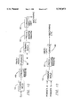
- FIG. 1 is an elevational diagrammatic view of the powdered metal compaction apparatus of the present invention.
- a powdered metal supply and feeder mechanism is shown positioned above a molding tool.
- FIG. 2 is a plan view of the apparatus of FIG. 1.
- FIG. 2a is an elevation view as seen along 2a-2a of FIG. 2 illustrating the lifting apparatus for raising the molding tool into the press wherein compacting of the adjacent metals in the molding tool is made to occur.
- the Figure also illustrates mechanism for moving the molding tool into position beneath the press.
- FIG. 2b is an enlarged elevational view of the actuator for moving the molding tool into position beneath the press.
- FIG. 2c is a sectional view taken along line 2c-2c of FIG. 2b.
- FIG. 3 is an exploded sectional view of the molding tool of the present invention partially inserted into a press for compacting the contiguous columns of metals in the molding tool.
- FIG. 4 is a sectional view of the press and molding tool in assembled relation.
- FIG. 5 is a sectional exploded view of the molding tool.
- FIGS. 6 and 7 are partial sectional views of the powder feeding device and illustrates the method for loading the powdered metals into the molding tool in contiguous columns.
- FIG. 8 is a sectional view of a cylinder formed according to the principles of the present invention.
- FIG. 9 is a block diagram of the method for forming a cylinder of two dissimilar iron based powdered metals wherein the iron based powdered metals are dissimilar in that they are of different grain size.
- FIG. 10 is a block diagram for forming a cylinder of a preformed sintered Fe cylinder and Al powder.
- FIG. 11 is a block diagram for forming a cylinder of a preformed sintered Fe cylinder and Cu powder.
- FIG. 12 is a block diagram for forming a cylinder of a preformed sintered Cu cylinder and Al powder.
- FIG. 13 is a block diagram for forming a cylinder of powder Cu and powder Al.
- FIGS. 14 is a block diagram for forming a cylinder of powdered Fe and powdered Cu.
- apparatus 10 (FIGS. 1 and 2) is provided for moving one of a plurality of molding tools 14 which is positioned on sliding trays 19 carried on a turntable 16 (rotatable by any of many rotation imparting means known in the art) beneath a powdered metal feeding device 22 so that the feeding device 22 can feed powdered metal into a cavity 12 of molding tool 14.
- the apparatus 10 is shown, in FIG. 2, to include around the periphery of turntable 16, a powder filling station 11, a pressurizing station 13, a cylinder removal station 15 and a mold cleaning station 17.
- the powder filling station 11 is the position wherein powdered metal is poured into the cavity of the molding tool 14.
- the turntable rotates the filled molding tool to the pressurization station where pressure is applied against the molding tool by a press 45 to form a cylinder.
- Turntable 16 then rotates the compacted cylinder to the cylinder removal station 15 where the formed cylinder is removed from the molding tool to be placed in a furnace.
- the empty molding tool is then positioned at cleaning station 17 where a vacuum device removes any remaining powders from the molding tool.
- FIG. 1 illustrates the use of a pair of hoppers 18 and 20 for discretely storing a pair of diverse powdered metals for reasons explained hereinbelow.
- the apparatus 10 may be automatically controlled.
- FIG. 8 illustrates a cylinder 21 produced by the apparatus method of the present invention.
- the cylinder includes a cylinder wall which is formed of two layers 8 and 9.
- the layers may comprise, in one embodiment, two iron based powders which may differ in grain size.
- the grain size of the first iron based material (Fe.sub.(1)) may, by way of example, be on the order of -60 mesh and the grain size of the second iron based material (Fe.sub.(2)) may be on the order of -100 mesh.
- a bonding layer comprised of the powdered metals only is formed between the two layers and mechanically lock the layers together since small portions of each powdered metal will be integrated into each other (grain interlocking) during the compacting and sintering cycles of the forming procedure.
- feed device 22 includes a valve assembly 44 comprising a plurality of spaced concentric annular walls 24, 26 and 28 forming powder receiving cavities 30 and 32 therebetween.
- Wall 28 is formed by a stem 46 having a lower conical portion 42 which is provided with lower surface 43 for engagement with an upper surface 23 of a mandrel 36.
- Inner wall 26 is provided with a lower conical portion 27 having a lower surface 29 which engages an inner lower surface 39 of outer wall 24.
- Molding tool 14 (FIGS. 3, 4 and 5), includes a base 76 which supports the mandrel 36 thereon.
- An elastomeric forming mold 37 member, having a cavity 35 therein, is mounted to an annular support member 41.
- Base 76, mandrel 36, and support member 41 are mounted for vertical movement in forming mold member 37.
- the molding tool 14 is disposed for insertion into a press 45 after being filled by powdered metals from device 22.
- the press 45 and the molding tool 14 is somewhat similar to that disclosed in U.S. Pat. No. 4,564,352, issued to Ola Pettersson on Jan. 14, 1986 for "Apparatus For Compensating Axial Strain In An Isostatic Press" and incorporated herein by reference.
- FIG. 5 illustrates molding tool 14 and FIGS. 3 and 4 illustrate press 45 of the present invention which includes a cylindrical jacket 50 with a fixed end structure 52.
- the jacket 50 On its inside, the jacket 50 has an elastomeric annular jacket 56 and an annular hydraulic chamber 58 is provided between jacket 50 and elastomeric jacket 56.
- the chamber 58 is pressurized via a pressurization and vent line 60.
- the molding tool 14 With the molding tool 14 filled with two diverse metals such as Fe.sub.(1) and Fe.sub.(2) as discussed supra, it is inserted into press 45 as seen in FIG. 4, and pressure (typically hydraulic) is directed into chamber 58 through member 60 to apply pressure against forming mold 37 which in turn exerts pressure against the powdered metals carried in annular chamber 35 (mold cavity) between elastomeric member 37 and mandrel 36.
- pressure typically hydraulic
- chamber 58 to apply pressure against forming mold 37 which in turn exerts pressure against the powdered metals carried in annular chamber 35 (mold cavity) between elastomeric member 37 and mandrel 36.
- the pressure compacts the two different metals into the configuration shown in FIG. 8.
- FIGS. 6 and 7 illustrate the filling procedure.
- the conical end surface 43 of stem 46 is positioned against the top surface 23 of mandrel 36.
- the tool guide support member 41 and forming mold member 37 of molding tool 14 is raised upwardly to a point wherein an inner annular surface 78 of the tool guide support member 41 is at a predetermined distance (designated by the letter X) from the bottom surface 79 of vertically movable sleeve or wall 24, at which time filling begins.
- a lifting assembly 31 is provided at the powder filling station 11 (FIGS. 1 and 2) and includes a pair of movable arms 33 (FIG. 1) having gripping surfaces 34 thereon to grip the tool guide support member 41 and forming mold member 37 for vertical movement thereof relative to the mandrel 36 and the mandrel base 76 which remains on the turntable.
- An actuator 40 (FIG. 1) is provided to vertically move the arms 34.
- An actuator 47 is provided to move the gripping surfaces 34 into gripping engagement with the movable guide support member 41 and forming mold member 37. While fluid actuators 40 and 47 are disclosed as the fluidic actuating mechanisms, it is to be understood that electric motors may be utilized, if desired.
- the filled mold is then placed in the pressure vessel 45 and then pressurized by hydraulic pressure flowing through fill valve 60 into the hydraulic chamber 58 thereby radially acting the two columns of metal together into a single mass in the form of a cylinder (FIG. 8).
- the compacting pressure is on the order of 50,000-90,000 PSI. (Preferably on the order of about 60,000 PSI).
- FIG. 1 illustrates two hoppers for filling the molding tool. It is important, according to the principles of the present invention, that the metals be positioned in the mold cavity at a predetermined orientation wherein the powdered metals form contiguous, concentric, annular columns.
- each tool tray 19 includes an extending portion 51 having a tray claw 54 (FIGS. 2a-2b) on the distal end thereon.
- Claw 54 is formed by an upper portion 55 and lower portion 57 having a space 59 therebetween.
- 2c lower portion 57 is provided with a cutout portion 61.
- An actuator 73 (hydraulically actuated solenoid, controlled piston or an electric motor) having an arm 63 provided with an annular enlarged shoulder 65 disposed on the distal end thereof is provided to move molding tool 14 underneath the press 45.
- the actuator arm 63 pushes the tool tray onto an elevatable press table 75 under the press 45.
- the tool tray 19 remains in this extended position during the pressing operation.
- the press table 75 is elevated by actuator 49 to lift the molding tool into press 45. After pressing is completed, the tool tray is lowered.
- the lower portion 59 of claw 54 is provided with a cut-out portion 61.
- the cut-out portion 61 moves downwardly over arm 63 and shoulder 65 into the tool claw 54.
- the enlarged shoulder 65 engages the interior surfaces of upper and lower members 54 and 57 to provide linear movement to the tool tray and the molding tool.
- Continued rotation of table 16 moves the shoulder 65 from the space between upper portion 55 and lower portion 57 of claw 54 to permit the molding tool to be moved to the next station 13.
- the tool tray remains in the same position relative to table 16 by being retained in guide members 5 as seen in FIG. 2, and shoulder 65 slides through one side of claw 54 and out the other side of claw 54 responsive to rotation of table 16.
- the turntable is then rotated to the cylinder removal station 15 where the cylinder is removed from the molding tool.
- an inflatable member 53 (FIG. 1) is moved downwardly by a vertically movable support structure 55 and is inserted inside the cylinder and inflated so as to grip the inner wall of the cylinder. Member 53 is then raised for removal from the molding tool.
- the support structure may be vertically movable by a hydraulic actuator 65 or electric motor, as desired.
- the turntable then rotates the molding tool to cleaning station 17 where a vacuum cleaning apparatus 57 (FIG. 1) is lowered by a vertically movable support 66 to vacuum out any remaining powdered metals.
- the vertically movable support 66 may be movable by fluid actuators or electric motors, as desired.
- the formed cylinder is placed in a furnace 49 FIG. 9) where it is sintered at temperatures in the range of 1950° F. to 2400° F. for a period of 20-60 minutes. After sintering, the cylinder is then cooled to room temperature after which any desired or required machining is accomplished.
- the method for forming a cylinder made of Fe powder and a preformed sintered Al cylinder is illustrated in the block diagram of FIG. 10.
- powdered Fe is placed in forming mold 14 and compacted by press 45 at about 50,000-90,000 PSI (preferably 60,000 PSI).
- the formed, compacted cylinder is then placed in furnace 49 where it is sintered at about 1950°-2400° F. for about 20-60 minutes.
- the cylinder After the cylinder has been sintered and allowed to cool, it is then placed back in the mold 14 and powdered aluminum is added to form two contiguous columns. One column is the sintered Fe cylinder and the second column is the powdered Al.
- the mold is then placed in the press and is pressurized at about 40,000-70,000 PSI to compact the powdered Al and to bond and interlock the powdered Al to the formed Fe cylinder.
- the cylinder is then placed in furnace 49 where it is sintered at about 1050°-1150° F. for 20-60 minutes. It is to be understood that the powdered Al may be bonded to the interior or exterior surfaces of the iron cylinders, as desired.
- the method for forming a cylinder of powdered iron and a preformed sintered Cu cylinder is illustrated in the block diagram of FIG. 11.
- powdered Fe is placed in forming mold 14 and compacted by press 45 at about 50,000-90,000 PSI, (preferably 60,000 PSI).
- the formed, compacted cylinder is then placed in furnace 49 where it is sintered at about 1950°-2400° F. for about 20-60 minutes.
- the cylinder After the cylinder has been sintered and allowed to cool, it is then placed in the mold 14 and powdered Cu is added to form two contiguous columns.
- One column is the sintered Fe cylinder and the second column is the powdered Cu.
- the mold is then placed in the press 45 and is pressurized at about 40,000-70,000 PSI (preferably 60,000 PSI) to compact the powdered Cu and to bond the powdered Cu to the formed Fe cylinder.
- the cylinder is then placed in furnace 49 where it is sintered at about 1500°-1650° F. (preferably 1550° F.) for 10-20 minutes. It is to be understood that the powdered Cu may be bonded to the interior or exterior surfaces of the iron cylinder, as desired.
- Aluminum and Copper may be combined to form an Al/Cu cylinder in the manner and by the apparatus described herein (FIG. 12).
- Cu powder is placed in forming mold 14 and compacted by press 45 at about 40,000-70,000 PSI (preferably 60,000 PSI).
- the compacted cylinder is then sintered at about 1500°-1650° F.
- the compacted, and sintered cylinder is then cooled and placed in molding tool 14 and powdered Al is then added to form two contiguous columns.
- One column is the sintered Cu cylinder and the second column is powdered Al.
- the molding tool 14 is then placed in the press and pressurized at about 40,000-70,000 PSI (preferably 60,000 PSI) to compact the powdered Al and to bond the powdered Al to the Cu cylinder.
- the cylinder is then placed in furnace 49 where it is sintered at about 1050°-1150° F. (preferably 1100° F.) for about 10-15 minutes. It is to be understood that the powdered Al may be bonded to the interior or exterior surface of the Cu cylinder, as desired.
- Powdered Al and powdered Cu may also be resorted to forming an Al/Cu cylinder instead of relying on the formed Cu cylinder as one component (FIG. 13). In such a case it is necessary to fill the molding tool 14 with diverse contiguous annular columns of the powder Al and powdered Cu as discussed above.
- the powdered Al and powdered Cu columns are then compacted in press 45 at a pressure of 40,000-70,000 PSI (preferably 60,000 PSI) and is then sintered at about 1050°-1150° F. for about 10-20 minutes to complete the bonding process. The sintered cylinder is then allowed to cool.
- Powdered Fe and powdered Cu may be utilized in forming a Fe/Cu cylinder, if desired. This is accomplished by filling the molding tool 14 with diverse contiguous columns of Fe and Cu in the manner discussed above. The powdered Fe and Cu columns are then compacted in press 45 at a pressure of 50,000-70,000 PSI (preferably 60,000 PSI) and then sintered at about 1050°-1150° F. for a period of 20-60 minutes. The sintered cylinder is then allowed to cool.
- the cylinder may be made in various configurations.
- the external wall of the cylinder may be curved, if desired.
- configurations such as spaced ridges, flanges, criss-cross patterns, or spiral patterns may be provided on the external wall of the cylinder. To provide such configurations it is only necessary to provide the inner surface of the elastomeric member of the forming mold with the inverse configurations of the desired shapes.
Landscapes
- Engineering & Computer Science (AREA)
- Mechanical Engineering (AREA)
- Manufacturing & Machinery (AREA)
- Physics & Mathematics (AREA)
- Fluid Mechanics (AREA)
- Chemical & Material Sciences (AREA)
- Composite Materials (AREA)
- Materials Engineering (AREA)
- Powder Metallurgy (AREA)
Abstract
Apparatus is disclosed for producing composite cylinders having cylinder walls comprised of two adjacent diverse layers of metal material which are bonded together by application of radial forces thereto and then sintered to complete the bonding process. Mechanical locking of the layers is achieved by grain interlocking between the two layers of metal material.
Description
This is a continuation of application Ser. No. 08/549,426, filed Oct. 27, 1995 now abandoned.
This invention relates to apparatus for producing improved composite cylinders which have an inner layer of a first metallic material and an outer layer of a second metallic material. More particularly, the invention relates to apparatus for producing such composite cylinders which are suitable for use as cylinder liners in combustion engines or in bearing applications.
It is known in the prior art to form composite metal cylinders by positioning first and second powdered materials in a mold cavity with the powdered materials in coaxial relation and having a divider ring or partition between the two powdered materials. The powders are then isostatically pressed to form a cylinder having inner and outer walls comprised of different materials. A prior art patent which discloses such composite metal cylinders is U.S. Pat. No. 4,721,598 issued on Jan. 26, 1988, to Peter W. Lee.
Another prior art patent which discloses such composite metal cylinders is U.S. Pat. No. 5,069,866 issued on Dec. 3, 1991 to Ragnar Ekbom for "Method For Manufacturing A Compound" first and second powders and upon being isostatically compacted and sintered the partition material becomes a part of the finished cylinders. No transitional layer of bonding material comprised of an intermixture of the compacted powders is used.
The present invention eliminates the need for partitions and divider rings and provides a transitional bonding layer of material between inner and outer layers of the formed cylinder. The transitional bonding layer is characterized by being of the same materials that are bonded together to form the cylinder.
Some internal combustion engines known in the art include engine blocks which are provided with a cylinder made of cast iron or an aluminum alloy cylinder into which a cylinder liner made of cast iron is inserted.
It has been well recognized that an internal combustion engine cylinder should be comprised of a material that is highly resistant to wear, is light in weight, has a good thermal conductivity and good machinability. However, as is well known, that cast iron cylinders used as cylinder liners for internal combustion engines which are available in the prior art are relatively expensive, heavy in weight and have poor thermal conductivity, though it has relatively good wear resistance. Also, aluminum alloy cylinder liners of the prior art, while relatively light in weight and possessing a relatively good thermal conductivity is easily liable to wear. Copper, like the aluminum alloys, possesses good thermal conductivity but is also easily liable to wear.
The cylinder of the present invention combines the best qualities of iron, i.e., durability and good wear resistance with the best qualities of aluminum or copper, i.e., lightweightness and good thermal conductivity to form a composite of iron and iron or iron and aluminum or a composite of iron and copper to provide a lightweight, wear resistant, relatively inexpensive cylinder having good thermal conductivity. Composites may also be formed of aluminum and copper, if desired.
It is an object of the present invention to provide a powdered metal composite cylinder.
It is a further object of the present invention to provide such a cylinder in the shape of a cylinder liner for internal combustion engines.
It is still a further object of the present invention to provide apparatus for manufacturing such composite powdered metal cylinders.
It is yet a further object of the present invention to provide a method for manufacturing such powdered metal cylinder liners.
A salient feature of the present invention is that diverse metals are positioned in a pressure chamber in at least two contiguous, coaxial, annular columns. Pressure is then radially applied against the contiguous columns to provide a good bond between the diverse metallic columns to form a cylinder therefrom and the cylinder is then sintered at predetermined temperature for a predetermined time.
In the case of cylinder liners for internal combustion engines, it can be readily appreciated that the inner surface of the cylinder is formed of the more dense, wear resistant material which comes in contact with the piston rings, and the outer thermal conductive surface is formed from the lower density, a less expensive material.
Some typical combinations of metals as used herein include Al/Fe, Al/Cu, Cu/Fe, or Fe.sub.(1) /Fe.sub.(2) where Fe.sub.(1) consists of powdered iron having a grain size of about -60 to -80 mesh and Fe.sub.(2) consists of iron having a grain size of about -100 to -150 mesh.
FIG. 1 is an elevational diagrammatic view of the powdered metal compaction apparatus of the present invention. A powdered metal supply and feeder mechanism is shown positioned above a molding tool.
FIG. 2 is a plan view of the apparatus of FIG. 1.
FIG. 2a is an elevation view as seen along 2a-2a of FIG. 2 illustrating the lifting apparatus for raising the molding tool into the press wherein compacting of the adjacent metals in the molding tool is made to occur. The Figure also illustrates mechanism for moving the molding tool into position beneath the press.
FIG. 2b is an enlarged elevational view of the actuator for moving the molding tool into position beneath the press.
FIG. 2c is a sectional view taken along line 2c-2c of FIG. 2b.
FIG. 3 is an exploded sectional view of the molding tool of the present invention partially inserted into a press for compacting the contiguous columns of metals in the molding tool.
FIG. 4 is a sectional view of the press and molding tool in assembled relation.
FIG. 5 is a sectional exploded view of the molding tool.
FIGS. 6 and 7 are partial sectional views of the powder feeding device and illustrates the method for loading the powdered metals into the molding tool in contiguous columns.
FIG. 8 is a sectional view of a cylinder formed according to the principles of the present invention.
FIG. 9 is a block diagram of the method for forming a cylinder of two dissimilar iron based powdered metals wherein the iron based powdered metals are dissimilar in that they are of different grain size.
FIG. 10 is a block diagram for forming a cylinder of a preformed sintered Fe cylinder and Al powder.
FIG. 11 is a block diagram for forming a cylinder of a preformed sintered Fe cylinder and Cu powder.
FIG. 12 is a block diagram for forming a cylinder of a preformed sintered Cu cylinder and Al powder.
FIG. 13 is a block diagram for forming a cylinder of powder Cu and powder Al.
FIGS. 14 is a block diagram for forming a cylinder of powdered Fe and powdered Cu.
In carrying out the principles of the present invention, apparatus 10 (FIGS. 1 and 2) is provided for moving one of a plurality of molding tools 14 which is positioned on sliding trays 19 carried on a turntable 16 (rotatable by any of many rotation imparting means known in the art) beneath a powdered metal feeding device 22 so that the feeding device 22 can feed powdered metal into a cavity 12 of molding tool 14.
The apparatus 10 is shown, in FIG. 2, to include around the periphery of turntable 16, a powder filling station 11, a pressurizing station 13, a cylinder removal station 15 and a mold cleaning station 17. The powder filling station 11 is the position wherein powdered metal is poured into the cavity of the molding tool 14. The turntable rotates the filled molding tool to the pressurization station where pressure is applied against the molding tool by a press 45 to form a cylinder. Turntable 16 then rotates the compacted cylinder to the cylinder removal station 15 where the formed cylinder is removed from the molding tool to be placed in a furnace. Upon continued rotation of turntable 16, the empty molding tool is then positioned at cleaning station 17 where a vacuum device removes any remaining powders from the molding tool.
FIG. 1 illustrates the use of a pair of hoppers 18 and 20 for discretely storing a pair of diverse powdered metals for reasons explained hereinbelow. However, in certain applications only one powdered metal is used and if only one powdered metal is used (for reasons explained hereinbelow) in forming the cylinder of the present invention, only one hopper is necessary. The apparatus 10 may be automatically controlled.
FIG. 8 illustrates a cylinder 21 produced by the apparatus method of the present invention. The cylinder includes a cylinder wall which is formed of two layers 8 and 9. The layers may comprise, in one embodiment, two iron based powders which may differ in grain size. The grain size of the first iron based material (Fe.sub.(1)) may, by way of example, be on the order of -60 mesh and the grain size of the second iron based material (Fe.sub.(2)) may be on the order of -100 mesh. When forming a cylinder of Fe.sub.(1) and Fe.sub.(2) in accordance to the principles of the present invention, it is necessary to feed the two different materials into annular cavity 12 of molding tool 14 in such a manner as to form two unmixed, annular, powder columns in coaxial, contiguous relation around a mandrel which forms a part of the molding tool 14 (see FIGS. 6 and 7). Since larger mesh size iron powder is generally less expensive than the more dense smaller mesh size iron powder, a less expensive iron cylinder is made by combining the two iron based powders. When the cylinder is used as a cylinder liner in internal combustion engines, the more dense layer is provided on the interior of the cylinder. A bonding layer comprised of the powdered metals only is formed between the two layers and mechanically lock the layers together since small portions of each powdered metal will be integrated into each other (grain interlocking) during the compacting and sintering cycles of the forming procedure.
As seen in FIGS. 6 and 7, feed device 22 includes a valve assembly 44 comprising a plurality of spaced concentric annular walls 24, 26 and 28 forming powder receiving cavities 30 and 32 therebetween. Wall 28 is formed by a stem 46 having a lower conical portion 42 which is provided with lower surface 43 for engagement with an upper surface 23 of a mandrel 36. Inner wall 26 is provided with a lower conical portion 27 having a lower surface 29 which engages an inner lower surface 39 of outer wall 24.
FIG. 5 illustrates molding tool 14 and FIGS. 3 and 4 illustrate press 45 of the present invention which includes a cylindrical jacket 50 with a fixed end structure 52. On its inside, the jacket 50 has an elastomeric annular jacket 56 and an annular hydraulic chamber 58 is provided between jacket 50 and elastomeric jacket 56. The chamber 58 is pressurized via a pressurization and vent line 60.
With the molding tool 14 filled with two diverse metals such as Fe.sub.(1) and Fe.sub.(2) as discussed supra, it is inserted into press 45 as seen in FIG. 4, and pressure (typically hydraulic) is directed into chamber 58 through member 60 to apply pressure against forming mold 37 which in turn exerts pressure against the powdered metals carried in annular chamber 35 (mold cavity) between elastomeric member 37 and mandrel 36. The pressure compacts the two different metals into the configuration shown in FIG. 8.
FIGS. 6 and 7 illustrate the filling procedure. As seen in FIG. 6 which illustrates the beginning of the filling process, the conical end surface 43 of stem 46 is positioned against the top surface 23 of mandrel 36. The tool guide support member 41 and forming mold member 37 of molding tool 14 is raised upwardly to a point wherein an inner annular surface 78 of the tool guide support member 41 is at a predetermined distance (designated by the letter X) from the bottom surface 79 of vertically movable sleeve or wall 24, at which time filling begins.
To raise the tool guide support member 41 and forming mold member 37 to this position a lifting assembly 31 is provided at the powder filling station 11 (FIGS. 1 and 2) and includes a pair of movable arms 33 (FIG. 1) having gripping surfaces 34 thereon to grip the tool guide support member 41 and forming mold member 37 for vertical movement thereof relative to the mandrel 36 and the mandrel base 76 which remains on the turntable. An actuator 40 (FIG. 1) is provided to vertically move the arms 34. An actuator 47 is provided to move the gripping surfaces 34 into gripping engagement with the movable guide support member 41 and forming mold member 37. While fluid actuators 40 and 47 are disclosed as the fluidic actuating mechanisms, it is to be understood that electric motors may be utilized, if desired.
While in the position shown in FIG. 6, vertically movable outer sleeve 24 is moved upwardly by an actuator 81 at the same time that tool guide member 41 is moved downwardly by mechanism 31. The powders are loaded into the cavity 35 in side-by-side, annular, contiguous relation as the tool guide support member 41 is moved downwardly carrying the forming mold 37 with it, until the configuration illustrated in FIG. 7 is reached. Powder flow is then terminated.
The filled mold is then placed in the pressure vessel 45 and then pressurized by hydraulic pressure flowing through fill valve 60 into the hydraulic chamber 58 thereby radially acting the two columns of metal together into a single mass in the form of a cylinder (FIG. 8). For Fe.sub.(1) and Fe.sub.(2) the compacting pressure is on the order of 50,000-90,000 PSI. (Preferably on the order of about 60,000 PSI).
In the operation of the apparatus, a molding tool 14 is positioned at the powder filling station 11 where it is filled with powdered metal. FIG. 1 illustrates two hoppers for filling the molding tool. It is important, according to the principles of the present invention, that the metals be positioned in the mold cavity at a predetermined orientation wherein the powdered metals form contiguous, concentric, annular columns.
To place the filled mold in the pressure vessel the turntable in rotated to be positioned at the pressurization station 13 beneath the pressure vessel 45. As seen in FIG. 2, a plurality of tool trays 19 are positioned in equally spaced relation in guide members 5 on the table 16. The molding tools 14 are placed on the tool trays 19. After one of the molding tools 14 has been loaded with the diverse metals at station 11, table 16 is rotated to position the loaded molding tool and tool tray 19 under the press 45. As seen in FIGS. 2, 2a and 2b each tool tray 19 includes an extending portion 51 having a tray claw 54 (FIGS. 2a-2b) on the distal end thereon. Claw 54 is formed by an upper portion 55 and lower portion 57 having a space 59 therebetween. As seen in FIG. 2c lower portion 57 is provided with a cutout portion 61. An actuator 73 (hydraulically actuated solenoid, controlled piston or an electric motor) having an arm 63 provided with an annular enlarged shoulder 65 disposed on the distal end thereof is provided to move molding tool 14 underneath the press 45. As the molding tool rotates around the table and approaches the pressing station 13 the shoulder 65 moves into the space 57 of the claw 54. The actuator arm 63 pushes the tool tray onto an elevatable press table 75 under the press 45. The tool tray 19 remains in this extended position during the pressing operation. To position the molding tool into press 45, the press table 75 is elevated by actuator 49 to lift the molding tool into press 45. After pressing is completed, the tool tray is lowered. To permit the tool tray to be lowered and to be rejoined with arm 63, the lower portion 59 of claw 54 is provided with a cut-out portion 61. The cut-out portion 61 moves downwardly over arm 63 and shoulder 65 into the tool claw 54. While in tool claw 54 the enlarged shoulder 65 engages the interior surfaces of upper and lower members 54 and 57 to provide linear movement to the tool tray and the molding tool. Continued rotation of table 16 moves the shoulder 65 from the space between upper portion 55 and lower portion 57 of claw 54 to permit the molding tool to be moved to the next station 13. The tool tray remains in the same position relative to table 16 by being retained in guide members 5 as seen in FIG. 2, and shoulder 65 slides through one side of claw 54 and out the other side of claw 54 responsive to rotation of table 16.
The turntable is then rotated to the cylinder removal station 15 where the cylinder is removed from the molding tool. To remove the cylinder, an inflatable member 53 (FIG. 1) is moved downwardly by a vertically movable support structure 55 and is inserted inside the cylinder and inflated so as to grip the inner wall of the cylinder. Member 53 is then raised for removal from the molding tool. The support structure may be vertically movable by a hydraulic actuator 65 or electric motor, as desired. The turntable then rotates the molding tool to cleaning station 17 where a vacuum cleaning apparatus 57 (FIG. 1) is lowered by a vertically movable support 66 to vacuum out any remaining powdered metals. The vertically movable support 66 may be movable by fluid actuators or electric motors, as desired.
After the compacting process is completed (in the case of Fe.sub.(1) and Fe.sub.(2)) the formed cylinder is placed in a furnace 49 FIG. 9) where it is sintered at temperatures in the range of 1950° F. to 2400° F. for a period of 20-60 minutes. After sintering, the cylinder is then cooled to room temperature after which any desired or required machining is accomplished.
While the above discussion has been directed to powdered Fe.sub.(1) and Fe.sub.(2) it is to be understood that combinations of other metal powders may be resorted to. Of course, the sintering temperatures and forming pressures resorted to depends on the choice of metals to be compacted and sintered.
The method for forming a cylinder made of Fe powder and a preformed sintered Al cylinder is illustrated in the block diagram of FIG. 10. As seen in FIG. 10, powdered Fe is placed in forming mold 14 and compacted by press 45 at about 50,000-90,000 PSI (preferably 60,000 PSI). The formed, compacted cylinder is then placed in furnace 49 where it is sintered at about 1950°-2400° F. for about 20-60 minutes.
After the cylinder has been sintered and allowed to cool, it is then placed back in the mold 14 and powdered aluminum is added to form two contiguous columns. One column is the sintered Fe cylinder and the second column is the powdered Al. The mold is then placed in the press and is pressurized at about 40,000-70,000 PSI to compact the powdered Al and to bond and interlock the powdered Al to the formed Fe cylinder. The cylinder is then placed in furnace 49 where it is sintered at about 1050°-1150° F. for 20-60 minutes. It is to be understood that the powdered Al may be bonded to the interior or exterior surfaces of the iron cylinders, as desired.
The method for forming a cylinder of powdered iron and a preformed sintered Cu cylinder is illustrated in the block diagram of FIG. 11. As seen in FIG. 11, powdered Fe is placed in forming mold 14 and compacted by press 45 at about 50,000-90,000 PSI, (preferably 60,000 PSI). The formed, compacted cylinder is then placed in furnace 49 where it is sintered at about 1950°-2400° F. for about 20-60 minutes. After the cylinder has been sintered and allowed to cool, it is then placed in the mold 14 and powdered Cu is added to form two contiguous columns. One column is the sintered Fe cylinder and the second column is the powdered Cu. The mold is then placed in the press 45 and is pressurized at about 40,000-70,000 PSI (preferably 60,000 PSI) to compact the powdered Cu and to bond the powdered Cu to the formed Fe cylinder. The cylinder is then placed in furnace 49 where it is sintered at about 1500°-1650° F. (preferably 1550° F.) for 10-20 minutes. It is to be understood that the powdered Cu may be bonded to the interior or exterior surfaces of the iron cylinder, as desired.
It is to be understood that although the above discussion has been directed to the combination of an iron based metals other than iron based metals may be resorted to. Aluminum and Copper, for example, may be combined to form an Al/Cu cylinder in the manner and by the apparatus described herein (FIG. 12). When forming such an Al/Cu cylinder, Cu powder is placed in forming mold 14 and compacted by press 45 at about 40,000-70,000 PSI (preferably 60,000 PSI). The compacted cylinder is then sintered at about 1500°-1650° F. The compacted, and sintered cylinder is then cooled and placed in molding tool 14 and powdered Al is then added to form two contiguous columns. One column is the sintered Cu cylinder and the second column is powdered Al. The molding tool 14 is then placed in the press and pressurized at about 40,000-70,000 PSI (preferably 60,000 PSI) to compact the powdered Al and to bond the powdered Al to the Cu cylinder. The cylinder is then placed in furnace 49 where it is sintered at about 1050°-1150° F. (preferably 1100° F.) for about 10-15 minutes. It is to be understood that the powdered Al may be bonded to the interior or exterior surface of the Cu cylinder, as desired.
Powdered Al and powdered Cu may also be resorted to forming an Al/Cu cylinder instead of relying on the formed Cu cylinder as one component (FIG. 13). In such a case it is necessary to fill the molding tool 14 with diverse contiguous annular columns of the powder Al and powdered Cu as discussed above. The powdered Al and powdered Cu columns are then compacted in press 45 at a pressure of 40,000-70,000 PSI (preferably 60,000 PSI) and is then sintered at about 1050°-1150° F. for about 10-20 minutes to complete the bonding process. The sintered cylinder is then allowed to cool.
Powdered Fe and powdered Cu (FIG. 14) may be utilized in forming a Fe/Cu cylinder, if desired. This is accomplished by filling the molding tool 14 with diverse contiguous columns of Fe and Cu in the manner discussed above. The powdered Fe and Cu columns are then compacted in press 45 at a pressure of 50,000-70,000 PSI (preferably 60,000 PSI) and then sintered at about 1050°-1150° F. for a period of 20-60 minutes. The sintered cylinder is then allowed to cool.
It is to be understood that the cylinder may be made in various configurations. The external wall of the cylinder may be curved, if desired. Also configurations such as spaced ridges, flanges, criss-cross patterns, or spiral patterns may be provided on the external wall of the cylinder. To provide such configurations it is only necessary to provide the inner surface of the elastomeric member of the forming mold with the inverse configurations of the desired shapes.
It is to be further understood that although Cu, Fe, Al etc. has been used in describing the metals of the cylinder, various alloys of these metals may be resorted to, if desired.
It is yet to be further understood that in each of the above described embodiments of the present invention mechanical bonding between the contiguous metal columns are achieved because of grain interlocking between the two adjacent columns responsive to the compacting and sintering process.
Claims (9)
1. Apparatus for forming a cylindrical member from powdered metal material comprising:
a molding tool having a mandrel and a pressurizable elastomeric member mounted circumferentially about said mandrel to form a single annular forming chamber;
a rotatable table having a plurality of molding tool support positions spaced therearound for sequentially rotating through a molding tool filling station at which said molding tool is filled with said powdered metal material, a pressurization station at which said molding tool is pressurized to bond said powdered metal materials and thereby form said cylindrical member, a removal station at which said cylindrical member is removed from said molding tool for sintering thereof, and a cleaning station at which said molding tool is cleaned;
a pressure vessel mounted in spaced relation above said table;
first support means carried at each said molding tool support position for supporting a said molding tool thereon on said table;
second support means mounted adjacent said table at said pressurization station to receive and support said molding tool thereon;
first molding tool displacement means disposed for horizontal reciprocal movement to move said molding tool from said table to said second support means and back to said table;
actuator means for reciprocal movement of said first molding tool displacement means; and
second molding tool displacement means for vertical reciprocal movement of said molding tool at said pressurization station to raise said molding tool into said pressure vessel for pressurization of said molding tool and to lower said molding tool down from said pressure vessel, whereby said first molding tool displacement means moves said molding back onto said table so that said molding tool may be sequentially moved to said tool removal and cleaning stations.
2. Apparatus as in claim 1 including feeder means for feeding said powdered metal into said annular chamber of said molding tool.
3. Apparatus as in claim 2 wherein said first support member includes a support plate for supporting said molding tool thereon, said support plate having a first arm extending therefrom, said actuator means having a second arm extending therefrom, said first and second arms being disposed for releasably attached relation.
4. Apparatus as in claim 3 including means for attaching said first and second arms in the releasably attached relation.
5. Apparatus as in claim 1 including feeder means for feeding said powdered metal into said chamber of said molding tool.
6. Apparatus as in claim 5 wherein said feeder means is positioned above said table, said apparatus including means for vertically raising said molding tool from a first downwardly retracted position to an upwardly extended position adjacent said feeder means and back to said retracted position.
7. Apparatus as in claim 2 wherein said feeder means includes a valve assembly including a first outer annular wall, a second intermediate annular wall and a third inner annular wall, said walls enclosing first and second powdered metal receiving cavities therebetween.
8. Apparatus as in claim 7 including means for vertically moving said first outer annular wall to permit said powdered metals in said first and second cavities to flow from said valve assembly.
9. Apparatus as in claim 8 including means for varying the height of said molding chamber during flow of said powdered metals therein to produce a pair of contiguous powdered metal columns.
Priority Applications (1)
| Application Number | Priority Date | Filing Date | Title |
|---|---|---|---|
| US08/865,742 US5747073A (en) | 1995-10-27 | 1997-05-30 | Apparatus for producing composite cylinders |
Applications Claiming Priority (2)
| Application Number | Priority Date | Filing Date | Title |
|---|---|---|---|
| US54942695A | 1995-10-27 | 1995-10-27 | |
| US08/865,742 US5747073A (en) | 1995-10-27 | 1997-05-30 | Apparatus for producing composite cylinders |
Related Parent Applications (1)
| Application Number | Title | Priority Date | Filing Date |
|---|---|---|---|
| US54942695A Continuation | 1995-10-27 | 1995-10-27 |
Publications (1)
| Publication Number | Publication Date |
|---|---|
| US5747073A true US5747073A (en) | 1998-05-05 |
Family
ID=24192994
Family Applications (1)
| Application Number | Title | Priority Date | Filing Date |
|---|---|---|---|
| US08/865,742 Expired - Fee Related US5747073A (en) | 1995-10-27 | 1997-05-30 | Apparatus for producing composite cylinders |
Country Status (1)
| Country | Link |
|---|---|
| US (1) | US5747073A (en) |
Cited By (13)
| Publication number | Priority date | Publication date | Assignee | Title |
|---|---|---|---|---|
| US6612827B1 (en) * | 1999-05-14 | 2003-09-02 | Wilhelm Fette Gmbh | Apparatus for the manufacture of compacts |
| US6881048B1 (en) * | 1999-03-31 | 2005-04-19 | Sumitomo Coal Mining Co., Ltd. | Apparatus for automatically loading powder material into a mold |
| US20050201885A1 (en) * | 2001-09-14 | 2005-09-15 | Iap Research, Inc. | System and method for loading a plurality of powder materials in a compaction press |
| US20060286194A1 (en) * | 2005-06-11 | 2006-12-21 | Sms Meer Gmbh | Powder press |
| US20070071632A1 (en) * | 2003-11-28 | 2007-03-29 | Commissariat A L'energie Atomique | Device for filling a mould with a powder or a mixture of powders |
| US20080197525A1 (en) * | 2005-05-23 | 2008-08-21 | Fine Technics Co., Ltd. | Apparatus and Method for Supplying Powder Quantitatively and Material Supplying Apparatus Including the Apparatus for Supplying Powder |
| EP2052848A1 (en) * | 2007-10-27 | 2009-04-29 | Joint Solar Silicon GmbH & Co. KG | Manufacture of moulded blanks from high-grade silicon |
| US20100086429A1 (en) * | 2006-09-22 | 2010-04-08 | Campbell Timothy M | Thin walled powder metal component manufacturing |
| JP2014105364A (en) * | 2012-11-28 | 2014-06-09 | Toyota Motor Corp | Molding apparatus, and molding method |
| EP2842664A4 (en) * | 2012-04-23 | 2016-01-20 | Aida Eng Ltd | Device for high-density molding and method for high-density molding of mixed powder, and high-density three-layer-structured powder compact |
| US20180058368A1 (en) * | 2015-03-31 | 2018-03-01 | Achates Power, Inc. | Cylinder liner for an opposed-piston engine |
| CN108972385A (en) * | 2018-05-30 | 2018-12-11 | 安徽佑开科技有限公司 | A kind of automatic feeding device of grinding wheel die |
| US11203053B2 (en) | 2019-10-03 | 2021-12-21 | Shyam Newar | Peripheral combination hydraulic press to forge and method of manufacturing thereof |
Citations (8)
| Publication number | Priority date | Publication date | Assignee | Title |
|---|---|---|---|---|
| US3193900A (en) * | 1963-09-30 | 1965-07-13 | Pacific Clay Products | Apparatus for manufacturing clay pipe |
| US3264388A (en) * | 1962-02-02 | 1966-08-02 | Kaiser Aluminium Chem Corp | Method of continuously hot pressing powdered refractory material |
| US3339234A (en) * | 1964-01-24 | 1967-09-05 | Multifol Patentverwert Ag | Apparatus for making laminated articles |
| US3677674A (en) * | 1971-03-09 | 1972-07-18 | Nat Forge Co | High production isostatic molding device |
| US3887317A (en) * | 1973-06-06 | 1975-06-03 | Jurid Werke Gmbh | Pressing apparatus |
| US4370120A (en) * | 1978-11-28 | 1983-01-25 | Foster Robert D | Compacting press with expandable body |
| US4564352A (en) * | 1982-11-09 | 1986-01-14 | Kb Cold Isostatic Press Systems Cips | Apparatus for compensating axial strain in an isostatic press |
| US4728475A (en) * | 1985-09-27 | 1988-03-01 | Neumunstersche Maschinen-Und Apparatebau Gmbh | Method of and device for admixing finely divided dye stuff into a synthetic granulate |
-
1997
- 1997-05-30 US US08/865,742 patent/US5747073A/en not_active Expired - Fee Related
Patent Citations (8)
| Publication number | Priority date | Publication date | Assignee | Title |
|---|---|---|---|---|
| US3264388A (en) * | 1962-02-02 | 1966-08-02 | Kaiser Aluminium Chem Corp | Method of continuously hot pressing powdered refractory material |
| US3193900A (en) * | 1963-09-30 | 1965-07-13 | Pacific Clay Products | Apparatus for manufacturing clay pipe |
| US3339234A (en) * | 1964-01-24 | 1967-09-05 | Multifol Patentverwert Ag | Apparatus for making laminated articles |
| US3677674A (en) * | 1971-03-09 | 1972-07-18 | Nat Forge Co | High production isostatic molding device |
| US3887317A (en) * | 1973-06-06 | 1975-06-03 | Jurid Werke Gmbh | Pressing apparatus |
| US4370120A (en) * | 1978-11-28 | 1983-01-25 | Foster Robert D | Compacting press with expandable body |
| US4564352A (en) * | 1982-11-09 | 1986-01-14 | Kb Cold Isostatic Press Systems Cips | Apparatus for compensating axial strain in an isostatic press |
| US4728475A (en) * | 1985-09-27 | 1988-03-01 | Neumunstersche Maschinen-Und Apparatebau Gmbh | Method of and device for admixing finely divided dye stuff into a synthetic granulate |
Cited By (22)
| Publication number | Priority date | Publication date | Assignee | Title |
|---|---|---|---|---|
| US6881048B1 (en) * | 1999-03-31 | 2005-04-19 | Sumitomo Coal Mining Co., Ltd. | Apparatus for automatically loading powder material into a mold |
| US20050089436A1 (en) * | 1999-03-31 | 2005-04-28 | Sumitomo Coal Mining Co., Ltd. | Method and apparatus for automatically loading powder material into a mold |
| US6612827B1 (en) * | 1999-05-14 | 2003-09-02 | Wilhelm Fette Gmbh | Apparatus for the manufacture of compacts |
| US7455509B2 (en) * | 2001-09-14 | 2008-11-25 | Iap Research, Inc. | System and method for loading a plurality of powder materials in a compaction press |
| US20050201885A1 (en) * | 2001-09-14 | 2005-09-15 | Iap Research, Inc. | System and method for loading a plurality of powder materials in a compaction press |
| US20070071632A1 (en) * | 2003-11-28 | 2007-03-29 | Commissariat A L'energie Atomique | Device for filling a mould with a powder or a mixture of powders |
| US7927091B2 (en) * | 2003-11-28 | 2011-04-19 | Commissariat A L'energie Atomique | Device for filling a mould with a powder or a mixture of powders |
| US8512022B2 (en) * | 2005-05-23 | 2013-08-20 | Fine Technics Co., Ltd. | Apparatus and method for supplying powder quantitatively and material supplying apparatus including the apparatus for supplying powder |
| US20110303697A1 (en) * | 2005-05-23 | 2011-12-15 | Fine Technics Co., Ltd | Apparatus and Method for Supplying Powder Quantitatively and Material Supplying Apparatus Including the Apparatus for Supplying Powder |
| US9333676B2 (en) | 2005-05-23 | 2016-05-10 | Fine Technics Co., Ltd. | Apparatus and method for supplying powder quantitatively and material supplying apparatus including the apparatus for supplying powder |
| US20080197525A1 (en) * | 2005-05-23 | 2008-08-21 | Fine Technics Co., Ltd. | Apparatus and Method for Supplying Powder Quantitatively and Material Supplying Apparatus Including the Apparatus for Supplying Powder |
| US7553145B2 (en) * | 2005-06-11 | 2009-06-30 | Sms Meer Gmbh | Powder press |
| US20060286194A1 (en) * | 2005-06-11 | 2006-12-21 | Sms Meer Gmbh | Powder press |
| US20100086429A1 (en) * | 2006-09-22 | 2010-04-08 | Campbell Timothy M | Thin walled powder metal component manufacturing |
| US8071016B2 (en) | 2006-09-22 | 2011-12-06 | Gkn Sinter Metals Llc | Thin walled powder metal component manufacturing |
| EP2052848A1 (en) * | 2007-10-27 | 2009-04-29 | Joint Solar Silicon GmbH & Co. KG | Manufacture of moulded blanks from high-grade silicon |
| WO2009053084A1 (en) * | 2007-10-27 | 2009-04-30 | Jssi Gmbh | Production of molded bodies from ultrapure silicon |
| EP2842664A4 (en) * | 2012-04-23 | 2016-01-20 | Aida Eng Ltd | Device for high-density molding and method for high-density molding of mixed powder, and high-density three-layer-structured powder compact |
| JP2014105364A (en) * | 2012-11-28 | 2014-06-09 | Toyota Motor Corp | Molding apparatus, and molding method |
| US20180058368A1 (en) * | 2015-03-31 | 2018-03-01 | Achates Power, Inc. | Cylinder liner for an opposed-piston engine |
| CN108972385A (en) * | 2018-05-30 | 2018-12-11 | 安徽佑开科技有限公司 | A kind of automatic feeding device of grinding wheel die |
| US11203053B2 (en) | 2019-10-03 | 2021-12-21 | Shyam Newar | Peripheral combination hydraulic press to forge and method of manufacturing thereof |
Similar Documents
| Publication | Publication Date | Title |
|---|---|---|
| US5747073A (en) | Apparatus for producing composite cylinders | |
| US5043123A (en) | Method and apparatus for manufacturing finished parts as composite bodies from pulverulent rolling materials | |
| US4472350A (en) | Method of making a compound valve seat | |
| US4673549A (en) | Method for preparing fully dense, near-net-shaped objects by powder metallurgy | |
| US4419413A (en) | Powder molding method and powder compression molded composite article having a rest-curve like boundary | |
| US4499048A (en) | Method of consolidating a metallic body | |
| US6120728A (en) | Method of making a component using a phased split die | |
| US3772935A (en) | Composite heavy-duty sintered powdered machine element | |
| US4054449A (en) | Process of making a composite heavy-duty powdered machine element | |
| US4721598A (en) | Powder metal composite and method of its manufacture | |
| JPH0773798B2 (en) | Method of forming permanent magnet body | |
| US4353155A (en) | Method for manufacturing composite powder metal parts | |
| US4352648A (en) | Powdered metal press and tooling therefor | |
| JPH09502767A (en) | Method and apparatus for manufacturing pressure-molded article | |
| EP1749254B1 (en) | Non-homogenous engine component formed by powder metallurgy | |
| US3550198A (en) | Apparatus for compacting finely-granulated materials | |
| CN110534332B (en) | Sintered magnet preparation method and pressure forming equipment thereof | |
| JPS5939499A (en) | Compacting method of green compact | |
| JP2008501906A (en) | Non-homogeneous engine components molded by powder metallurgy | |
| JPS60162702A (en) | Forming method of double-layered molding | |
| JP2019173088A (en) | Green compact molding device | |
| JP2007510060A (en) | Device receiving tool for calibration of workpiece and press with such device | |
| JP3617763B2 (en) | Molding method for green compacts used as sintered materials | |
| SU1694346A1 (en) | Method and apparatus for pressing hollow articles from powder | |
| EP1266746A2 (en) | Method of producing powder compacts and foil or film-like mold members for use in the method |
Legal Events
| Date | Code | Title | Description |
|---|---|---|---|
| AS | Assignment |
Owner name: TECSYN, INC., CANADA Free format text: ASSIGNMENT OF ASSIGNORS INTEREST;ASSIGNORS:PETTERSSON, BJORN OLA ALFONS;HOLMES, PATRICK W.;REEL/FRAME:008601/0828 Effective date: 19970520 |
|
| REMI | Maintenance fee reminder mailed | ||
| FEPP | Fee payment procedure |
Free format text: PAYOR NUMBER ASSIGNED (ORIGINAL EVENT CODE: ASPN); ENTITY STATUS OF PATENT OWNER: SMALL ENTITY |
|
| FPAY | Fee payment |
Year of fee payment: 4 |
|
| SULP | Surcharge for late payment | ||
| REMI | Maintenance fee reminder mailed | ||
| LAPS | Lapse for failure to pay maintenance fees | ||
| STCH | Information on status: patent discontinuation |
Free format text: PATENT EXPIRED DUE TO NONPAYMENT OF MAINTENANCE FEES UNDER 37 CFR 1.362 |
|
| FP | Lapsed due to failure to pay maintenance fee |
Effective date: 20060505 |