US5740474A - Apparatus for eliminating backlash in a zoom finder - Google Patents
Apparatus for eliminating backlash in a zoom finder Download PDFInfo
- Publication number
- US5740474A US5740474A US08/803,152 US80315297A US5740474A US 5740474 A US5740474 A US 5740474A US 80315297 A US80315297 A US 80315297A US 5740474 A US5740474 A US 5740474A
- Authority
- US
- United States
- Prior art keywords
- zoom
- cam
- cam surface
- variable power
- movable variable
- Prior art date
- Legal status (The legal status is an assumption and is not a legal conclusion. Google has not performed a legal analysis and makes no representation as to the accuracy of the status listed.)
- Expired - Lifetime
Links
Images
Classifications
-
- G—PHYSICS
- G02—OPTICS
- G02B—OPTICAL ELEMENTS, SYSTEMS OR APPARATUS
- G02B7/00—Mountings, adjusting means, or light-tight connections, for optical elements
- G02B7/02—Mountings, adjusting means, or light-tight connections, for optical elements for lenses
- G02B7/04—Mountings, adjusting means, or light-tight connections, for optical elements for lenses with mechanism for focusing or varying magnification
- G02B7/10—Mountings, adjusting means, or light-tight connections, for optical elements for lenses with mechanism for focusing or varying magnification by relative axial movement of several lenses, e.g. of varifocal objective lens
-
- G—PHYSICS
- G03—PHOTOGRAPHY; CINEMATOGRAPHY; ANALOGOUS TECHNIQUES USING WAVES OTHER THAN OPTICAL WAVES; ELECTROGRAPHY; HOLOGRAPHY
- G03B—APPARATUS OR ARRANGEMENTS FOR TAKING PHOTOGRAPHS OR FOR PROJECTING OR VIEWING THEM; APPARATUS OR ARRANGEMENTS EMPLOYING ANALOGOUS TECHNIQUES USING WAVES OTHER THAN OPTICAL WAVES; ACCESSORIES THEREFOR
- G03B13/00—Viewfinders; Focusing aids for cameras; Means for focusing for cameras; Autofocus systems for cameras
- G03B13/02—Viewfinders
- G03B13/10—Viewfinders adjusting viewfinders field
- G03B13/12—Viewfinders adjusting viewfinders field to compensate for change of camera lens or size of picture
Definitions
- the present invention relates to a zoom finder of a zoom compact camera, and more particularly relates to an apparatus for eliminating backlash withing a zoom finder mechanism.
- zoom compact are camera provided with a zoom finder which varies the field of view in association with a movement of a zoom-photographing lens.
- a movable zoom lens movable variable power lens
- a cam member which is driven in association with the movement of the zoom-photographing lens.
- a cam surface of the cam member is provided with a zoom section and a transfer section.
- the zoom section corresponds to a zooming section of the zoom-photographing lens in which the axial position of the movable variable power lens is varied.
- the transfer section corresponds to a transfer section of the zoom-photographing lens and extends from the zooming section to a retracted position where no movement of the movable variable power lens occurs. Since the cam member is driven in association with the movement of the zoom-photographing lens, backlash is inevitably produced in a gear mechanism or the like.
- the movement of the cam member due to the backlash tends to occur when the cam member (cam surface) moves from the transfer section to the zoom section during which a force in a direction perpendicular to the optical axis of the movable variable power lens is exerted on the cam member.
- the large movement of the movable variable power lens disturbs the field of view of the zoom finder.
- the basic concept of the present invention resides in that if the backlash of the cam member is eliminated before the cam surface of the cam member for the movable variable power lens transfers from the transfer section to the zooming portion, no accidental displacement of the movable variable power lens of the zoom finder occurs.
- an apparatus for eliminating a backlash in a zoom finder having a zoom-photographing lens which is movable between a zoom photographing section and a transfer section defined between the zoom photographing section and an accommodation position.
- a zoom finder is provided having at least one movable variable power lens which is supported to move in the optical axis direction.
- a cam member is provided with a cam surface engaged with the movable variable power lens and which is driven in association with the zoom-photographing lens.
- the cam surface is provided with a zoom section which corresponds to the zoom photographing section of the zoom-photographing lens, to vary the axial position of the movable variable power lens, and a transfer section corresponding to the transfer section of the zoom-photographing lens, where no movement of the movable variable power lens occurs.
- a backlash eliminating cam surface is provided separate from the cam surface on the cam member for the movable variable power lens.
- An oblique cam surface is provided on the backlash eliminating cam surface that is inclined with respect to a plane perpendicular to the optical axis of the movable variable power lens.
- the oblique cam surface is formed in a section corresponding to the zoom section side in the transfer section of the cam surface.
- a backlash eliminating member is continuously biased and pressed against the oblique cam surface to exert a drive force on the cam member in a direction perpendicular to the optical axis of the movable variable power lens.
- the backlash eliminating cam surface of the cam member be independently or separately provided, but also it can be made of a zoom strobe cam surface which is adapted to move the illumination angle varying member of a zoom strobe device.
- the backlash eliminating member can be made of the illumination angle varying member.
- the present invention can be applied to any cam member, for example, a rotatable cylindrical cam.
- an apparatus for eliminating backlash in a zoom finder of a zoom lens camera having a zoom finder having at least a pair of movable variable power lenses that are supported to move in an optical axis direction.
- a cylindrical cam is provided with a pair of cam surfaces that are engaged with the pair of movable variable power lenses and a backlash eliminating cam surface separate from the pair of cam surfaces for the movable variable power lenses.
- the cylindrical cam is rotated in association with a zooming operation of the zoom lens camera.
- Each of the pair of cam surfaces is provided with a zoom section to vary an axial position of the corresponding movable variable power lens, and a transfer section in which no movement of the movable variable power lenses occurs.
- the backlash eliminating cam surface is provided with an oblique cam surface that is inclined with respect to a plane perpendicular to the optical axis of the movable variable power lenses.
- the oblique cam surface is formed in a section corresponding to the zoom section side in the transfer section of the cam surface.
- a backlash eliminating member is continuously biased and pressed against the oblique cam surface to exert a rotational drive force on the cylindrical cam in a direction perpendicular to the optical axis of the movable variable power lens.
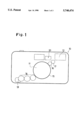
- FIG. 1 is a front elevational view of a zoom compact camera having a zoom finder according to the present invention
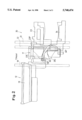
- FIG. 2 is a plan view of a cam drive mechanism of a zoom strobe device and a zoom finder
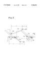
- FIG. 3 is a developed view of a cylindrical cam of the cam drive mechanism shown in FIG. 2.
- a zoom compact camera 10 is provided on a substantially central portion thereof with a zoom-photographing lens 11.
- a zoom strobe device 12 is provided on an upper right portion of the front surface of the camera body, and a zoom finder 20 is provided on the left side of the zoom strobe device 12.
- a rotation of a drive motor 13 is transmitted to the zoom-photographing lens 11 through a gear train 14, and is also transmitted to a cylindrical cam 17 through an outer peripheral gear 15 of the zoom-photographing lens 11 and a transmission gear 16.
- the cylindrical cam 17 simultaneously drives the zoom strobe device 12 and the zoom finder 20.
- the cylindrical cam 17 is constructed as shown in FIG. 2.
- the zoom strobe device 12, the zoom finder 20 and the cylindrical cam 17 are assembled into a finder/strobe assembly which is incorporated in the zoom compact camera 10 together with the zoom photographing lens 11, etc.
- the zoom strobe device 12 is provided with a light emission block 19 which is guided by a guide rail 18 to linearly move forward and backward to vary the strobe emission angle (illumination angle) of the strobe device 12.
- the light emission block 19 constitutes an illumination angle varying member, per se known, having an integral light emitter and a reflector (both not shown).
- the zoom finder 20 is provided with movable variable power lenses (lens frames) 23 and 24 which are guided to linearly move in an optical axis direction along guide rails 21 and 22.
- the cylindrical cam 17 is adapted to move the light emission block 19 and the movable variable power lenses 23, 24 to predetermined positions in association with the zoom-photographing lens 11.
- the cylindrical cam 17 is provided with cylindrical cam surfaces 19C, 23C and 24C for the light emission block 19 and the movable variable power lenses 23 and 24, respectively.
- the light emission block 19 and the movable variable power lenses 23 and 24 are provided with integral cam followers, in the form of projections 19P, 23P and 24P that engage with the respective cam surfaces 19C, 23C and 24C.
- the light emission block 19 and the movable variable power lenses 23 and 24 are biased by respective springs (not shown) to press the projections (cam followers) 19P, 23P and 24P against the corresponding cam surfaces 19C, 23C and 24C.
- the cylindrical cam surfaces 19C, 23C and 24C are each provided with a zoom section Z and a transfer section R to transfer from the zoom section to the accommodation section, as seen in FIG. 3 (developed view).
- the zoom section Z corresponds to the zoom-photographing position of the zoom-photographing lens 11, in which the positions of the light emission block 19 and the movable variable power lenses 23, 24 are varied to vary the strobe emission angle and the field of view of the finder to correspond to the photographing focal length of the zoom-photographing lens 1.
- the transfer section R corresponds to a zone in which the zoom-photographing lens 11 moves between the zoom-photographing position (wide-angle extremity) and the accommodation position (retracted position).
- the entirety of the transfer section R is defined by a linear profile (perpendicular to the optical axis) in which no movement of the movable variable power lenses 23 and 24 occurs.
- the light emission block 19 reaches a front movement limit in the zoom section Z.
- the cylindrical cam surface 19C terminates at an intermediate portion of the zoom section Z. Namely, there is no cam surface 19C at the front portion of the zoom section Z.
- the transfer section R of the cylindrical cam surface 19C comprises of a linear profile portion R1 similar to the cylindrical cam surfaces 23C and 24C, and an oblique cam portion (surface) R2 adjacent to the zoom section Z.
- the oblique cam portion R2 is inclined toward the zoom section Z with respect to the plane normal to the optical axis of the movable variable power lenses 23, 24, so that the oblique cam portion R2 smoothly connects the linear profile portion R1 and the zoom section Z.
- the cam follower (projection) 19P of the light emission block 19 is biased by the spring (not shown) toward the cylindrical cam surface 19C as mentioned above, and hence, when the cam follower 19P moves from the flat portion (linear portion) R1 to the oblique cam portion R2, a force in the direction perpendicular to the optical axis is exerted on the cylindrical cam 17 through the oblique cam portion R2.
- the cam follower 19P moves from the flat surface portion R1 to the oblique cam portion R2 of the cylindrical cam 19C. While the cam follower 19P is in contact with the flat surface portion R1, no force in the direction perpendicular to the optical axis acts on the cylindrical cam 17. Once the cam follower 19P comes into contact with the oblique cam portion R2, a force in the direction normal to the optical axis is exerted on the cylindrical cam 17, so that a small rotation of the cylindrical cam 17, which is enough to eliminate the backlash, occurs due to the force.
- the transfer section R includes the oblique cam portion R2
- the cylindrical cam 17 rotates before the cam followers 23P or 24P enters the zoom section Z
- the backlash is eliminated.
- the cam followers 23P and 24P are still in the transfer sections R, and hence no movement of the movable variable power lenses 23 or 24 due to the backlash takes place.
- the transfer section R (flat cam portion R1) of the cylindrical cam surface 19C is provided with a click groove 25 which is adapted to hold the cylindrical cam 17 in a reference position. Namely, upon incorporation (assembling) of the finder/strobe assembly having the zoom strobe device 12, the zoom finder 20 and the cylindrical cam 17 into the zoom compact camera 10, the cylindrical cam 17 is rotated to fit the cam follower 19P in the click groove 25 to hold the cylindrical cam 17 in the reference position.
- the cam followers (projections) 23P and 24P of the movable variable power lenses 23 and 24 are correctly positioned in the transfer sections R of the cylindrical cam surfaces 23C and 24C (i.e., the cam followers are located on the flat cam portions), the association position of the movable variable power lenses in which the lenses are associated with the zoom-photographing lens 11 can be easily found to establish the association relationship. Namely, not only can the assembling operation be improved, but also failures of the lenses to associate are prevented.
- cylindrical cam surface 19C of the cylindrical cam 17 for the light emission block 9 is used as a backlash eliminating cam surface in the illustrated embodiment, it is possible to provide a backlash eliminating cam surface and a backlash eliminating member, regardless of the cylindrical cam surface 19C.
- a backlash eliminating apparatus can be provided in which no accidental movement of the movable variable power lenses of a zoom finder due to the backlash of the cam member takes place.
Landscapes
- Physics & Mathematics (AREA)
- General Physics & Mathematics (AREA)
- Optics & Photonics (AREA)
- Viewfinders (AREA)
- Lens Barrels (AREA)
Abstract
Description
Claims (5)
Applications Claiming Priority (2)
| Application Number | Priority Date | Filing Date | Title |
|---|---|---|---|
| JP8-032367 | 1996-02-20 | ||
| JP8032367A JPH09230190A (en) | 1996-02-20 | 1996-02-20 | Backlash removal device for zoom finder |
Publications (1)
| Publication Number | Publication Date |
|---|---|
| US5740474A true US5740474A (en) | 1998-04-14 |
Family
ID=12356985
Family Applications (1)
| Application Number | Title | Priority Date | Filing Date |
|---|---|---|---|
| US08/803,152 Expired - Lifetime US5740474A (en) | 1996-02-20 | 1997-02-19 | Apparatus for eliminating backlash in a zoom finder |
Country Status (2)
| Country | Link |
|---|---|
| US (1) | US5740474A (en) |
| JP (1) | JPH09230190A (en) |
Cited By (1)
| Publication number | Priority date | Publication date | Assignee | Title |
|---|---|---|---|---|
| US6088538A (en) * | 1998-03-03 | 2000-07-11 | Asahi Kogaku Kogyo Kabushiki Kaisha | Zoom finder |
Citations (3)
| Publication number | Priority date | Publication date | Assignee | Title |
|---|---|---|---|---|
| US4936664A (en) * | 1986-05-12 | 1990-06-26 | Asahi Kogaku Kogyo Kabushiki Kaisha | Zoom lens drive system for camera |
| US4944030A (en) * | 1986-05-12 | 1990-07-24 | Asahi Kogaku Kogyo K.K. | Lens shutter camera including zoom lens |
| US5335030A (en) * | 1991-09-30 | 1994-08-02 | Asahi Kogaku Kogyo Kabushiki Kaisha | View finder of zoom lens camera |
-
1996
- 1996-02-20 JP JP8032367A patent/JPH09230190A/en active Pending
-
1997
- 1997-02-19 US US08/803,152 patent/US5740474A/en not_active Expired - Lifetime
Patent Citations (4)
| Publication number | Priority date | Publication date | Assignee | Title |
|---|---|---|---|---|
| US4936664A (en) * | 1986-05-12 | 1990-06-26 | Asahi Kogaku Kogyo Kabushiki Kaisha | Zoom lens drive system for camera |
| US4944030A (en) * | 1986-05-12 | 1990-07-24 | Asahi Kogaku Kogyo K.K. | Lens shutter camera including zoom lens |
| US4944030B1 (en) * | 1986-05-12 | 1993-05-25 | Asahi Optical Co Ltd | Lens shutter camera including zoom lens |
| US5335030A (en) * | 1991-09-30 | 1994-08-02 | Asahi Kogaku Kogyo Kabushiki Kaisha | View finder of zoom lens camera |
Cited By (1)
| Publication number | Priority date | Publication date | Assignee | Title |
|---|---|---|---|---|
| US6088538A (en) * | 1998-03-03 | 2000-07-11 | Asahi Kogaku Kogyo Kabushiki Kaisha | Zoom finder |
Also Published As
| Publication number | Publication date |
|---|---|
| JPH09230190A (en) | 1997-09-05 |
Similar Documents
| Publication | Publication Date | Title |
|---|---|---|
| US5172276A (en) | Structure for stabilizing image in optical system | |
| US5870232A (en) | Zoom lens arrangement including endless cam surface and plurality of cam followers | |
| US4993815A (en) | Zoom-lens-barrel assembly | |
| US6075655A (en) | Optical mechanism which allows play between transmission members for moving optical components | |
| US5701208A (en) | Clutch apparatus for zoom lens barrel | |
| US5589987A (en) | Zoom lens barrel | |
| EP2059843B1 (en) | Lens barrel and camera including it | |
| US6752542B2 (en) | Lens shutter mechanism | |
| EP0614100B1 (en) | Optical apparatus for changing focus and focal length | |
| US7356251B2 (en) | Assembly-stage focus adjustment mechanism of a zoom lens | |
| JP2001100083A (en) | Lens moving device | |
| US6466379B2 (en) | Lens barrel | |
| JPH0652333B2 (en) | Zoom lens barrel | |
| JPH11326734A (en) | Zoom lens device | |
| US5740474A (en) | Apparatus for eliminating backlash in a zoom finder | |
| US5761548A (en) | Zoom finder | |
| US5450239A (en) | Light intercepting apparatus of lens barrel | |
| US4389098A (en) | Zoom lens barrel | |
| US5146254A (en) | Apparatus for driving varifocal lens | |
| US6839187B2 (en) | Lens distance-varying mechanism, and step-zoom lens incorporating the same | |
| US6088538A (en) | Zoom finder | |
| JPH11109209A (en) | Optical equipment | |
| JPH0452628A (en) | Zoom lens barrel | |
| JPH0452629A (en) | Mechanism and method for positioning lens barrel | |
| JPS63306410A (en) | Zoom mechanism of zoom lens |
Legal Events
| Date | Code | Title | Description |
|---|---|---|---|
| AS | Assignment |
Owner name: ASAHI KOGAKU KOGYO KABUSHIKI KAISHA, JAPAN Free format text: ASSIGNMENT OF ASSIGNORS INTEREST;ASSIGNOR:OGAWA, YUJI;REEL/FRAME:008446/0887 Effective date: 19970213 |
|
| STCF | Information on status: patent grant |
Free format text: PATENTED CASE |
|
| FEPP | Fee payment procedure |
Free format text: PAYOR NUMBER ASSIGNED (ORIGINAL EVENT CODE: ASPN); ENTITY STATUS OF PATENT OWNER: LARGE ENTITY |
|
| FPAY | Fee payment |
Year of fee payment: 4 |
|
| FPAY | Fee payment |
Year of fee payment: 8 |
|
| FPAY | Fee payment |
Year of fee payment: 12 |
|
| AS | Assignment |
Owner name: HOYA CORPORATION, JAPAN Free format text: MERGER;ASSIGNOR:ASAHI KOGAKU KOGYO KABUSHIKI KAISHA;REEL/FRAME:026970/0621 Effective date: 20080331 |
|
| AS | Assignment |
Owner name: PENTAX RICOH IMAGING COMPANY, LTD., JAPAN Free format text: CORPORATE SPLIT;ASSIGNOR:HOYA CORPORATION;REEL/FRAME:027315/0115 Effective date: 20111003 |