US573902A - Hot-blast stove - Google Patents
Hot-blast stove Download PDFInfo
- Publication number
- US573902A US573902A US573902DA US573902A US 573902 A US573902 A US 573902A US 573902D A US573902D A US 573902DA US 573902 A US573902 A US 573902A
- Authority
- US
- United States
- Prior art keywords
- stove
- hot
- blast
- vertical
- combustion
- Prior art date
- Legal status (The legal status is an assumption and is not a legal conclusion. Google has not performed a legal analysis and makes no representation as to the accuracy of the status listed.)
- Expired - Lifetime
Links
Images




Classifications
-
- C—CHEMISTRY; METALLURGY
- C21—METALLURGY OF IRON
- C21B—MANUFACTURE OF IRON OR STEEL
- C21B9/00—Stoves for heating the blast in blast furnaces
Definitions
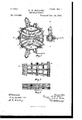
- Figure 1 is a vertical section on line a d of Fig. 3.
- Fig. 2 is a part side elevation and broken section on line c c of Fig. 4.
- Fig. 3 is a section on line BB of Fig. 1.
- Fig. 4 is a section on line E E oi' Fig. 2.
- Fig. 5 is a section on line FF of Fig. 7.
- Fig. 6 is a section on line G G of Fig. 7.
- Fig. 7 is a section on line D D of Fig. 1.
- Fig. 8 is a horizontal section commencing at the 'lining of the left-hand combustionchamber and extending through the central dividing-wall.
- Fig. 9 is avertical section on line H H of Fig. 8.
- Fig. 10 is a plan illustrating one method of running the hotblast connection to the two combustion-chambers.
- Fig. 11 is a like view illustrating ⁇ a second method of running the same connection. Fig.
- ⁇ 12 is a vertical section on line K K of Fig. 13
- Fig. 13 is an irregular.
- the purpose of my invention is a two-pass hot-blast stove with two side combustion-chambers, and by which construction greater uniformity of draft and a vbetter distribution are secured.
- 2 is the metal jacket of the stove.
- 3 is the shell, and 4 the lining of the shell.
- 5 is the dome of the stove, and 6 a false roof separated from said dome by a suitable distance and built independently of the shell of the stove.
- 6a is a block constituting the keystone of the arch of the false roof 6.
- 6b is a self-regulating valve in the dome.
- 11 11 are the gas-inlets, controlled by suit able valves.
- 19 19 are ovalshaped side combustionchambers formed between the lining 4of the shell and arc-shaped walls 20 20.
- 21 21 are the linings of said combustion chambers.
- These combustion-chambers preferably extend from the bottom of the stove to a point a little below where the false roof is sprung. From the ⁇ top level of the chimney-liuc to the false roof extends a central dividing-wall 22.
- the space between said central wall and the ⁇ inner wall of the combustion-chamber and the arc-shaped portions of the shell on both sides of the stove is occupied by arc flues e e, formed between vertical walls n n, as clearly seen in Fig. a.
- the hot-blast and cold-blast valves are closed and IOO the gas and air Valves opened, admitting ⁇ gas and air to each combustion-chamber.
- the gas 'and air burning in said chambers on both sides of the stove ascend to the top of the chambers and the products of combustion are uniformly distributed from each chamber to its respective series of lues e e, descending said iiues to the horizontal flue 23, thence to vertical lues 20 and 28, and from flue 26 through cross-iiues 27 27, and by liue 2S to bottom of stove, and thence through crosslines 29 29 to stack-flue 30 to stack.
- the stove is sufciently heated, the stackvalve is closed and the gas and air inlet valves, While the cold blast is turned on, the cold blast making a reti-averse in precisely opposite direction to that described and escaping to the hot blast.
- thermo-blast stoves In hot-blast stoves the combination of a shell; a vertical wall cutting the stove into substantially two equal divisions; in each division a side combustion-chamber adjacent to the shell; vertical heating-dues in each division between the combustion-cliamber and the vertical dividing wall which prevents communication between the heating-hues of the two divisions; a stack-flue communicating with the heating-fines; a gas-inlet, an airinlet and a hot-blast connection to each combustion-chamber.
Landscapes
- Engineering & Computer Science (AREA)
- Chemical & Material Sciences (AREA)
- Manufacturing & Machinery (AREA)
- Materials Engineering (AREA)
- Metallurgy (AREA)
- Organic Chemistry (AREA)
- Solid-Fuel Combustion (AREA)
Description
(No Model.) 6 Sheets-Sheet 2.
G. W. MGGLURE. HOT BLAST STOVB.
No. 573,902. Patented Dec. 29, 1896.
7N; wams PETERS co., Puurou'mo.. WASHINGTON, n. c.
(No Modem 6 Shets-Sheet 3.4" G. W. MGGLURE'. l
\ HOT'BLAST STOVB. N0. 573,902. Patented Deo. 29, 1896.
ma Ncmms Pneus ca. PHoToLn-No wAsnmaTo. n, c.
`6 Sheets-Sheet 4.
Patented Dec. 2.9,` 1896.
KNO Model.)
No. i573.902.
(No Model.) 6 sheets-sneer. 5.
G. W. MGCLURB. HOT BLAST sToVB.
' No. 573,902. Patented Deo. 29, 1896.
ma Norms 51ans ce.l Fumo-umu.. wAsNmGToN, u. n:A
(No Model.) 6 Sheets-Sheet 6. G. W. MGCLURE.
'HOT BLAST sTovE.
Patented 1390.29. 1896.
TH: uname PETERS CD. PMotaLlTHo., wnsmua'm, D. c.
UNITED STATES 'PATENT OFFICE.
GEORGE lV. MCCLURE, OF PITTSBURG, PENNSYLVANIA.
HOT-BLAST STOVE.
SPECIFICATION forming part of Letters Patent No. 573,902, dated December 29, 1896.
Application filed January 3, 1896. Serial No. 574,200. (No model.)
T all wiz/0m it may concern:
Be it known that I, GEORGE W. MCCLURE, a citizen of the United States,residin g at Pittsburg, in the county of Allegheny and State of Pennsylvania, have invented or discovered new and useful Improvements in Hotlast Stoves, of which the following is a specification.
In the accompanying d rawin gs, which make part of this specication, Figure 1 is a vertical section on line a d of Fig. 3. Fig. 2 is a part side elevation and broken section on line c c of Fig. 4. Fig. 3 is a section on line BB of Fig. 1. Fig. 4 is a section on line E E oi' Fig. 2. Fig. 5 is a section on line FF of Fig. 7. Fig. 6 is a section on line G G of Fig. 7. Fig. 7 is a section on line D D of Fig. 1. Fig. 8 is a horizontal section commencing at the 'lining of the left-hand combustionchamber and extending through the central dividing-wall. Fig. 9 is avertical section on line H H of Fig. 8. Fig. 10 is a plan illustrating one method of running the hotblast connection to the two combustion-chambers. Fig. 11 is a like view illustrating` a second method of running the same connection. Fig.
` 12 is a vertical section on line K K of Fig. 13
and showing straight lines of lues instead of flues run on arcs, and Fig. 13 is an irregular.
horizontal section through the top of a similar stove to Fig. 12.
The purpose of my invention, generally stated, is a two-pass hot-blast stove with two side combustion-chambers, and by which construction greater uniformity of draft and a vbetter distribution are secured.
In the accompanying drawings ,which make part of this specification, 2 is the metal jacket of the stove.
3 is the shell, and 4 the lining of the shell.
5 is the dome of the stove, and 6 a false roof separated from said dome by a suitable distance and built independently of the shell of the stove.
6a is a block constituting the keystone of the arch of the false roof 6.
6b is a self-regulating valve in the dome.
7 is the usual platform, and 8 the stack.
9 is the stack-valve.
10 is the cold-blast inlet.
11 11 are the gas-inlets, controlled by suit able valves.
of the top of the flues, and 17 17 and 18 1S at the two bottom levels of the flues.
The interior construction of the stove,`.as seen in all gures except Figs. 12 and 13, is as follows:
19 19 are ovalshaped side combustionchambers formed between the lining 4of the shell and arc-shaped walls 20 20. 21 21 are the linings of said combustion chambers. These combustion-chambers preferably extend from the bottom of the stove to a point a little below where the false roof is sprung. From the `top level of the chimney-liuc to the false roof extends a central dividing-wall 22. The space between said central wall and the `inner wall of the combustion-chamber and the arc-shaped portions of the shell on both sides of the stove is occupied by arc flues e e, formed between vertical walls n n, as clearly seen in Fig. a.
The manner in which the masonry is built i up for the flues is shown in Figs. 7 and S.
extending to the level of the top of the chimney-Iiue and connecting by cross-flues 27 27 through said arches with a second vertical flue on each side 2S 28, extending to the bottom of the stove. By cross-nues 29 29 ues 2S 28 connect with stack-flue 30.
In the modiication shown in Figs. 12 and 13 the checker-work of the flues e' e is formed between vertical walls n n', running straight across the stove instead of on arcs of circles.
There are no other significant changes between the two constructions.
In operation when the stove is on gas the hot-blast and cold-blast valves are closed and IOO the gas and air Valves opened, admitting` gas and air to each combustion-chamber. The gas 'and air burning in said chambers on both sides of the stove ascend to the top of the chambers and the products of combustion are uniformly distributed from each chamber to its respective series of lues e e, descending said iiues to the horizontal flue 23, thence to vertical lues 20 and 28, and from flue 26 through cross-iiues 27 27, and by liue 2S to bottom of stove, and thence through crosslines 29 29 to stack-flue 30 to stack. Then the stove is sufciently heated, the stackvalve is closed and the gas and air inlet valves, While the cold blast is turned on, the cold blast making a reti-averse in precisely opposite direction to that described and escaping to the hot blast.
I do not claim in this application the ieature of the false roof, nor its independency of the shell of the stove, nor the automatic valve which controls the entrance of air into the space between the roof and the inner dome, nor the feature of building the combustionchambers, linings, and Ilues independent of each other, as such constitutes the subjectmatter, nter alia, of a separate application filed by me October 17, 1895, Serial No. 565,933; but I do claim, broadly, the general arrangement of the combustion-chambers and iiues of this double stove in one shell and the connection therewith of the gas, air, and hotblast connection.
Having described my invention, I claiml. In hot-blast stoves the combination of a shell; a vertical wall cutting the stove into substantially two equal divisions; in each division a side combustion-chamber adjacent to the shell; vertical heating-fines in each division between the combustion-chaniber and the vertical dividing wall which prevents communication between the heating-fines of the two divisions and a stack-flue communicating with the heating-nues.
2. In hot-blast stoves, the combination of a shell; a wall dividing the stove into two parts; an oval side combustion-chamber and vertical heating-fines running on arcs in each division, and a stack-flue communicating with the heating-hues.
3. In hot-blast stoves the combination of a shell; a vertical wall cutting the stove into substantially two equal divisions; in each division a side combustion-chamber adjacent to the shell; vertical heating-dues in each division between the combustion-cliamber and the vertical dividing wall which prevents communication between the heating-hues of the two divisions; a stack-flue communicating with the heating-fines; a gas-inlet, an airinlet and a hot-blast connection to each combustion-chamber.
4t. In hot-blast stoves, the combination of a shell; a wall dividing the stove into two parts; a side com bustion-chamber and vertical heating-fines in each division; a horizontal flue at the base of each set of said vertical heating-dues; an inner and outer vertical iiue beneath each of said horizontal lues; connections between said inner and outer vertical ilues; a stack-flue and connections between said stack-flue and said outer vertical fiue.
In testimony whereof I have hereunto set my hand this 30th da)7 of December, A. D. l 895.
GEORGE IV. MCGLURE.
Witnesses LUCY D. IAMs, WM. L. PIERCE.
Publications (1)
| Publication Number | Publication Date |
|---|---|
| US573902A true US573902A (en) | 1896-12-29 |
Family
ID=2642597
Family Applications (1)
| Application Number | Title | Priority Date | Filing Date |
|---|---|---|---|
| US573902D Expired - Lifetime US573902A (en) | Hot-blast stove |
Country Status (1)
| Country | Link |
|---|---|
| US (1) | US573902A (en) |
-
0
- US US573902D patent/US573902A/en not_active Expired - Lifetime
Similar Documents
| Publication | Publication Date | Title |
|---|---|---|
| US573900A (en) | Hot-blast stove | |
| US711089A (en) | Hot-blast stove. | |
| US1141108A (en) | Hot-blast stove. | |
| US574041A (en) | Mcolure | |
| US573901A (en) | Hot-blast stove | |
| US88083A (en) | Improvement in blast, smelting, and cupola furnaces | |
| US370957A (en) | lipsey | |
| US415226A (en) | Hot-blast stove | |
| US379707A (en) | Regenerative hot-blast stove | |
| US524915A (en) | Regenerative furnace | |
| US117246A (en) | Improvements in working blast-furnaces | |
| US103651A (en) | Improvement in hot-blast ovens | |
| US1079764A (en) | Air-blast heater. | |
| US240845A (en) | Regenerative metallurgical furnace | |
| US429725A (en) | Hot-blast stove | |
| US535292A (en) | Garbage-furnace | |
| US46984A (en) | Improvement in roasting and desulphurizing ores | |
| US263985A (en) | spbinger | |
| US491066A (en) | archer | |
| US413927A (en) | blanceard | |
| US839160A (en) | Zinc-smelting furnace. | |
| US360973A (en) | Hot-blast stove | |
| US210369A (en) | Improvement in metallurgic furnaces | |
| US198820A (en) | Improvement in hot-blast ovens | |
| US357030A (en) | radcliffe |