US572611A - Half to j - Google Patents
Half to j Download PDFInfo
- Publication number
- US572611A US572611A US572611DA US572611A US 572611 A US572611 A US 572611A US 572611D A US572611D A US 572611DA US 572611 A US572611 A US 572611A
- Authority
- US
- United States
- Prior art keywords
- nozzle
- fan
- suction
- shaft
- cotton
- Prior art date
- Legal status (The legal status is an assumption and is not a legal conclusion. Google has not performed a legal analysis and makes no representation as to the accuracy of the status listed.)
- Expired - Lifetime
Links
- 239000004020 conductor Substances 0.000 description 15
- 229920000742 Cotton Polymers 0.000 description 14
- 238000010276 construction Methods 0.000 description 7
- 101100172874 Caenorhabditis elegans sec-3 gene Proteins 0.000 description 1
- 101100005297 Mus musculus Cat gene Proteins 0.000 description 1
- 230000004941 influx Effects 0.000 description 1
- 239000000463 material Substances 0.000 description 1
Images


Classifications
-
- A—HUMAN NECESSITIES
- A01—AGRICULTURE; FORESTRY; ANIMAL HUSBANDRY; HUNTING; TRAPPING; FISHING
- A01D—HARVESTING; MOWING
- A01D46/00—Picking of fruits, vegetables, hops, or the like; Devices for shaking trees or shrubs
- A01D46/08—Picking of fruits, vegetables, hops, or the like; Devices for shaking trees or shrubs of cotton
- A01D46/10—Picking of fruits, vegetables, hops, or the like; Devices for shaking trees or shrubs of cotton pneumatically
Definitions
- My invention relates to cotton-picking apparatus, and has for its object to provide a simple and improved device for picking cotton from the boll and conveying it to a suitable receptacle arranged upon a truck, the apparatus being so constructed as to reduce to a minimum the weight of the nozzle which is held by the operator, the means for operating the movable parts of the nozzle being arranged contiguous to the suction-fan and hence supported by the truck, and, furthermore, to reduce to a minimum the resistance ofiered to the cotton in passing through the nozzle and the flexible conductor by which the nozzle is connected with the suction-fan.
- Figure 1 is a side view of an apparatus constructed in accordance with my invention, the flexible conductor being shown partly broken away.
- Fig. 2 is a plan View, partly in section, of the suction-fan and means for communicating motion to the flexible shaft.
- Fig. 3 is a detail longitudinal sec- 3 5 tion of the nozzle, showing the inner or rotary member in elevation.
- Fig. l is a similar View of the nozzle, showing the rotary member in section.
- Fig. 5 is a transverse sectional view of the nozzle on the line 5 5 of Fig. 3 to show the means for communicating motion from the flexible shaft to the rotary member.
- Fig. 1 is a side view of an apparatus constructed in accordance with my invention, the flexible conductor being shown partly broken away.
- Fig. 2 is a plan View, partly in section, of the suction-fan and means for communicating motion to the flexible shaft.
- Fig. 3 is a detail longitudinal sec- 3 5 tion of the nozzle, showing the inner or rotary
- Fig. 6 is a longitudinal section of a slightly-modified form of nozzle in which centrifugal instead of centripetal force is exerted upon the cotton in its passage therethrough.
- Fig. 7 is a plan view, partly in section, of the suction-fan and means for communicating motion to the flexible shaft as Serial No. 560,775. (No modem used in connection with the modified form of nozzle.
- FIG. 1 designates a truck upon which. may be mounted a motor of any suitable construction for imparting rotary motion to the shaft 2 of a suction-fan 3, said fan being also carried by the truck.
- the suction-fan is provided with the usual side inlet 4, with which communicates the flexible conductor 5, terminating at its free end in a nozzle 6.
- the nozzle comprises an outer cylindrical casing 7 and an inner rotary member 7 also of cylindrical construction, which is supported by antifriction-rollers 8, mounted inv opposite extensions 9 of the casin g. Said antifriction-rollers extend slightly beyond the inner surface of the casing and fit in annular guide-grooves 10, formed in the rotary member.
- the rotary member is provided with detaching or separating wings 11 and 12, located, respectively, at the front and rear ends of said part, said wings being spiral in construction and being designed to act upon the cotton substantially in the manner of an anger in its passage therethrough, said movement of the cotton through the .nozzle being assisted, however, by the influx of air produced by the suction-fan at the other end of the conductor.
- the front end of the rotary member is flanged, as shown at 13, to overlap the front end of the casing and prevent cotton from passing between the same.
- Motion is com munioated to the rotary member of the nozzle by means of a gear 14, arranged at the rear end of said member, and a pinion 15, meshing with said gear and receiving motion from the flexible shaft 16, ar- 0 ranged in a flexible tube 17, which extends parallel with the flexible conductor.
- the flexible conductor is constructed mainly of coiled wire, as shown at 18, and is provided with an inner lining 19 and an outer sheath 5 or covering 20, of sheet rubber or similar material, impervious to air and adapted to form a smooth surface.
- the flexible tube in which the shaft is located is also constructed of coiled wire, as shown at 21, and is provided with a flexible covering 22, of rubber shaft, and also provided with a beve1-gear32, meshing witha pinion 38 on the end of the flexible shaft, the contiguous end of the flexible shaft being mounted in a bearing formed in a bracket 34, attached to the side of the suction-fan casing.
- the extendedspindle of the suction-fan is provided with a belt-put ley 35, by which the :fan may receive motion through .a belt '36 from the motor.
- the nozzle comprises an outer member or casing 37, of cylindrical construction, connected with the flexible conductor and an inner rotary member 38, provided with wings 39; but instead of said rotary member, consisting of a cylinder and interior wings, as in the form illustrated inFigs. 1 to 5, it consists of a central shaft 40., provided with exterior or centrifugal wings 41, said Wings being loca-ted at the rear end, of the shaft or spindle.
- the means for communicating motion to the rotary member of the nozzle are located mainly upon or contiguous to the suction fan, whereby the nozzle is relieved of the weight thereof, and the means for transmitting motion throughout the length of the flexible conductor are such as to permit the free;
- a nozzle having an exteriorcasingand an interior rotary winged member for separating the cotton from the bolls, a flexible conductor connecting thecasing of the nozzle with the casing of the suction-fan, a flexible shaft'operatively connected with the rotary "member of the nozzle, means for communicating motion to the shaft, and a flexible tube in-closing the shaft and consistin g of a coiled-wire body having a flexible sheath or covering, substantially as specified.
- a device of the class described the combination with a suction-fan and means for ope-rating the same, of a nozzle having an exterior cylindrical casing, and an interior cylindrical rotary member provided with in terior spirally-disposed wings located at its front and rear end-s, autifrictionu olls mounted upon the casing and projecting at their inner edges into .guide'g-rooves formed in the exterior surface of the rotary'member, a flexible conductor connecting the casin g of the nozzle with the casin g of the su ction-fa-n,.and means for communicating motion to the rotary mem ber of the nozzle, substantially as specified.
- gearing interposed between the flexible shaft and the shaft or spindle of the fa-nysaid gearing consisting of shafts and intermeshing pinions for conveying motion around the casmg of the fan to that side contiguous to the point-of attachment of the flexible conductor, substantially as specified.
Landscapes
- Life Sciences & Earth Sciences (AREA)
- Environmental Sciences (AREA)
- Preliminary Treatment Of Fibers (AREA)
Description
(No Model.) 3 Sheets-Sheet 1.
G. O. NEIGHBOURS. COTTON PIGKBR.
No. 572,611. Patented 'Dec. 8, 1896.
(Nb Model.) 3 Sheets-Sheet 2.
' 0. 0. NEIGHBOURS.
COTTON PIGKER Patented Dec. 8
(No Modem I 3 Sheets-Sheet 3.
O. 0. NEIGHBOURS. COTTON PICKBR.
No. 572,611. Patented Dec. 8, 1896.
UNITED STATES PATENT OFFICE.
CHARLES NEIGHBOURS, OF FORT SMITH, ARKANSAS, ASSIGNOR OF ONE- HALF TO J. WVARREN REED, OF SAME PLACE.
PICKER.
SPECIFICATION formingwe of Letters Patent No. 572,611, dated December 8, 1896.
Application filed August 28 1895.
v To all whom it may concern:
Be it known that I, CHARLES C. NEIGH- BOURS, a citizen of the United States, residing at Fort Smith, in the county of Sebas tian and State of Arkansas, have invented a new and useful Cotton-Picker, of which the following is a specification.
My invention relates to cotton-picking apparatus, and has for its object to provide a simple and improved device for picking cotton from the boll and conveying it to a suitable receptacle arranged upon a truck, the apparatus being so constructed as to reduce to a minimum the weight of the nozzle which is held by the operator, the means for operating the movable parts of the nozzle being arranged contiguous to the suction-fan and hence supported by the truck, and, furthermore, to reduce to a minimum the resistance ofiered to the cotton in passing through the nozzle and the flexible conductor by which the nozzle is connected with the suction-fan.
Further objects and advantages of this invention will appear in the following descrip- 2 5 tion, and the novel features thereof will be particularly pointed out in the appended claims.
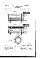
In the drawings, Figure 1 is a side view of an apparatus constructed in accordance with my invention, the flexible conductor being shown partly broken away. Fig. 2 is a plan View, partly in section, of the suction-fan and means for communicating motion to the flexible shaft. Fig. 3 is a detail longitudinal sec- 3 5 tion of the nozzle, showing the inner or rotary member in elevation. Fig. l is a similar View of the nozzle, showing the rotary member in section. Fig. 5 is a transverse sectional view of the nozzle on the line 5 5 of Fig. 3 to show the means for communicating motion from the flexible shaft to the rotary member. Fig. 6 is a longitudinal section of a slightly-modified form of nozzle in which centrifugal instead of centripetal force is exerted upon the cotton in its passage therethrough. Fig. 7 is a plan view, partly in section, of the suction-fan and means for communicating motion to the flexible shaft as Serial No. 560,775. (No modem used in connection with the modified form of nozzle.
' Similar numerals of reference indicate corresponding parts in all the figures of the drawings.
1 designates a truck upon which. may be mounted a motor of any suitable construction for imparting rotary motion to the shaft 2 of a suction-fan 3, said fan being also carried by the truck. The suction-fan is provided with the usual side inlet 4, with which communicates the flexible conductor 5, terminating at its free end in a nozzle 6.
In the construction illustrated in Figs. 1, 3, 4, and 5 the nozzle comprises an outer cylindrical casing 7 and an inner rotary member 7 also of cylindrical construction, which is supported by antifriction-rollers 8, mounted inv opposite extensions 9 of the casin g. Said antifriction-rollers extend slightly beyond the inner surface of the casing and fit in annular guide-grooves 10, formed in the rotary member. The rotary member is provided with detaching or separating wings 11 and 12, located, respectively, at the front and rear ends of said part, said wings being spiral in construction and being designed to act upon the cotton substantially in the manner of an anger in its passage therethrough, said movement of the cotton through the .nozzle being assisted, however, by the influx of air produced by the suction-fan at the other end of the conductor. The front end of the rotary member is flanged, as shown at 13, to overlap the front end of the casing and prevent cotton from passing between the same.
Motion is com munioated to the rotary member of the nozzle by means of a gear 14, arranged at the rear end of said member, and a pinion 15, meshing with said gear and receiving motion from the flexible shaft 16, ar- 0 ranged in a flexible tube 17, which extends parallel with the flexible conductor. The flexible conductor is constructed mainly of coiled wire, as shown at 18, and is provided with an inner lining 19 and an outer sheath 5 or covering 20, of sheet rubber or similar material, impervious to air and adapted to form a smooth surface. The flexible tube in which the shaft is located is also constructed of coiled wire, as shown at 21, and is provided with a flexible covering 22, of rubber shaft, and also provided with a beve1-gear32, meshing witha pinion 38 on the end of the flexible shaft, the contiguous end of the flexible shaft being mounted in a bearing formed in a bracket 34, attached to the side of the suction-fan casing. The extendedspindle of the suction-fan is provided with a belt-put ley 35, by which the :fan may receive motion through .a belt '36 from the motor.
In the construction illustrated in Figs. 6 and '7 the nozzle comprises an outer member or casing 37, of cylindrical construction, connected with the flexible conductor and an inner rotary member 38, provided with wings 39; but instead of said rotary member, consisting of a cylinder and interior wings, as in the form illustrated inFigs. 1 to 5, it consists of a central shaft 40., provided with exterior or centrifugal wings 41, said Wings being loca-ted at the rear end, of the shaft or spindle.
At the front end of the shaft or spindle, the extremity thereof being tapered or pointed, are located rearwardly-projecting pins 42,
which are designed to engage and separate the cotton from the bollsand then release the same under theaction of the suction-fan and allow it to pass rearwardly through the conductor. In this modified form of theapparatus instead of arranging the flexible shaft exteriorly I extend it through the flexible conductor, thefront end thereof being-connected to an eyeii at the rear end of the rotary member of the nozzle and the rear end thereof being connected by gearing, substantially as above described, with the shaft .or spindle of the suction-fan, a boxing 45 being arranged around the contiguous portions of the gearing to prevent contact of the cotton therewith.
From the above description it will be seen that the means for communicating motion to the rotary member of the nozzle are located mainly upon or contiguous to the suction fan, whereby the nozzle is relieved of the weight thereof, and the means for transmitting motion throughout the length of the flexible conductor are such as to permit the free;
movement of the nozzle and avoid catching the cotton in its passage through the concluctor.
Various changes in the form, proportion, and the minor details of construction maybe resorted without departing from the spirit or sacrificing any of the advantages of this invention.
Having described my invention, what I claim is- 1. In adevice of the class described, the combination with a suction-fan and means for operating the same, of a nozzle having a movable part adapted to engage and separate the cotton from the bolls, a flexible conductor connecting the nozzle with the suction-fan, a flexible shaft operatively connected with the movable member of the nozzle, and means for communicating motion to the shaft, substantially as specified.
2.. In :a device of the class described, the
combination with a suction-fan and means -foroperating the same, of a nozzle having an exteriorcasingand an interior rotary winged member for separating the cotton from the bolls, a flexible conductor connecting thecasing of the nozzle with the casing of the suction-fan,a flexible shaft'operatively connected with the rotary "member of the nozzle, means for communicating motion to the shaft, and a flexible tube in-closing the shaft and consistin g of a coiled-wire body having a flexible sheath or covering, substantially as specified. In a device of the class described, the combination with a suction-fan and means for ope-rating the same, of a nozzle having an exterior cylindrical casing, and an interior cylindrical rotary member provided with in terior spirally-disposed wings located at its front and rear end-s, autifrictionu olls mounted upon the casing and projecting at their inner edges into .guide'g-rooves formed in the exterior surface of the rotary'member, a flexible conductor connecting the casin g of the nozzle with the casin g of the su ction-fa-n,.and means for communicating motion to the rotary mem ber of the nozzle, substantially as specified.
at. In a'd-evice of the class described, the
combination with a suction fan and means at one-end contiguous to the fan-casing, and
gearing interposed between the flexible shaft and the shaft or spindle of the fa-nysaid gearing consisting of shafts and intermeshing pinions for conveying motion around the casmg of the fan to that side contiguous to the point-of attachment of the flexible conductor, substantially as specified.
'5. In a device of the class described, the
combination with a suction-fan and means fo-roperating the same, :of a nozzle having an exterior cylindrical casing and an interior cylindrical rotary member provided with in- In testimony that I claim the foregoing as terior spirally-disposed Wing's located at its my own I have hereto aifixed my signature in 10 front and rear ends, a flexible conductor conin the presence of tWo Witnesses. necting the casing of the nozzle with the cas- 1 5 ing of the fan, and means including afiexible CHARLES NEIGHBOURS' shaft for communicating motion to the rotary WVitnesses: member of the nozzle, substantially as speci- W. H. BOWERS, fled. JOHN KNOWLES.
Publications (1)
| Publication Number | Publication Date |
|---|---|
| US572611A true US572611A (en) | 1896-12-08 |
Family
ID=2641308
Family Applications (1)
| Application Number | Title | Priority Date | Filing Date |
|---|---|---|---|
| US572611D Expired - Lifetime US572611A (en) | Half to j |
Country Status (1)
| Country | Link |
|---|---|
| US (1) | US572611A (en) |
Cited By (1)
| Publication number | Priority date | Publication date | Assignee | Title |
|---|---|---|---|---|
| US2499693A (en) * | 1945-03-24 | 1950-03-07 | Thomas D Stanton | Pneumatic cotton picker nozzle |
-
0
- US US572611D patent/US572611A/en not_active Expired - Lifetime
Cited By (1)
| Publication number | Priority date | Publication date | Assignee | Title |
|---|---|---|---|---|
| US2499693A (en) * | 1945-03-24 | 1950-03-07 | Thomas D Stanton | Pneumatic cotton picker nozzle |
Similar Documents
| Publication | Publication Date | Title |
|---|---|---|
| US767058A (en) | Cotton-picker. | |
| US1032115A (en) | Cotton-picker. | |
| US202042A (en) | Improvement in fruit-pickers | |
| US1096325A (en) | Cotton-picking device. | |
| US246818A (en) | wiley | |
| US923649A (en) | Cotton-picker. | |
| US498133A (en) | Pneumatic cotton-picker | |
| US1067802A (en) | Vacuum-head for cotton-picking machines. | |
| US752790A (en) | Pneumatic boll-weevil machine | |
| US1498612A (en) | Pneumatic cotton-picking machine | |
| US901619A (en) | Cotton-picker. | |
| US1014880A (en) | Cotton-harvesting machine. | |
| US608689A (en) | Cotton-harvester | |
| US545117A (en) | young | |
| US1083079A (en) | Cotton-picker. | |
| US848967A (en) | Cotton-picker. | |
| US859204A (en) | Picker-nozzle for pneumatic cotton-picking machines. | |
| US783685A (en) | Cotton-picker. | |
| US1228238A (en) | Cotton-picking machine. | |
| US1052361A (en) | Cotton-gathering apparatus. | |
| US1844785A (en) | Cotton picking machine | |
| US1277901A (en) | Cotton-picking machine. | |
| US1355786A (en) | Vacuum-nozzle for cotton-picking machines | |
| US812865A (en) | Cotton-picking machine. | |
| US948846A (en) | Cotton-harvester. |