US5707167A - Extendable rod - Google Patents
Extendable rod Download PDFInfo
- Publication number
- US5707167A US5707167A US08/657,185 US65718596A US5707167A US 5707167 A US5707167 A US 5707167A US 65718596 A US65718596 A US 65718596A US 5707167 A US5707167 A US 5707167A
- Authority
- US
- United States
- Prior art keywords
- bracelet
- lever
- rod
- depression
- end portion
- Prior art date
- Legal status (The legal status is an assumption and is not a legal conclusion. Google has not performed a legal analysis and makes no representation as to the accuracy of the status listed.)
- Expired - Fee Related
Links
- 230000000694 effects Effects 0.000 description 2
- 229910001369 Brass Inorganic materials 0.000 description 1
- 229910000906 Bronze Inorganic materials 0.000 description 1
- 239000004677 Nylon Substances 0.000 description 1
- 239000004809 Teflon Substances 0.000 description 1
- 229920006362 Teflon® Polymers 0.000 description 1
- 239000010951 brass Substances 0.000 description 1
- 239000010974 bronze Substances 0.000 description 1
- KUNSUQLRTQLHQQ-UHFFFAOYSA-N copper tin Chemical compound [Cu].[Sn] KUNSUQLRTQLHQQ-UHFFFAOYSA-N 0.000 description 1
- 230000008878 coupling Effects 0.000 description 1
- 238000010168 coupling process Methods 0.000 description 1
- 238000005859 coupling reaction Methods 0.000 description 1
- 238000003754 machining Methods 0.000 description 1
- 238000004519 manufacturing process Methods 0.000 description 1
- 239000000463 material Substances 0.000 description 1
- 239000007769 metal material Substances 0.000 description 1
- 229920001778 nylon Polymers 0.000 description 1
- 239000004033 plastic Substances 0.000 description 1
- 229920003023 plastic Polymers 0.000 description 1
- 239000000126 substance Substances 0.000 description 1
Images


Classifications
-
- F—MECHANICAL ENGINEERING; LIGHTING; HEATING; WEAPONS; BLASTING
- F16—ENGINEERING ELEMENTS AND UNITS; GENERAL MEASURES FOR PRODUCING AND MAINTAINING EFFECTIVE FUNCTIONING OF MACHINES OR INSTALLATIONS; THERMAL INSULATION IN GENERAL
- F16M—FRAMES, CASINGS OR BEDS OF ENGINES, MACHINES OR APPARATUS, NOT SPECIFIC TO ENGINES, MACHINES OR APPARATUS PROVIDED FOR ELSEWHERE; STANDS; SUPPORTS
- F16M11/00—Stands or trestles as supports for apparatus or articles placed thereon ; Stands for scientific apparatus such as gravitational force meters
- F16M11/20—Undercarriages with or without wheels
- F16M11/24—Undercarriages with or without wheels changeable in height or length of legs, also for transport only, e.g. by means of tubes screwed into each other
- F16M11/26—Undercarriages with or without wheels changeable in height or length of legs, also for transport only, e.g. by means of tubes screwed into each other by telescoping, with or without folding
- F16M11/28—Undercarriages for supports with one single telescoping pillar
-
- F—MECHANICAL ENGINEERING; LIGHTING; HEATING; WEAPONS; BLASTING
- F16—ENGINEERING ELEMENTS AND UNITS; GENERAL MEASURES FOR PRODUCING AND MAINTAINING EFFECTIVE FUNCTIONING OF MACHINES OR INSTALLATIONS; THERMAL INSULATION IN GENERAL
- F16M—FRAMES, CASINGS OR BEDS OF ENGINES, MACHINES OR APPARATUS, NOT SPECIFIC TO ENGINES, MACHINES OR APPARATUS PROVIDED FOR ELSEWHERE; STANDS; SUPPORTS
- F16M2200/00—Details of stands or supports
- F16M2200/02—Locking means
- F16M2200/025—Locking means for translational movement
- F16M2200/027—Locking means for translational movement by friction
-
- Y—GENERAL TAGGING OF NEW TECHNOLOGICAL DEVELOPMENTS; GENERAL TAGGING OF CROSS-SECTIONAL TECHNOLOGIES SPANNING OVER SEVERAL SECTIONS OF THE IPC; TECHNICAL SUBJECTS COVERED BY FORMER USPC CROSS-REFERENCE ART COLLECTIONS [XRACs] AND DIGESTS
- Y10—TECHNICAL SUBJECTS COVERED BY FORMER USPC
- Y10T—TECHNICAL SUBJECTS COVERED BY FORMER US CLASSIFICATION
- Y10T403/00—Joints and connections
- Y10T403/32—Articulated members
- Y10T403/32254—Lockable at fixed position
- Y10T403/32467—Telescoping members
-
- Y—GENERAL TAGGING OF NEW TECHNOLOGICAL DEVELOPMENTS; GENERAL TAGGING OF CROSS-SECTIONAL TECHNOLOGIES SPANNING OVER SEVERAL SECTIONS OF THE IPC; TECHNICAL SUBJECTS COVERED BY FORMER USPC CROSS-REFERENCE ART COLLECTIONS [XRACs] AND DIGESTS
- Y10—TECHNICAL SUBJECTS COVERED BY FORMER USPC
- Y10T—TECHNICAL SUBJECTS COVERED BY FORMER US CLASSIFICATION
- Y10T403/00—Joints and connections
- Y10T403/70—Interfitted members
- Y10T403/7062—Clamped members
- Y10T403/7064—Clamped members by wedge or cam
- Y10T403/7066—Clamped members by wedge or cam having actuator
- Y10T403/7071—Lever actuator
-
- Y—GENERAL TAGGING OF NEW TECHNOLOGICAL DEVELOPMENTS; GENERAL TAGGING OF CROSS-SECTIONAL TECHNOLOGIES SPANNING OVER SEVERAL SECTIONS OF THE IPC; TECHNICAL SUBJECTS COVERED BY FORMER USPC CROSS-REFERENCE ART COLLECTIONS [XRACs] AND DIGESTS
- Y10—TECHNICAL SUBJECTS COVERED BY FORMER USPC
- Y10T—TECHNICAL SUBJECTS COVERED BY FORMER US CLASSIFICATION
- Y10T403/00—Joints and connections
- Y10T403/70—Interfitted members
- Y10T403/7075—Interfitted members including discrete retainer
- Y10T403/7077—Interfitted members including discrete retainer for telescoping members
Definitions
- the present invention relates to an extendable rod including at least two rod-shaped elements which can slide telescopically into one another, and means for extending the rod and locking the rod-shaped elements in the extended position, these means comprising a bracelet which is mounted on one of the rod-shaped elements and which can be tightened thereon by means of a bolt, a lever pivoted on the bracelet by means of the bolt, and means providing a front cam between the lever and the bracelet for permitting sliding of the bracelet on the corresponding rod-shaped element in a first operative position of the lever and for tightening the bracelet on the corresponding rod-shaped element in a second operative position of the lever.
- Rods having the above-mentioned characteristics are known, for example, from the current production of the Applicant and are customarily used as elements of frame structures, modular structures and sectional structures, or as a support for photo-cinematographic equipment.
- the rods In order to lock the bracelet on the corresponding rod-shaped element, the rods generally have a pair of front cams, which are respectively rotationally fast with the bracelet and with the lever in such a manner that they are rotated with respect to one another as a result of the rotation of the lever.
- the lever is pivoted on the bracelet by means of the bolt and owing to the shape of the profile of the cam, the rotation of the lever in one sense enables the bracelet to be tightened on the rod-shaped element, while rotation in the opposite sense enables this tightening to be loosened in order to permit the sliding of the bracelet on the corresponding rod-shaped element.
- cams are provided on the lever and on the bracelet by relatively complicated machining.
- the technical problem forming the basis of the present invention is to provide an extendable rod which is designed structurally and functionally to avoid all the disadvantages described with reference to the mentioned prior art.
- an extendable rod of the type indicated in the introduction which is characterised in that the means providing a front cam comprise at least a first depression in the bracelet, at least one end portion of the lever where the lever is pivoted on the bracelet, the end portion being received in the depression when the lever is in the first operative position, and at least one surface of the bracelet which is raised with respect to the depression so that the bracelet is tightened on the corresponding rod-shaped element when the end portion of the lever is engaged on the surface in the second operative position of the lever.
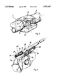
- FIG. 1 is a front elevation of an extendable rod according to the invention
- FIG. 2 is a perspective view of a detail of the rod of FIG. 1 in a first operative position
- FIG. 3 is a partly sectional perspective view of the detail of FIG. 2 in a second operative position
- FIGS. 4 and 5 are perspective partial views of the detail of FIGS. 2 and 3.
- FIG. 1 an extendable rod produced in accordance with the present invention is generally indicated 1.
- the rod 1 comprises two tubular rod-shaped elements 2, 3 which can slide telescopically into one another.
- a respective foot 4, 5 having a widened base is arranged on the free end of each rod-shaped element 2, 3.
- the rod 1 also comprises a first and a second bracelet, indicated 6 and 7, which are mounted respectively on the first and second rod-shaped elements 2, 3.
- the two bracelets 6, 7 have the general shape of a cylindrical sleeve which is open along one of its generatrices, in the area of which the bracelets 6, 7 have respective wings 6a,b and 7a,b.
- the first bracelet 6 is locked on the corresponding rod-shaped element 2 by means of a screw 10 tightened between the wings 6a,b.
- the second bracelet 7 can be releasably locked on the corresponding rod-shaped element 3 by means of a bolt 11 extending between the wings 7a,b.
- a lever, indicated 12, is pivoted at one 12a of its end portions on the bracelet 7 by means of the bolt 11.
- the lever 12 belongs to a toggle-type expander lever mechanism generally indicated 25 which includes a link 26 of which the opposing ends 28, 29 are respectively hinged to the bracelet 6 by means of the screw 10 and are articulated to the lever 12 by means of a pivot pin 32 which passes through a slot 33 in the link 26 and is secured to the lever at a predetermined distance from the bolt 11.
- the bracelet 7 has a first depression, indicated by the reference numeral 15, which extends, starting from the free end of the wing 7b, along a directrix which is at an angle to the longitudinal directrix of the rod.
- the depression 15 is formed in a surface 16 of the bracelet 7 which is raised with respect to that depression.
- a second depression 17 is formed in the surface 16; this depression 17 extends along the longitudinal directrix of the rod 1 and intersects the first depression 15 in correspondence with the axis of the bolt 11.
- the depression 15 is deeper than the depression 17 with respect to the lip of the surface 16 of the bracelet 7 and can receive the end portion 12a of the lever 12 when the latter is in a first operative position (FIG. 2) in which the bracelet 7 can slide freely on the rod-shaped element 3.
- two rollers 20, 21 are mounted idly on the end portion 12a of the lever 12.
- the rollers 20, 21 are arranged axially, respectively between a shoulder 24 of the lever 12 and the end, pivoted on the lever, of the bolt 11, and between the end of the bolt 11 and a stop ring 23 mounted on the free end of the portion 12a.
- the rollers 20 and 21 are produced from plastics material (for example nylon or Teflon) or from metal material (for example bronze or brass) and are used to reduce the contact-induced surface friction between the end portion 12a and the surface 16 of the bracelet 7 on which said portion is engaged.
- the lever 12 is represented in a first operative position. In that position, the rollers 20, 21 of the portion 12a are partially accommodated in the depression 15.
- the depth of the depression 15 with respect to the surface 16 is such that the bracelet 7 can slide freely relative to the rod-shaped element 3 so that it permits the desired positioning of the rod 1, as a function, for example, of the clear span between the walls against which the ends of the rod are pressed.
- the lever 12 With that position preset, the lever 12 is rotated about the axis of the bolt 11 towards the second operative position of FIG. 3 in which it is locked in position parallel to the rod 1.
- the surface 16 is engaged by the rollers 20, 21 of the end portion 12a. Since the surface 16 is raised with respect to the depression 15, the wings 7a,b are urged, by means of the bolt 11, to move towards one another in such a manner that the bracelet 7 is tightened on the rod-shaped element 3.
- the rollers 20, 21 are partially sunk in the depression 17, in such a manner as to prevent the inadvertent rotation of the lever 12.
- the depression 17 has a smaller depth than has the depression 15 and is selected in such a manner that the bracelet 7 is nevertheless firmly tightened, by means of the bolt 11, on the rod-shaped element 3 when the lever 12 is in the second operative position.
Landscapes
- Engineering & Computer Science (AREA)
- General Engineering & Computer Science (AREA)
- Mechanical Engineering (AREA)
- Clamps And Clips (AREA)
- Adornments (AREA)
- Walking Sticks, Umbrellas, And Fans (AREA)
Abstract
Description
Claims (7)
Applications Claiming Priority (2)
| Application Number | Priority Date | Filing Date | Title |
|---|---|---|---|
| ITPD95A0138 | 1995-07-05 | ||
| IT95PD000138A IT1281960B1 (en) | 1995-07-05 | 1995-07-05 | EXTENDABLE AUCTION |
Publications (1)
| Publication Number | Publication Date |
|---|---|
| US5707167A true US5707167A (en) | 1998-01-13 |
Family
ID=11391095
Family Applications (1)
| Application Number | Title | Priority Date | Filing Date |
|---|---|---|---|
| US08/657,185 Expired - Fee Related US5707167A (en) | 1995-07-05 | 1996-06-03 | Extendable rod |
Country Status (4)
| Country | Link |
|---|---|
| US (1) | US5707167A (en) |
| EP (1) | EP0752554B1 (en) |
| DE (1) | DE69606926T2 (en) |
| IT (1) | IT1281960B1 (en) |
Cited By (9)
| Publication number | Priority date | Publication date | Assignee | Title |
|---|---|---|---|---|
| US6083108A (en) * | 1998-05-07 | 2000-07-04 | General Electric Co. | Collapsible and relatively rotatable drive shaft |
| US6142699A (en) * | 1998-04-21 | 2000-11-07 | Asia Link Co., Ltd. | Telescopic rod |
| US6167777B1 (en) * | 1998-12-14 | 2001-01-02 | Chrysler Corporation | Tiltable steering column lock mechanism |
| US6267528B1 (en) * | 1998-07-13 | 2001-07-31 | Nsk Ltd. | Coupling structure of variable length shaft |
| US20040056527A1 (en) * | 2000-05-15 | 2004-03-25 | Lance Mark Andrew | Clamp for a lumbar support |
| US20050185983A1 (en) * | 2004-02-19 | 2005-08-25 | Samsung Electronics Co., Ltd. | Electrophotographic image forming apparatus |
| US20100282520A1 (en) * | 2009-05-05 | 2010-11-11 | Lucas Bruce C | System and Methods for Monitoring Multiple Storage Units |
| US7845602B1 (en) | 2006-02-09 | 2010-12-07 | Primos, Inc. | Telescoping support stand apparatus |
| US8146876B1 (en) | 2006-02-09 | 2012-04-03 | Primos, Inc. | Telescoping support stand apparatus |
Families Citing this family (1)
| Publication number | Priority date | Publication date | Assignee | Title |
|---|---|---|---|---|
| EP1136053B1 (en) * | 2000-03-20 | 2004-12-01 | Yuji Sumida | Extendable stick |
Citations (9)
| Publication number | Priority date | Publication date | Assignee | Title |
|---|---|---|---|---|
| US1794999A (en) * | 1930-04-08 | 1931-03-03 | Wilhelm S Trouble Proof Awning | Awning |
| US2817548A (en) * | 1954-10-15 | 1957-12-24 | Rosenkaimer Gmbh | Clamping device for garden sunshades |
| US3110506A (en) * | 1962-08-08 | 1963-11-12 | Thomas N O'brien | Cargo or load holder |
| US4029279A (en) * | 1975-07-25 | 1977-06-14 | Koma Nakatani | Device for holding each of the legs of a tripod |
| US4407166A (en) * | 1980-04-26 | 1983-10-04 | Volkswagenwerk Ag | Longitudinally and angularly adjustable steering column |
| US4761092A (en) * | 1984-10-05 | 1988-08-02 | Koma Nakatani | Lock for telescoping tubular leg |
| US4934658A (en) * | 1984-07-30 | 1990-06-19 | Marvin Berg | Locking mechanism for extendible telescoping tubular members |
| US5154449A (en) * | 1991-02-27 | 1992-10-13 | Suei Long Peter L | Extensible rod |
| US5348415A (en) * | 1990-08-17 | 1994-09-20 | Ergonomiprodukter I Bodafors Ab | Locking device |
Family Cites Families (1)
| Publication number | Priority date | Publication date | Assignee | Title |
|---|---|---|---|---|
| ITPD940140A1 (en) * | 1993-09-30 | 1996-01-27 | Manfrotto Lino & C Spa | EXTENDABLE AUCTION |
-
1995
- 1995-07-05 IT IT95PD000138A patent/IT1281960B1/en active IP Right Grant
-
1996
- 1996-05-17 EP EP96201403A patent/EP0752554B1/en not_active Expired - Lifetime
- 1996-05-17 DE DE69606926T patent/DE69606926T2/en not_active Expired - Fee Related
- 1996-06-03 US US08/657,185 patent/US5707167A/en not_active Expired - Fee Related
Patent Citations (9)
| Publication number | Priority date | Publication date | Assignee | Title |
|---|---|---|---|---|
| US1794999A (en) * | 1930-04-08 | 1931-03-03 | Wilhelm S Trouble Proof Awning | Awning |
| US2817548A (en) * | 1954-10-15 | 1957-12-24 | Rosenkaimer Gmbh | Clamping device for garden sunshades |
| US3110506A (en) * | 1962-08-08 | 1963-11-12 | Thomas N O'brien | Cargo or load holder |
| US4029279A (en) * | 1975-07-25 | 1977-06-14 | Koma Nakatani | Device for holding each of the legs of a tripod |
| US4407166A (en) * | 1980-04-26 | 1983-10-04 | Volkswagenwerk Ag | Longitudinally and angularly adjustable steering column |
| US4934658A (en) * | 1984-07-30 | 1990-06-19 | Marvin Berg | Locking mechanism for extendible telescoping tubular members |
| US4761092A (en) * | 1984-10-05 | 1988-08-02 | Koma Nakatani | Lock for telescoping tubular leg |
| US5348415A (en) * | 1990-08-17 | 1994-09-20 | Ergonomiprodukter I Bodafors Ab | Locking device |
| US5154449A (en) * | 1991-02-27 | 1992-10-13 | Suei Long Peter L | Extensible rod |
Cited By (15)
| Publication number | Priority date | Publication date | Assignee | Title |
|---|---|---|---|---|
| US6142699A (en) * | 1998-04-21 | 2000-11-07 | Asia Link Co., Ltd. | Telescopic rod |
| US6083108A (en) * | 1998-05-07 | 2000-07-04 | General Electric Co. | Collapsible and relatively rotatable drive shaft |
| US6267528B1 (en) * | 1998-07-13 | 2001-07-31 | Nsk Ltd. | Coupling structure of variable length shaft |
| US6167777B1 (en) * | 1998-12-14 | 2001-01-02 | Chrysler Corporation | Tiltable steering column lock mechanism |
| US20040056527A1 (en) * | 2000-05-15 | 2004-03-25 | Lance Mark Andrew | Clamp for a lumbar support |
| US7174115B2 (en) * | 2004-02-19 | 2007-02-06 | Samsung Electronics, Co., Ltd. | Electrophotographic image forming apparatus |
| US20050185983A1 (en) * | 2004-02-19 | 2005-08-25 | Samsung Electronics Co., Ltd. | Electrophotographic image forming apparatus |
| US7845602B1 (en) | 2006-02-09 | 2010-12-07 | Primos, Inc. | Telescoping support stand apparatus |
| US8146876B1 (en) | 2006-02-09 | 2012-04-03 | Primos, Inc. | Telescoping support stand apparatus |
| US8256732B1 (en) | 2006-02-09 | 2012-09-04 | Primos, Inc. | Telescoping support stand apparatus |
| US8469326B1 (en) | 2006-02-09 | 2013-06-25 | Primos, Inc. | Telescoping support stand apparatus |
| US8714508B1 (en) | 2006-02-09 | 2014-05-06 | Primos, Inc. | Telescoping support stand apparatus |
| US8820693B1 (en) | 2006-02-09 | 2014-09-02 | Primos, Inc. | Telescoping support stand apparatus |
| US9010710B1 (en) | 2006-02-09 | 2015-04-21 | Primos, Inc. | Telescoping support stand apparatus |
| US20100282520A1 (en) * | 2009-05-05 | 2010-11-11 | Lucas Bruce C | System and Methods for Monitoring Multiple Storage Units |
Also Published As
| Publication number | Publication date |
|---|---|
| DE69606926D1 (en) | 2000-04-13 |
| EP0752554B1 (en) | 2000-03-08 |
| DE69606926T2 (en) | 2000-10-05 |
| IT1281960B1 (en) | 1998-03-06 |
| ITPD950138A0 (en) | 1995-07-05 |
| ITPD950138A1 (en) | 1997-01-05 |
| EP0752554A1 (en) | 1997-01-08 |
Similar Documents
| Publication | Publication Date | Title |
|---|---|---|
| US5707167A (en) | Extendable rod | |
| US5154449A (en) | Extensible rod | |
| EP0808255B1 (en) | Carrier for a motor-vehicle roof | |
| DE69319556T2 (en) | Process for producing a scissor-like tool with a self-compensating one-part axis of rotation | |
| DE3943715C2 (en) | Remote control of locking mechanism | |
| US4159557A (en) | Cabinet hinge | |
| US6550727B2 (en) | Disengageable quick-lock connection for telescopic shaft | |
| EP1270420B1 (en) | Hand-held strapping tool for applying a steel band to a product | |
| DE20009528U1 (en) | Device for quickly connecting light installations | |
| US5819581A (en) | Mechanism to prevent rotation | |
| CA2363781A1 (en) | Mechanism and method for adjusting doors | |
| CN1227474C (en) | Improvements in or related to fixtures for slender parts | |
| US5515576A (en) | Retractable handle for luggage or hand trucks | |
| US5348415A (en) | Locking device | |
| US4132136A (en) | Power wrench for turning threaded connection members | |
| US4569242A (en) | Rapid advancing and retracting mechanism for clamping device | |
| JPH08302604A (en) | Rail tumble preventing device | |
| DE202019105131U1 (en) | For mounting a plurality of tubular objects suitable mounting structure for cup holders | |
| US3194593A (en) | Extensible support | |
| EP4446599A2 (en) | Conveyor device for transporting piece goods | |
| EP1264587B1 (en) | Walking aid | |
| US4416320A (en) | Ladder tape roll for venetian blinds | |
| EP3962803B1 (en) | Stem for a bicycle | |
| US20040132534A1 (en) | Repair device for threaded members | |
| HK74196A (en) | Improved hinge, in particular for a tubular metal profile structure |
Legal Events
| Date | Code | Title | Description |
|---|---|---|---|
| AS | Assignment |
Owner name: LINO MANFROTTO & CO., S.P.A., ITALY Free format text: ASSIGNMENT OF ASSIGNORS INTEREST;ASSIGNOR:BATTOCCHIO, GILBERTO;REEL/FRAME:008052/0943 Effective date: 19960424 |
|
| REFU | Refund |
Free format text: REFUND - PAYMENT OF MAINTENANCE FEE, 4TH YEAR, LARGE ENTITY (ORIGINAL EVENT CODE: R183); ENTITY STATUS OF PATENT OWNER: LARGE ENTITY |
|
| FPAY | Fee payment |
Year of fee payment: 4 |
|
| FEPP | Fee payment procedure |
Free format text: PAYOR NUMBER ASSIGNED (ORIGINAL EVENT CODE: ASPN); ENTITY STATUS OF PATENT OWNER: LARGE ENTITY |
|
| FPAY | Fee payment |
Year of fee payment: 8 |
|
| REMI | Maintenance fee reminder mailed | ||
| LAPS | Lapse for failure to pay maintenance fees | ||
| STCH | Information on status: patent discontinuation |
Free format text: PATENT EXPIRED DUE TO NONPAYMENT OF MAINTENANCE FEES UNDER 37 CFR 1.362 |
|
| FP | Lapsed due to failure to pay maintenance fee |
Effective date: 20100113 |