US5697600A - Fence post apparatus - Google Patents
Fence post apparatus Download PDFInfo
- Publication number
- US5697600A US5697600A US08/593,530 US59353096A US5697600A US 5697600 A US5697600 A US 5697600A US 59353096 A US59353096 A US 59353096A US 5697600 A US5697600 A US 5697600A
- Authority
- US
- United States
- Prior art keywords
- post
- auger
- support
- upright member
- fence
- Prior art date
- Legal status (The legal status is an assumption and is not a legal conclusion. Google has not performed a legal analysis and makes no representation as to the accuracy of the status listed.)
- Expired - Fee Related
Links
Images


Classifications
-
- E—FIXED CONSTRUCTIONS
- E04—BUILDING
- E04H—BUILDINGS OR LIKE STRUCTURES FOR PARTICULAR PURPOSES; SWIMMING OR SPLASH BATHS OR POOLS; MASTS; FENCING; TENTS OR CANOPIES, IN GENERAL
- E04H12/00—Towers; Masts or poles; Chimney stacks; Water-towers; Methods of erecting such structures
- E04H12/22—Sockets or holders for poles or posts
- E04H12/2207—Sockets or holders for poles or posts not used
- E04H12/2215—Sockets or holders for poles or posts not used driven into the ground
- E04H12/2223—Sockets or holders for poles or posts not used driven into the ground by screwing
-
- Y—GENERAL TAGGING OF NEW TECHNOLOGICAL DEVELOPMENTS; GENERAL TAGGING OF CROSS-SECTIONAL TECHNOLOGIES SPANNING OVER SEVERAL SECTIONS OF THE IPC; TECHNICAL SUBJECTS COVERED BY FORMER USPC CROSS-REFERENCE ART COLLECTIONS [XRACs] AND DIGESTS
- Y10—TECHNICAL SUBJECTS COVERED BY FORMER USPC
- Y10S—TECHNICAL SUBJECTS COVERED BY FORMER USPC CROSS-REFERENCE ART COLLECTIONS [XRACs] AND DIGESTS
- Y10S256/00—Fences
- Y10S256/05—Metal post
Definitions
- the present invention relates generally to fence post apparatus, and more particularly, to corner fence post apparatus having auger bases.
- fence posts have been installed by using hand digging implements to dig a hole into which a fence post is then inserted. Earth removed from the hole during digging is subsequently repacked around the installed post.
- fence posts installed by this method are subject to lateral instability until the earth settles around the post and upon settling, an undesirable and problematic depression is typically found around the base of the post.
- a weighted ram or driver is used to pound fence posts directly into the ground without first making a hole. Due to the extreme force applied to the upper most end of the post, this installation method is not suitable for posts having ornamental tops, or posts having irregular shapes or high length to diameter ratios, which may split or deform respectively.
- Auger arrangements typically include a post and an auger base having a helical blade and a shaft, which is connected to the lower end of the post.
- the post typically receives the shaft and is connected thereto with a pin or a bolt.
- auger arrangements have been associated with a number of drawbacks.
- the pin or bolt connection between the post and shaft can result in splitting of the lower end of the post.
- the pointed leading edge of the helical blade can pick into rocks or other obstructions, thus preventing the auger from moving deeper into the ground. This can be a burdensome problem in rocky soils.
- Anchoring posts are installed at angles to the main post, and preferably have their top ends connected to the main post.
- anchoring posts are difficult to employ. For example, in conventional corner fence post systems using anchoring posts and auger base arrangements, e.g., U.S. Pat. No. 5,139,235 to Kilmer, if an anchor post auger base cannot reach a desired depth due to an obstacle, e.g. a rock, the top end of the anchor post cannot be readily connected to the main post.
- the present invention is a fence post apparatus.
- the fence post apparatus has an upright member and support member.
- the support member includes a support post and a support auger.
- the support post is coupled to the upright member and the support auger is adjustably coupled to the support post such that the position of the support auger with respect to the support post may be adjusted.
- FIG. 1 is a perspective view of an embodiment of a corner fence post apparatus in accordance with the principles of the present invention
- FIGS. 2A and 2B are horizontal and vertical cross-sectional views of the connecting portion of the support member shown in FIG. 1;
- FIGS. 3A and 3B are horizontal and vertical cross-sectional views of the connecting portion of the corner member shown in FIG. 1;
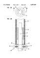
- FIG. 4 is a perspective view of an embodiment of an auger blade in accordance with the principles of the present invention.
- the fence post apparatus 10 includes a corner member 20 and two support members 40.
- the corner member 20 includes a post 22 and an auger base 32.
- the support members 40 each include a post 42 and auger base 52.
- the fence post apparatus 10 may further include braces 80 interconnected between the support posts 42 and the corner post 22. It is noted that the illustrated corner fence post apparatus 10 is exemplary only. The present invention extends to cover single fence posts, non-corner fence post apparatus, and corner fence post apparatus having any number of support posts.
- Corner member 20 includes a lower end portion 26 and a lower edge 28.
- the corner post 22 may be constructed of electrically insulating material suitable for use in electric fencing system, for example, fiberglass or polyvinylchloride (PVC) tubing.
- the corner post 22 may have an outer diameter of one and one-quarter to three inches with a wall thickness of one-eighth to one-half of an inch.
- the corner post 22 may be constructed of wood or metals such as steel or wrought iron.
- the corner auger base 32 typically includes an elongated shaft 34 and a helical blade 36.
- the shaft 34 may be constructed of any suitable material, including steel, or a corrosion resistant material and may have a diameter of one-half of an inch to two inches, for example.
- the length of shaft 34 will vary with its desired depth, and may be, for example, 36 inches. Extensions 55 may be added to allow deeper penetration into the ground for greater holding power.
- the shaft 34 may include a beveled end 38, and the helical blade 36 may be provided with a rounded leading edge 37, as best shown in FIG. 4.
- the shaft 34 of the auger base 32 may be coupled to the lower portion 26 of the corner post 22 using any number of coupling arrangements, including bonding, riveting, bolting, press-fitting, etc.
- the auger base 32 is received by the corner post 22 and connected thereto using a fastener 35, such as a bolt or pin, for example.
- the fastener 35 may be disposed through a bore 33 in the auger shaft 34 and a bore 25 in the corner post 22.
- the diameter of the fastener 35 and bores 33 and 25 may be on the order of five-sixteenths of an inch, for example.
- the shaft 34 is provided with an upper end portion 31 having a non-circular cross-section area which is less than the cross-sectional area of the shaft 34.
- the non-circular cross-section may be near-rectangular, as exemplified in FIG. 3A.
- the upper end portion 31 meets the body of the shaft 34, and there is formed a lip 39, the purpose of which will become apparent hereinbelow.
- the corner post 22 is provided with a reinforced portion 90 at its lower end portion 26.
- the reinforced portion 90 is a plastic insert, which may be bonded to the interior of corner post 22.
- the reinforced portion 90 may be a nonplastic insert or may be integrally molded with the corner post 22.
- the plastic insert may comprise a series of ribs 92 separated by grooves 94, the outer edge of the ribs 92 forming an inner surface which substantially mates with the outer surface of the shaft 34 to align the bores 33, 25.
- an upper portion 96 of the plastic insert may be provided with a non-circular cross-sectional area which mates with the cross-sectional area of the upper end portion 31 of the shaft 34. This forces the corner post 22 to receive the shaft 34 such that the bores 33, 25 are in substantial horizontal alignment.
- the lowermost edge 97 of the upper portion 96 forms a notch which mates with the lip 39 of the shaft 34 to vertically align the bores 33, 25.
- the reinforced portion 90 may be spaced from the lower edge 28 of the corner post 22, for example, by one inch. Use of a reinforced portion 90 generally increases the rigidity and durability of the corner post 22 and corner post 22/auger base 32 coupling, and, more specifically, prevents splitting of the corner post 22 near its lower edge 28 by reducing the stress concentration at the lower end portion 26.
- support members 40 include support posts 42 and auger bases 52, both of which may be constructed of materials similar to those used in constructing the corner post 22 and corner auger bases 32.
- Each support post 42 includes a top end portion 44, a lower end portion 46 and a lower edge 48.
- Each auger base 52 includes a shaft 54 and a helical blade 56. Similar to auger base 32, auger bases 52 may have a beveled end 58 and a helical blade 56 with a rounded leading edge 57.
- each support auger base 52 may be provided with an upper end portion 51 having a near-rectangular cross-sectional area and a bore so as to be interchangeable with corner post auger base 32.
- the top end portion 44 of the support post 42 may be coupled to the corner member 20 using a fastener, such as a U-shaped clamp member 84.
- the lower end portion 46 of the support post 42 may be coupled with the auger base 52 using any one of a variety of coupling arrangements.
- the auger shaft 54 is telescopically received by the support post 42, and adjustably coupled with the support post 42 using a stop assembly 60, for example, a ring with locking fasteners or a notch and rib assembly.
- the support post 42 may be provided with a reinforced portion 47 for receiving the auger shaft 52 and preventing splitting of the support post 42 as discussed earlier with the following difference: the support post reinforced portion 47 does not have an upper portion forming a ridge which would limit the depth to which the shaft 54 is received by the support post 42. This depth is adjustably limited by a stop assembly 60 as described hereinbelow.
- the stop assembly 60 comprises a ring 62 and at least one locking fastener, for example, a threaded bolt 64.
- the stop assembly 60 is disposed between the lower edge 48 of the support post 42 and the auger blade 56 and may be provided with a washer 66 disposed between the ring 62 and the support post 42 to more evenly distribute force around the perimeter of the lower edge 48 of the support post 42, to further prevent splitting of the lower edge 48 of the support post 42, and to prevent ring 62 from sliding into the support post 42.
- the stop assembly 60 may be slidably mountable on the auger shaft 54 for coupling the auger base 52 with the support post 42 and for adjusting the depth to which the auger shaft 54 is received by the support post 42. The depth may be adjusted by sliding the support post 42 and stop assembly 60 to a desired position and then securing the stop ring 62 to the shaft 54 by tightening the threaded bolts 64.
- the secured stop assembly 60 couples the auger base 52 with the support post 42 by preventing further movement of the auger shaft 54 with respect to the support post 42.
- the coupling or secure positioning results from the forces imparted on the fence post apparatus 10 by the fence wiring, i.e., the fence wiring forces impart an inward and downward force on the support posts 42 and stop assembly 60.
- the positional relationship between the support members 40 and the corner member 20 may be adjusted by sliding the support posts 42 and stop assemblies 60 rather than turning the support augers 52 further into or out of the ground or cutting the support auger shafts 54 and/or support posts 42 to a desired length.
- the support posts 42 may be easily positioned relative to the corner post such that the top ends 44 of the support posts 42 may be coupled to the corner post 22 through the use of a traditional fastener, such as a circular clamping member 82 or clamp and cap arrangement 85.
- the fence post apparatus 10 may further be provided with braces 80.
- Braces 80 may be horizontally positioned to and coupled between the corner post 22 and support posts 42. Braces 80 may be connected to the posts 22, 42 through the use of a suitable fastening device, such as a circular clamping member 82 as shown.
- the corner post 22 may be provided with wear plates 86 spaced apart along the perimeter of the corner post 22 and disposed between the corner post 22 and the fence wiring (not shown) to prevent wear on the corner post caused by movement of the fence wire.
- U-clips 88 may also be provided to retain the fence wire against the corner post 22 and maintain desired wire spacing.
Abstract
Description
Claims (16)
Priority Applications (2)
| Application Number | Priority Date | Filing Date | Title |
|---|---|---|---|
| US08/593,530 US5697600A (en) | 1996-01-24 | 1996-01-24 | Fence post apparatus |
| US08/961,161 US6126147A (en) | 1996-01-24 | 1997-10-30 | Fence post apparatus |
Applications Claiming Priority (1)
| Application Number | Priority Date | Filing Date | Title |
|---|---|---|---|
| US08/593,530 US5697600A (en) | 1996-01-24 | 1996-01-24 | Fence post apparatus |
Related Child Applications (1)
| Application Number | Title | Priority Date | Filing Date |
|---|---|---|---|
| US08/961,161 Continuation-In-Part US6126147A (en) | 1996-01-24 | 1997-10-30 | Fence post apparatus |
Publications (1)
| Publication Number | Publication Date |
|---|---|
| US5697600A true US5697600A (en) | 1997-12-16 |
Family
ID=24375091
Family Applications (1)
| Application Number | Title | Priority Date | Filing Date |
|---|---|---|---|
| US08/593,530 Expired - Fee Related US5697600A (en) | 1996-01-24 | 1996-01-24 | Fence post apparatus |
Country Status (1)
| Country | Link |
|---|---|
| US (1) | US5697600A (en) |
Cited By (10)
| Publication number | Priority date | Publication date | Assignee | Title |
|---|---|---|---|---|
| US5921035A (en) * | 1996-10-29 | 1999-07-13 | Kempf; Brian J. | Lockable screw post apparatus |
| US6126147A (en) * | 1996-01-24 | 2000-10-03 | Geotek, Inc. | Fence post apparatus |
| US6298611B1 (en) | 2000-05-17 | 2001-10-09 | James Oliver | Ground anchor with self-aligning compression cap |
| US6412235B1 (en) | 2000-09-08 | 2002-07-02 | Joseph T. Pylant | Removable screw-type, in-ground anchor device |
| US6412236B1 (en) * | 2000-12-01 | 2002-07-02 | Jeff Johnson | Easily installable fence post |
| GB2389872A (en) * | 2002-06-22 | 2003-12-24 | Charles John Viner | Fence post support |
| US6971209B1 (en) | 2003-04-28 | 2005-12-06 | Home Pride, Inc. | Stabilization system for an anchor and method of use thereof |
| US20060278800A1 (en) * | 2005-04-07 | 2006-12-14 | Simmons Robert J | Column plumb stabilizer |
| US20110031356A1 (en) * | 2009-08-06 | 2011-02-10 | Vonada Lowell L | Fastener |
| US10662669B2 (en) * | 2016-08-03 | 2020-05-26 | Kenneth Curt Anderson | Anchor fence post assembly |
Citations (12)
| Publication number | Priority date | Publication date | Assignee | Title |
|---|---|---|---|---|
| US299770A (en) * | 1884-06-03 | Fence | ||
| US598003A (en) * | 1898-01-25 | Revilo oliver | ||
| US755413A (en) * | 1903-04-28 | 1904-03-22 | stephen j Terry | Pole. |
| US1764207A (en) * | 1929-05-15 | 1930-06-17 | John G Johnson | Fence post |
| US1911483A (en) * | 1931-03-02 | 1933-05-30 | Inland Steel Co | End post and brace member |
| US3011598A (en) * | 1958-04-21 | 1961-12-05 | William H Galloway | Supporting post |
| FR1383253A (en) * | 1963-12-05 | 1964-12-24 | Screw anchor element | |
| CH635152A5 (en) * | 1979-01-22 | 1983-03-15 | Ughini Metallbau Ag | Crash barrier |
| US4803812A (en) * | 1987-11-23 | 1989-02-14 | Vsar Systems Of Atlanta, Inc. | Post ground anchor and method |
| US4923165A (en) * | 1988-05-02 | 1990-05-08 | Cockman Boyce R | Stabilized post anchor |
| US5011107A (en) * | 1990-03-15 | 1991-04-30 | Reece Roger R | Post anchor apparatus |
| US5139235A (en) * | 1991-07-26 | 1992-08-18 | Kilmer Willis G | Corner fence post system |
-
1996
- 1996-01-24 US US08/593,530 patent/US5697600A/en not_active Expired - Fee Related
Patent Citations (12)
| Publication number | Priority date | Publication date | Assignee | Title |
|---|---|---|---|---|
| US299770A (en) * | 1884-06-03 | Fence | ||
| US598003A (en) * | 1898-01-25 | Revilo oliver | ||
| US755413A (en) * | 1903-04-28 | 1904-03-22 | stephen j Terry | Pole. |
| US1764207A (en) * | 1929-05-15 | 1930-06-17 | John G Johnson | Fence post |
| US1911483A (en) * | 1931-03-02 | 1933-05-30 | Inland Steel Co | End post and brace member |
| US3011598A (en) * | 1958-04-21 | 1961-12-05 | William H Galloway | Supporting post |
| FR1383253A (en) * | 1963-12-05 | 1964-12-24 | Screw anchor element | |
| CH635152A5 (en) * | 1979-01-22 | 1983-03-15 | Ughini Metallbau Ag | Crash barrier |
| US4803812A (en) * | 1987-11-23 | 1989-02-14 | Vsar Systems Of Atlanta, Inc. | Post ground anchor and method |
| US4923165A (en) * | 1988-05-02 | 1990-05-08 | Cockman Boyce R | Stabilized post anchor |
| US5011107A (en) * | 1990-03-15 | 1991-04-30 | Reece Roger R | Post anchor apparatus |
| US5139235A (en) * | 1991-07-26 | 1992-08-18 | Kilmer Willis G | Corner fence post system |
Cited By (11)
| Publication number | Priority date | Publication date | Assignee | Title |
|---|---|---|---|---|
| US6126147A (en) * | 1996-01-24 | 2000-10-03 | Geotek, Inc. | Fence post apparatus |
| US5921035A (en) * | 1996-10-29 | 1999-07-13 | Kempf; Brian J. | Lockable screw post apparatus |
| US6298611B1 (en) | 2000-05-17 | 2001-10-09 | James Oliver | Ground anchor with self-aligning compression cap |
| US6412235B1 (en) | 2000-09-08 | 2002-07-02 | Joseph T. Pylant | Removable screw-type, in-ground anchor device |
| US6412236B1 (en) * | 2000-12-01 | 2002-07-02 | Jeff Johnson | Easily installable fence post |
| GB2389872A (en) * | 2002-06-22 | 2003-12-24 | Charles John Viner | Fence post support |
| US6971209B1 (en) | 2003-04-28 | 2005-12-06 | Home Pride, Inc. | Stabilization system for an anchor and method of use thereof |
| US20060278800A1 (en) * | 2005-04-07 | 2006-12-14 | Simmons Robert J | Column plumb stabilizer |
| US8322106B2 (en) * | 2005-04-07 | 2012-12-04 | Conxtech, Inc. | Column plumb stabilizer |
| US20110031356A1 (en) * | 2009-08-06 | 2011-02-10 | Vonada Lowell L | Fastener |
| US10662669B2 (en) * | 2016-08-03 | 2020-05-26 | Kenneth Curt Anderson | Anchor fence post assembly |
Similar Documents
| Publication | Publication Date | Title |
|---|---|---|
| US5139235A (en) | Corner fence post system | |
| US6273390B1 (en) | Post holder with upright adjustment | |
| US5984587A (en) | Ground stabilization apparatus and method for installing an enlongated post | |
| US6722821B1 (en) | Helice pier post and method of installation | |
| US7438273B2 (en) | Anchor for securing an object to ground | |
| US4706921A (en) | Antenna post base support and method of installing same | |
| US6871455B1 (en) | Drive/auger anchor and stabilizer | |
| US5697600A (en) | Fence post apparatus | |
| US6666625B2 (en) | Retaining wall support posts | |
| US20060239764A1 (en) | Post anchor/adapter system | |
| US6126147A (en) | Fence post apparatus | |
| US20050167644A1 (en) | Fence post | |
| US6298618B1 (en) | Constructional support | |
| US20060022188A1 (en) | Fixture and mounting assembly for a fence post | |
| US20020166302A1 (en) | Footing for sound-barrier walls | |
| US5661932A (en) | Post anchor and method of installing a post | |
| US4052827A (en) | Ground anchor and foundation support | |
| AU661632B1 (en) | Locking footing socket to improve post implantation | |
| US20180371789A1 (en) | Fence Assembly and Method of Installing the Same | |
| US20220356724A1 (en) | Adjustable post anchor with auger ground support | |
| KR200496837Y1 (en) | Foundation structure for fixing wire mesh fence columns | |
| KR102059373B1 (en) | Support structure for fence and method of construction thereof | |
| US7594782B2 (en) | Integral retaining foot for rammed post or pole | |
| US6588164B1 (en) | Screed form stake | |
| US20090309007A1 (en) | Concrete form anchor device, system and method for forming trenches |
Legal Events
| Date | Code | Title | Description |
|---|---|---|---|
| FPAY | Fee payment |
Year of fee payment: 4 |
|
| REMI | Maintenance fee reminder mailed | ||
| LAPS | Lapse for failure to pay maintenance fees | ||
| STCH | Information on status: patent discontinuation |
Free format text: PATENT EXPIRED DUE TO NONPAYMENT OF MAINTENANCE FEES UNDER 37 CFR 1.362 |
|
| FP | Lapsed due to failure to pay maintenance fee |
Effective date: 20051216 |
|
| AS | Assignment |
Owner name: MEDALLION CAPITAL, INC., MINNESOTA Free format text: SECURITY AGREEMENT;ASSIGNOR:GEOTEK ACQUISITION COMPANY, LLC;REEL/FRAME:022203/0907 Effective date: 20090204 |
|
| AS | Assignment |
Owner name: GEOTEK, LLC, MINNESOTA Free format text: TERMINATION AND RELEASE OF SECURITY;ASSIGNOR:SECURED PARTY MEDALLION CAPITAL, INC.;REEL/FRAME:026234/0786 Effective date: 20101029 |
|
| AS | Assignment |
Owner name: JPMORGAN CHASE BANK, N.A., ILLINOIS Free format text: SECURITY INTEREST;ASSIGNOR:GEOTEK, LLC;REEL/FRAME:061424/0456 Effective date: 20221014 |