US5692812A - Brake regulator with double valve - Google Patents
Brake regulator with double valve Download PDFInfo
- Publication number
- US5692812A US5692812A US08/411,742 US41174295A US5692812A US 5692812 A US5692812 A US 5692812A US 41174295 A US41174295 A US 41174295A US 5692812 A US5692812 A US 5692812A
- Authority
- US
- United States
- Prior art keywords
- ball
- piston
- push rod
- seat
- valve means
- Prior art date
- Legal status (The legal status is an assumption and is not a legal conclusion. Google has not performed a legal analysis and makes no representation as to the accuracy of the status listed.)
- Expired - Fee Related
Links
- 239000012530 fluid Substances 0.000 abstract description 7
- 230000000694 effects Effects 0.000 description 2
- 230000001747 exhibiting effect Effects 0.000 description 1
Images


Classifications
-
- B—PERFORMING OPERATIONS; TRANSPORTING
- B60—VEHICLES IN GENERAL
- B60T—VEHICLE BRAKE CONTROL SYSTEMS OR PARTS THEREOF; BRAKE CONTROL SYSTEMS OR PARTS THEREOF, IN GENERAL; ARRANGEMENT OF BRAKING ELEMENTS ON VEHICLES IN GENERAL; PORTABLE DEVICES FOR PREVENTING UNWANTED MOVEMENT OF VEHICLES; VEHICLE MODIFICATIONS TO FACILITATE COOLING OF BRAKES
- B60T8/00—Arrangements for adjusting wheel-braking force to meet varying vehicular or ground-surface conditions, e.g. limiting or varying distribution of braking force
- B60T8/18—Arrangements for adjusting wheel-braking force to meet varying vehicular or ground-surface conditions, e.g. limiting or varying distribution of braking force responsive to vehicle weight or load, e.g. load distribution
- B60T8/1812—Arrangements for adjusting wheel-braking force to meet varying vehicular or ground-surface conditions, e.g. limiting or varying distribution of braking force responsive to vehicle weight or load, e.g. load distribution characterised by the means for pressure reduction
- B60T8/1831—Arrangements for adjusting wheel-braking force to meet varying vehicular or ground-surface conditions, e.g. limiting or varying distribution of braking force responsive to vehicle weight or load, e.g. load distribution characterised by the means for pressure reduction pressure reducing or limiting valves
-
- B—PERFORMING OPERATIONS; TRANSPORTING
- B60—VEHICLES IN GENERAL
- B60T—VEHICLE BRAKE CONTROL SYSTEMS OR PARTS THEREOF; BRAKE CONTROL SYSTEMS OR PARTS THEREOF, IN GENERAL; ARRANGEMENT OF BRAKING ELEMENTS ON VEHICLES IN GENERAL; PORTABLE DEVICES FOR PREVENTING UNWANTED MOVEMENT OF VEHICLES; VEHICLE MODIFICATIONS TO FACILITATE COOLING OF BRAKES
- B60T11/00—Transmitting braking action from initiating means to ultimate brake actuator without power assistance or drive or where such assistance or drive is irrelevant
- B60T11/10—Transmitting braking action from initiating means to ultimate brake actuator without power assistance or drive or where such assistance or drive is irrelevant transmitting by fluid means, e.g. hydraulic
- B60T11/28—Valves specially adapted therefor
- B60T11/34—Pressure reducing or limiting valves
-
- B—PERFORMING OPERATIONS; TRANSPORTING
- B60—VEHICLES IN GENERAL
- B60T—VEHICLE BRAKE CONTROL SYSTEMS OR PARTS THEREOF; BRAKE CONTROL SYSTEMS OR PARTS THEREOF, IN GENERAL; ARRANGEMENT OF BRAKING ELEMENTS ON VEHICLES IN GENERAL; PORTABLE DEVICES FOR PREVENTING UNWANTED MOVEMENT OF VEHICLES; VEHICLE MODIFICATIONS TO FACILITATE COOLING OF BRAKES
- B60T8/00—Arrangements for adjusting wheel-braking force to meet varying vehicular or ground-surface conditions, e.g. limiting or varying distribution of braking force
- B60T8/18—Arrangements for adjusting wheel-braking force to meet varying vehicular or ground-surface conditions, e.g. limiting or varying distribution of braking force responsive to vehicle weight or load, e.g. load distribution
- B60T8/1881—Arrangements for adjusting wheel-braking force to meet varying vehicular or ground-surface conditions, e.g. limiting or varying distribution of braking force responsive to vehicle weight or load, e.g. load distribution characterised by failure-responsive means
-
- Y—GENERAL TAGGING OF NEW TECHNOLOGICAL DEVELOPMENTS; GENERAL TAGGING OF CROSS-SECTIONAL TECHNOLOGIES SPANNING OVER SEVERAL SECTIONS OF THE IPC; TECHNICAL SUBJECTS COVERED BY FORMER USPC CROSS-REFERENCE ART COLLECTIONS [XRACs] AND DIGESTS
- Y10—TECHNICAL SUBJECTS COVERED BY FORMER USPC
- Y10T—TECHNICAL SUBJECTS COVERED BY FORMER US CLASSIFICATION
- Y10T137/00—Fluid handling
- Y10T137/7722—Line condition change responsive valves
- Y10T137/7837—Direct response valves [i.e., check valve type]
- Y10T137/7904—Reciprocating valves
- Y10T137/7922—Spring biased
- Y10T137/7927—Ball valves
- Y10T137/7928—With follower
Definitions
- the present invention relates to a brake regulator, intended to be interposed between a source of hydraulic pressure and a braking circuit of a motor vehicle and including a casing provided with at least one bore; a hydraulic piston sliding in this bore and therein delimiting first and second pressure chambers separated from one another by valve means carried by this piston, the first and second chambers being capable of being connected respectively to the source of pressure and to the braking circuit; and a push rod acting on the valve means in a direction capable of allowing the opening thereof when a relatively low pressure prevails in the second chamber, the piston sliding in the bore, under the action of an increase in pressure in this second chamber, in a direction capable of moving the push rod away from the valve means and correspondingly allowing closure thereof, these valve means comprising a first ball of predetermined diameter, urged by a first spring in the direction both of the push rod and of a first seat formed inside the piston.
- the object of the invention is to propose a silent and robust regulator, capable of operating without failure, even in the absence of a filter for the brake fluid.
- the regulator of the invention is essentially characterized in that the valve means comprise a second ball interposed between the first ball and the push rod, interacting with a second seat formed inside the piston, and urged by a second spring in the direction both of the push rod and of the second seat, this second ball being moved away from the second seat by the push rod and itself moving the first ball away from the first seat when a relatively low pressure prevails in the second chamber, and the distance separating the two balls, when they are applied to their respective seats, being less than the possible sliding travel of the piston in the bore.
- the valve means comprise a second ball interposed between the first ball and the push rod, interacting with a second seat formed inside the piston, and urged by a second spring in the direction both of the push rod and of the second seat, this second ball being moved away from the second seat by the push rod and itself moving the first ball away from the first seat when a relatively low pressure prevails in the second chamber, and the distance separating the two balls, when they are applied to their respective seats, being less than the possible sliding travel of
- the second spring is compressed between the two balls and the two springs exhibit different stiffnesses, the stiffness of the second spring being less than that of the first, and the second ball exhibits a diameter less than the diameter of the first ball.
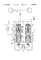
- FIG. 1 is an overall sectional view of a regulator in accordance with the invention
- FIG. 2 is an enlarged detail view of a part of FIG. 1, representing the piston in a first position
- FIG. 3 is an enlarged detail view of a part of FIG. 1, representing the piston in a second position;
- FIG. 4 is an enlarged detail view of a part of FIG. 1, representing the piston in a third position;
- FIG. 5 is an enlarged detail view of a part of FIG. 1, representing a second possible embodiment of the piston.
- FIG. 6 is an enlarged detail view of a part of FIG. 1, representing a third possible embodiment of the piston.
- the invention relates to a brake regulator 1, intended to be interposed between a source of hydraulic pressure, such as a master cylinder 2, and the rear brake circuit 3 of a motor vehicle, so as to supply to this brake circuit 3 a pressure equal to the output pressure of the source of pressure for the low values of this pressure, and a pressure less than that of the source for higher values of the latter.
- a source of hydraulic pressure such as a master cylinder 2
- the rear brake circuit 3 of a motor vehicle so as to supply to this brake circuit 3 a pressure equal to the output pressure of the source of pressure for the low values of this pressure, and a pressure less than that of the source for higher values of the latter.
- This regulator comprises, in a way which is conventional, a casing 10 provided with at least one bore 11, a hydraulic piston 12 sliding in this bore and therein delimiting first and second pressure chambers 13 and 14 separated from one another by valve means 15 carried by this piston 12.
- the regulator in fact comprises two bores 11 and 11a, the components housed in the bore 11a being similar in every respect to those which are housed in the bore 11 and identified by the same reference numeral, apart from the "a" index.
- first and second chambers 13, 14 are respectively connected to the source of pressure 2 and the brake circuit 3.
- a push rod 16 connected to the casing 1 acts on the valve means 15 in a direction capable of allowing opening thereof where relatively low pressure prevails in the second chamber 14, and the piston 12 slides in the bore 11, under the effect of a rise in pressure in this second chamber 14, in a direction capable of moving the valve means 15 away from the push rod 16 and correspondingly allowing closure thereof.
- the piston 12 is, for example, a differential piston exhibiting, in the first chamber 13 on the opposite side from the second 14, a pressure section defined by a bore 110 and less than that of the bore 11.
- valve means 15 comprise a first ball 151 of predetermined diameter, urged by a first spring 153 in the direction both of the push rod 16 and of a first seat 155 formed inside the piston.
- valve means moreover comprise a second ball 152 which, in FIGS. 1 to 4, is represented with a diameter less than the diameter of the first ball 151, which is interposed between this first ball 151 and the push rod 16, which interacts with a second seat 156 formed inside the piston, and which is urged by a second spring 154 in the direction both of the push rod 16 and of the second seat 156.
- FIG. 2 represents the position adopted by the valve means 15 relative to the push rod 16 when a relatively low pressure prevails in the second chamber 14, and shows that the second ball 152 is then moved away from the second seat 156 by the push rod 16 and that it itself moves the first ball 151 away from the first seat 155.
- FIG. 3 represents the position adopted by the valve means 15 relative to the push rod 16 when the pressure prevailing in the second chamber 14 has increased sufficiently, owing to an increase in pressure in the first chamber 13, for the first ball 151 to close off the first seat 155.
- the brake fluid present in the first chamber continues to migrate into the second chamber and to increase the pressure in the latter.
- the second spring 154 is preferably compressed between the two balls 151 and 152, the second spring then having to have a stiffness less than that of the first spring 153 so that the first and second balls become applied to their seat in the desired order, illustrated by the figures.
- FIGS. 5 and 6 show that it is equally possible to give the second ball 152 the same diameter as that of the first ball (FIG. 5), or even a greater diameter (FIG. 6), these embodiments however requiring the addition of an additional component 157 bearing the seat 155 for the first ball 151.
- the presence of the latter divides the pressure difference existing between the first and second pressure chambers 13 and 14 into a first pressure drop brought about by the first ball 151 and its seat 155, and a second pressure drop brought about by the second ball 152 and its seat 156.
Landscapes
- Engineering & Computer Science (AREA)
- Transportation (AREA)
- Mechanical Engineering (AREA)
- Valves And Accessory Devices For Braking Systems (AREA)
- Hydraulic Control Valves For Brake Systems (AREA)
- Transmission Of Braking Force In Braking Systems (AREA)
Abstract
Description
Claims (4)
Applications Claiming Priority (3)
| Application Number | Priority Date | Filing Date | Title |
|---|---|---|---|
| FR9404624 | 1994-04-19 | ||
| FR9404624A FR2718695B1 (en) | 1994-04-19 | 1994-04-19 | Braking corrector with double valve. |
| PCT/FR1995/000322 WO1995028308A1 (en) | 1994-04-19 | 1995-03-17 | Dual valve braking corrector |
Publications (1)
| Publication Number | Publication Date |
|---|---|
| US5692812A true US5692812A (en) | 1997-12-02 |
Family
ID=9462231
Family Applications (1)
| Application Number | Title | Priority Date | Filing Date |
|---|---|---|---|
| US08/411,742 Expired - Fee Related US5692812A (en) | 1994-04-19 | 1995-03-17 | Brake regulator with double valve |
Country Status (7)
| Country | Link |
|---|---|
| US (1) | US5692812A (en) |
| EP (1) | EP0752943B1 (en) |
| JP (1) | JP3619938B2 (en) |
| DE (1) | DE69502717T2 (en) |
| ES (1) | ES2117860T3 (en) |
| FR (1) | FR2718695B1 (en) |
| WO (1) | WO1995028308A1 (en) |
Cited By (1)
| Publication number | Priority date | Publication date | Assignee | Title |
|---|---|---|---|---|
| US6439263B2 (en) * | 1999-12-24 | 2002-08-27 | Robert Bosch Gmbh | Pressure regulating valve and method for producing a pressure regulating valve |
Citations (12)
| Publication number | Priority date | Publication date | Assignee | Title |
|---|---|---|---|---|
| US2793656A (en) * | 1953-09-29 | 1957-05-28 | Electrol Inc | Relief valve |
| US3345998A (en) * | 1965-02-19 | 1967-10-10 | Gianni A Dotto | Safety check valve |
| US3447564A (en) * | 1967-05-31 | 1969-06-03 | Brunswick Corp | Leakproof valve |
| US3684328A (en) * | 1970-08-19 | 1972-08-15 | Gen Motors Corp | Brake anti-lock modulator with bypass valve |
| US3900230A (en) * | 1974-05-13 | 1975-08-19 | Midland Ross Corp | Pneumatic brake system incorporating a double check valve |
| US4060283A (en) * | 1976-11-11 | 1977-11-29 | General Motors Corporation | Brake actuating pressure proportioning system and proportioner modifying arm therefor |
| US4101176A (en) * | 1975-04-01 | 1978-07-18 | Societe Anonyme Dba | Braking correction device |
| EP0335764A1 (en) * | 1988-03-30 | 1989-10-04 | BENDIX EUROPE Services Techniques S.A. | Load sensitive brake force corrector with vehicle height sensor |
| EP0461420A1 (en) * | 1990-06-15 | 1991-12-18 | Robert Bosch Gmbh | Pressure switch for hydraulic vehicle brake systems with traction control |
| US5215359A (en) * | 1990-05-16 | 1993-06-01 | Alfred Teves Gmbh | Hydraulic anti-locking brake unit |
| US5246277A (en) * | 1991-05-07 | 1993-09-21 | Jidosha Kiki Co., Ltd. | Liquid pressure control device for load responding brake |
| US5472266A (en) * | 1991-10-18 | 1995-12-05 | Itt Automotive Europe Gmbh | Anti-lock hydraulic brake system |
-
1994
- 1994-04-19 FR FR9404624A patent/FR2718695B1/en not_active Expired - Fee Related
-
1995
- 1995-03-17 DE DE69502717T patent/DE69502717T2/en not_active Expired - Fee Related
- 1995-03-17 EP EP95913208A patent/EP0752943B1/en not_active Expired - Lifetime
- 1995-03-17 WO PCT/FR1995/000322 patent/WO1995028308A1/en not_active Ceased
- 1995-03-17 JP JP52655995A patent/JP3619938B2/en not_active Expired - Fee Related
- 1995-03-17 US US08/411,742 patent/US5692812A/en not_active Expired - Fee Related
- 1995-03-17 ES ES95913208T patent/ES2117860T3/en not_active Expired - Lifetime
Patent Citations (13)
| Publication number | Priority date | Publication date | Assignee | Title |
|---|---|---|---|---|
| US2793656A (en) * | 1953-09-29 | 1957-05-28 | Electrol Inc | Relief valve |
| US3345998A (en) * | 1965-02-19 | 1967-10-10 | Gianni A Dotto | Safety check valve |
| US3447564A (en) * | 1967-05-31 | 1969-06-03 | Brunswick Corp | Leakproof valve |
| US3684328A (en) * | 1970-08-19 | 1972-08-15 | Gen Motors Corp | Brake anti-lock modulator with bypass valve |
| US3900230A (en) * | 1974-05-13 | 1975-08-19 | Midland Ross Corp | Pneumatic brake system incorporating a double check valve |
| US4101176A (en) * | 1975-04-01 | 1978-07-18 | Societe Anonyme Dba | Braking correction device |
| US4060283A (en) * | 1976-11-11 | 1977-11-29 | General Motors Corporation | Brake actuating pressure proportioning system and proportioner modifying arm therefor |
| EP0335764A1 (en) * | 1988-03-30 | 1989-10-04 | BENDIX EUROPE Services Techniques S.A. | Load sensitive brake force corrector with vehicle height sensor |
| US5215359A (en) * | 1990-05-16 | 1993-06-01 | Alfred Teves Gmbh | Hydraulic anti-locking brake unit |
| EP0461420A1 (en) * | 1990-06-15 | 1991-12-18 | Robert Bosch Gmbh | Pressure switch for hydraulic vehicle brake systems with traction control |
| US5181768A (en) * | 1990-06-15 | 1993-01-26 | Robert Bosch Gmbh | Pressure switch valve, for hydraulic vehicle brake systems with traction control (asr) |
| US5246277A (en) * | 1991-05-07 | 1993-09-21 | Jidosha Kiki Co., Ltd. | Liquid pressure control device for load responding brake |
| US5472266A (en) * | 1991-10-18 | 1995-12-05 | Itt Automotive Europe Gmbh | Anti-lock hydraulic brake system |
Cited By (1)
| Publication number | Priority date | Publication date | Assignee | Title |
|---|---|---|---|---|
| US6439263B2 (en) * | 1999-12-24 | 2002-08-27 | Robert Bosch Gmbh | Pressure regulating valve and method for producing a pressure regulating valve |
Also Published As
| Publication number | Publication date |
|---|---|
| FR2718695A1 (en) | 1995-10-20 |
| JPH09511962A (en) | 1997-12-02 |
| EP0752943B1 (en) | 1998-05-27 |
| DE69502717T2 (en) | 1998-11-26 |
| WO1995028308A1 (en) | 1995-10-26 |
| FR2718695B1 (en) | 1996-06-07 |
| JP3619938B2 (en) | 2005-02-16 |
| EP0752943A1 (en) | 1997-01-15 |
| ES2117860T3 (en) | 1998-08-16 |
| DE69502717D1 (en) | 1998-07-02 |
Similar Documents
| Publication | Publication Date | Title |
|---|---|---|
| US5729979A (en) | Variable rate brake pedal feel emulator | |
| US3493270A (en) | Impulse check valve | |
| EP0360378B1 (en) | Vehicle braking systems | |
| US6014862A (en) | Emulator damping mechanism | |
| GB2120333A (en) | Hydraulic brake booster | |
| US6846408B2 (en) | Filter assembly for a control valve in a vehicular brake system | |
| US3972192A (en) | Tandem master cylinder | |
| US5692812A (en) | Brake regulator with double valve | |
| EP0130297A1 (en) | Fast-fill master cylinder | |
| JPH04300765A (en) | Two circuit brake gear | |
| WO1992003321A3 (en) | Linear variable pressure adaptive braking and traction control system | |
| US4390213A (en) | Deceleration-sensitive braking pressure control device | |
| US5046316A (en) | Tandem master cylinder with filters arranged in central valves | |
| US4058348A (en) | Brake apparatus with a combined brake cylinder and reservoir | |
| US3684329A (en) | Load responsive hydraulic pressure control mechanism of an automotive vehicle | |
| EP1175321B1 (en) | Brake proportioning in-line ball valve | |
| US4432586A (en) | Anti-skid brake control system for motor vehicles | |
| US5205621A (en) | Brake-pressure reduction means for a motor vehicle | |
| US3453029A (en) | Pressure sensitive metering valve | |
| US4542945A (en) | Deceleration-sensitive braking pressure control unit for a vehicular hydraulic brake system | |
| US6217132B1 (en) | Hydraulic control unit having a master cylinder and anti-lock braking valves integrally mounted therein | |
| CA1172939A (en) | Fluid pressure proportioning valve | |
| JPH0147334B2 (en) | ||
| JP2772542B2 (en) | Hydraulic proportioning valve | |
| EP0157467A2 (en) | Multi-circuit fluid pressure control valve |
Legal Events
| Date | Code | Title | Description |
|---|---|---|---|
| AS | Assignment |
Owner name: ALLIEDSIGNAL AUTOMOTIVE ESPANA S.A., SPAIN Free format text: ASSIGNMENT OF ASSIGNORS INTEREST;ASSIGNOR:BARCARDIT, JUAN SIMON;REEL/FRAME:008297/0195 Effective date: 19950317 |
|
| FEPP | Fee payment procedure |
Free format text: PAYOR NUMBER ASSIGNED (ORIGINAL EVENT CODE: ASPN); ENTITY STATUS OF PATENT OWNER: LARGE ENTITY |
|
| FPAY | Fee payment |
Year of fee payment: 4 |
|
| FPAY | Fee payment |
Year of fee payment: 8 |
|
| REMI | Maintenance fee reminder mailed | ||
| LAPS | Lapse for failure to pay maintenance fees | ||
| LAPS | Lapse for failure to pay maintenance fees |
Free format text: PATENT EXPIRED FOR FAILURE TO PAY MAINTENANCE FEES (ORIGINAL EVENT CODE: EXP.); ENTITY STATUS OF PATENT OWNER: LARGE ENTITY |
|
| STCH | Information on status: patent discontinuation |
Free format text: PATENT EXPIRED DUE TO NONPAYMENT OF MAINTENANCE FEES UNDER 37 CFR 1.362 |
|
| FP | Lapsed due to failure to pay maintenance fee |
Effective date: 20091202 |