US5690740A - High volume low pressure air entrapment of overspray - Google Patents
High volume low pressure air entrapment of overspray Download PDFInfo
- Publication number
- US5690740A US5690740A US08/588,761 US58876196A US5690740A US 5690740 A US5690740 A US 5690740A US 58876196 A US58876196 A US 58876196A US 5690740 A US5690740 A US 5690740A
- Authority
- US
- United States
- Prior art keywords
- air
- work surface
- chisel
- low pressure
- high volume
- Prior art date
- Legal status (The legal status is an assumption and is not a legal conclusion. Google has not performed a legal analysis and makes no representation as to the accuracy of the status listed.)
- Expired - Lifetime
Links
- 239000007921 spray Substances 0.000 claims abstract description 90
- 238000005507 spraying Methods 0.000 claims description 35
- 239000007788 liquid Substances 0.000 claims description 25
- 239000000843 powder Substances 0.000 claims description 20
- 230000006698 induction Effects 0.000 claims description 9
- 238000000576 coating method Methods 0.000 claims description 8
- 239000011248 coating agent Substances 0.000 claims description 7
- 239000000463 material Substances 0.000 abstract description 17
- 239000012530 fluid Substances 0.000 description 13
- 238000010586 diagram Methods 0.000 description 8
- 239000012855 volatile organic compound Substances 0.000 description 8
- 239000007787 solid Substances 0.000 description 7
- 238000000034 method Methods 0.000 description 6
- 239000000443 aerosol Substances 0.000 description 5
- 239000002245 particle Substances 0.000 description 4
- 230000001629 suppression Effects 0.000 description 4
- 238000000889 atomisation Methods 0.000 description 3
- 230000000694 effects Effects 0.000 description 3
- 239000007789 gas Substances 0.000 description 3
- 238000004519 manufacturing process Methods 0.000 description 3
- 239000000203 mixture Substances 0.000 description 3
- 239000012188 paraffin wax Substances 0.000 description 3
- 239000002904 solvent Substances 0.000 description 3
- 230000008901 benefit Effects 0.000 description 2
- 230000008878 coupling Effects 0.000 description 2
- 238000010168 coupling process Methods 0.000 description 2
- 238000005859 coupling reaction Methods 0.000 description 2
- 230000007613 environmental effect Effects 0.000 description 2
- 239000002360 explosive Substances 0.000 description 2
- 238000005259 measurement Methods 0.000 description 2
- 230000008569 process Effects 0.000 description 2
- 239000000758 substrate Substances 0.000 description 2
- 230000000153 supplemental effect Effects 0.000 description 2
- 230000033228 biological regulation Effects 0.000 description 1
- 230000001276 controlling effect Effects 0.000 description 1
- 230000002939 deleterious effect Effects 0.000 description 1
- 238000009472 formulation Methods 0.000 description 1
- 239000003517 fume Substances 0.000 description 1
- 230000002068 genetic effect Effects 0.000 description 1
- 230000036541 health Effects 0.000 description 1
- 230000002401 inhibitory effect Effects 0.000 description 1
- 239000003595 mist Substances 0.000 description 1
- 239000003973 paint Substances 0.000 description 1
- 230000001105 regulatory effect Effects 0.000 description 1
- 239000000126 substance Substances 0.000 description 1
- 231100000331 toxic Toxicity 0.000 description 1
- 230000002588 toxic effect Effects 0.000 description 1
Images


Classifications
-
- B—PERFORMING OPERATIONS; TRANSPORTING
- B05—SPRAYING OR ATOMISING IN GENERAL; APPLYING FLUENT MATERIALS TO SURFACES, IN GENERAL
- B05B—SPRAYING APPARATUS; ATOMISING APPARATUS; NOZZLES
- B05B12/00—Arrangements for controlling delivery; Arrangements for controlling the spray area
- B05B12/16—Arrangements for controlling delivery; Arrangements for controlling the spray area for controlling the spray area
- B05B12/18—Arrangements for controlling delivery; Arrangements for controlling the spray area for controlling the spray area using fluids, e.g. gas streams
-
- B—PERFORMING OPERATIONS; TRANSPORTING
- B05—SPRAYING OR ATOMISING IN GENERAL; APPLYING FLUENT MATERIALS TO SURFACES, IN GENERAL
- B05B—SPRAYING APPARATUS; ATOMISING APPARATUS; NOZZLES
- B05B12/00—Arrangements for controlling delivery; Arrangements for controlling the spray area
- B05B12/16—Arrangements for controlling delivery; Arrangements for controlling the spray area for controlling the spray area
- B05B12/32—Shielding elements, i.e. elements preventing overspray from reaching areas other than the object to be sprayed
- B05B12/36—Side shields, i.e. shields extending in a direction substantially parallel to the spray jet
Definitions
- This invention relates to atomization and application of fluids, such as paints, to a surface and to apparatus which minimizes loss of such fluids into the atmosphere.
- Airless spraying equipment operate using pressures of 1800 to 2500 psig. Through the use of hydraulic pressure, fluid is conveyed to a spraying apparatus where it is forced through a small orifice. The high pressure by which it is propelled is responsible for "bounceback" whereby the fluid literally bounces back into the atmosphere of the work place. The fluid contaminates the environment, the worker, and the equipment.
- the most prominent method of spraying a liquid or a powder is to use a high pressure gas, such as air, to entrain and carry the liquid or powder to a substrate or target.
- a high pressure gas such as air
- the high pressure gas explodes into the atmosphere creating a turbulence and finely pulverizes the solids.
- This turbulence dispenses the particles over a large area producing a deleterious fog or mist of toxic fumes and harmful solids.
- the danger to the worker, to the environment and to cost containment is obvious.
- a conventional pneumatic spraying apparatus use high pressure, low volume compressor air at 50 to 60 psig and 4 or 5 cfm in concert with an air regulator to atomize fluids. Spraying with such an apparatus produces a wasteful cloud of fluid and air commonly referred to as "overspray".
- Overspray is created by the explosive expansion of the mixture of solids, liquids, and gas at the nozzle of the spray gun. Overspray contains an aerosol of fluid drops and solid particles including drops of 5 to 35 microns in diameter. Solvents in the fluid being sprayed are referred to as volatile organic compounds (VOC). VOC entrained in overspray rapidly evaporates. The VOC become part of the atmosphere and present a hazard to the environment and to the operator. Overspray also may be generated from the spraying of powders, in which case the overspray consists of an aerosol of solid particles.
- HVLP high volume low pressure
- HPLV high pressure low volume
- Air at 30 psi and 80 cfm would be classed as HVLP air, while air at 80 psi and 30 cfm would be classed as HPLV air.
- HVLP air typically EPA approved HVLP air is at a pressure of up to 10 psi and a volume of up to 30 cfm.
- HVLP spraying reduces the incident of bounceback because the fluid sprayed contacts the target surface at a relatively low velocity. HVLP spraying reduces the incidence of overspray because the explosive expansive atomization of fluid which produces the aerosol is minimized when low pressure air is used.
- overspray is used as a genetic term which includes bounceback and overspray as described above, and is sometimes called errant spray. This generic usage will be used here.
- Transfer efficiency is a measurement used for comparing methods of atomization. T.E. is expressed as a percentage of the solid substances sprayed that become part of a substrate or arrive at the intended target.
- Conventional pneumatic spraying has a T.E. of 25%; airless spraying has a T.E. of 40%; and HVLP spraying has a T.E. of 75%.
- the Environmental Protection Agency has expressed special concern about the hazards associated with airborne particles of a diameter of 10 microns or less (PM 10 ). That Agency has established regulations controlling PM 10 concentrations in outdoor applications, such as shipbuilding, bridges, towers, and architectural coatings. The production of PM 10 is virtually uncontrollable when conventional spraying or airless methods are used.
- VOC is often regulated in terms of tons VOC/day emitted per site.
- a typical spray booth is ventilated by a flow of air at 150 ft 3 /minute per ft 2 surface being painted.
- the contaminated air is then treated to remove the VOC and PM 10 , often by incineration, a very expensive process.
- the present invention uses directed HVLP air emitted from an elongated nozzle, termed an "air chisel", to entrap overspray onto the target surface and prevent the entry of overspray into the environment.
- U.S. Pat. No. 2,438,471 discloses a curtain of air introduced around the spray nozzle which traps the rebounding portions of the coating mixture and forces it against the surface being coated.
- the air curtain is emitted through a series of holes in an annular air chamber extending entirely around the spray nozzle.
- U.S. Pat. No. 1,897,173 discloses a cap like spray nozzle in which a central stream of liquid is surrounded by an annular air port.
- the liquid stream is modified by two opposed supplemental air ports which shape the emitted spray into a fairly sharply defined ellipsoid cross-section.
- the streams of air from the supplemental air ports form a tubular air sheath surrounding the liquid stream which forms the liquid stream into a fan-shaped spray.
- U.S. Pat. No. 2,101,922 discloses an apparatus for spraying melted paraffin onto porous surfaces.
- the stream of paraffin is surrounded by a sheath of heated air.
- One venturi arrangement is used to atomize and propel the paraffin in a stream of air while a second concentric venturi is used to provide the sheath of heated, low-pressure air.
- U.S. Pat. No. 5,062,572 discloses an agricultural liquid sprayer having a wind shield to prevent disruption of the spray pattern by employing the wind to the advantage of the sprayer.
- the wind shield is in the shape of a horn which captures a side wind and directs it in the direction of the spray pattern.
- U.S. Pat. No. 5,393,345, incorporated herein by reference, discloses an apparatus for having a jet venturi induction pump and respray nozzle mounted near the front of a sprayer. Overspray is captured by the induction ports of the induction pump and redeposited on the work surface.
- This invention uses an oriented air curtain to contain and trap overspray and prevent the entry of overspray into the atmosphere.
- the air curtain is generated from HVLP air by a nozzle unit comprised of an elongated nozzle, a bore, and a conduit for LPHV air.
- the nozzle unit and oriented air curtain taken together are termed an "air chisel”.
- the plume or profile of the area of impact of the sprayed material with the work surface, is typically in the shape of an elongated ellipse, with a long axis along the longest dimension of the plume, and a short axis along the shortest dimension of the ellipse.
- the air curtain formed by the elongated nozzle is also in the shape of an elongated ellipse, having a long and a short axis.
- the long axis of the plume is approximately parallel to the long axis of the air curtain.
- the air curtain is emitted from the nozzle or nozzles mounted at the side of the spray nozzle and directed inwardly toward the plume.
- the air chisel gently blows the overspray back against the work surface, thereby reducing escape of overspray into the atmosphere and at the same time producing a better coating on the sprayed work surface.
- the objective of this invention is to reduce the emission of overspray into the atmosphere associated with spraying of atomizable liquid or powder.
- Another objective is to provide a sprayed work surface having superior coating.
- Another objective is to economize on the use of atomizable liquid or powder by maximizing the coating obtained from a given quantity of material sprayed.
- Another objective is to increase the production rate of sprayed objects.
- Another objective is to protect the health of operatives by inhibiting the generation of aerosols of material sprayed.
- Another objective is to reduce the quantity of airflow required to protect the operatives from overspray generated at a work surface.
- Another objective is to reduce the requirement for respirator use by operatives.
- Another objective is to provide a spray gun having a shield which directs the air chisel toward the work surface and which increases the effectiveness of the air chisel in suppressing overspray.
- Another objective is to provide a spray apparatus which functions in an efficient, effective manner with minimal environmental impact.
- FIG. 1 is a diagram showing the suppression of overspray by two air chisels.
- FIG. 2 is a diagram showing the spray plume and the air plumes of FIG. 1.
- FIG. 3A is a diagram showing the generation of overspray by a spray gun spraying on a work surface.
- FIG. 3B is a diagram showing the suppression by air chisels of overspray generated by a spray gun spraying on a work surface.
- FIG. 4 is a side view of a spray gun with attached nozzle unit.
- FIG. 5 is a front view of a spray gun with two attached nozzle units.
- FIG. 6 is a side view of a nozzle unit attached to a stand.
- FIG. 7 is a side view of a nozzle unit having a jet induction pump attached to a stand.
- FIG. 8 is a side view of multiple nozzle units attached to a bar.
- FIG. 9 is a front view of multiple nozzle units attached to a bar.
- FIG. 10 is a side view of an operator spraying a work object in a spray booth with multiple nozzle units mounted on a bar and attached to the spray booth.
- FIG. 11 is a top view of the operator spraying a work object of FIG. 9.
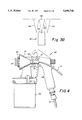
- FIG. 12 is side view of a second embodiment spray gun with attached nozzle unit having a shield.
- FIG. 13 is a diagram showing suppression of overspray by two air chisels in a second embodiment spray gun with attached nozzle unit having a shield.
- FIG. 1 is a diagrammatic side view of a spray gun with two attached nozzle units.
- a spray gun 30 sprays atomizable liquid or powder 50 from a spray nozzle 33 onto a work surface 46. The generation of a small amount of overspray 52 is shown.
- An air chisel consists of a nozzle unit 12 in combination with an oriented air curtain 54.
- the nozzle unit 13 emits HVLP air from an elongated nozzle 23 in an air curtain 55 which forms an ellipse-like shape or air plume 55 on contact with the work surface 46.
- the air plume is adjacent to the ellipse-like shaped spray plume 51, which is the shape of the contact of the sprayed liquid or powder and the surface of the work.
- the elongated air plume is parallel and adjacent to the spray plume.
- the relationship between the air curtains of the air chisels and the spray plume of the sprayed material is shown in FIG. 2.
- the sprayed plume 51 has a long axis 53 and a short axis 56.
- Each air plume 55 has a long axis 57 and a short axis 59.
- the long axis 57 of each air plume 55 is approximately parallel to the long axis 53 of the spray plume 51.
- FIG. 1 shows the orientation of the air curtain 54 with respect to the work surface 46.
- a line 63 is drawn perpendicular to the work surface 46.
- the air curtain 54 is inclined to the line 63 at an angle 65 which is from 10° to about 80° to the line 63.
- Each nozzle unit 12 consists of an elongated nozzle 23, a bore 10, and a conduit or hose 21 which provides HVLP air.
- each nozzle unit 12 is attached to the spray gun 30 by a ring 34 which surrounds the barrel of the spray gun
- Two spray gun posts 38 are attached to the ring on opposite sides of the spray gun.
- An adjustable coupling 36 connects the spray gun posts 38 to the nozzle unit post 37.
- Each nozzle unit post 37 is connected to the respective bore 10 by a nozzle unit ring 39.
- the adjustable coupling 36 allows the orientation of the air curtain to be varied as desired.
- the effect of the air chisels is to inhibit, contain, and retard the development of overspray 52. In this process, the loss of sprayed material to overspray and the generation of VOC is inhibited. In addition, the effect of the air curtains causes the sprayed material to form a smoother, finer finish on the work surface.
- the orientation of the air curtains with respect to the work surface may be varied depending on the nature of the sprayed liquid or powder.
- a relatively light sprayed material of low viscosity liquid will use an orientation in which the air curtain is approximately parallel or at a relatively small inclination, 10°, to a line perpendicular to the work surface.
- the use of a relatively heavy or highly viscous sprayed material will require the orientation of the air curtain at a greater angle, up to 80° to the line perpendicular to the work surface.
- FIG. 3A is a diagram showing a spray gun 30 which emits sprayed material 50 from a nozzle 33.
- the sprayed material 50 contacts the work surface 46 with the generation of overspray 52.
- This invention may be used with spray guns which use HVLP or HPLV or airless spraying systems.
- the maximum overspray is generated with HPLV spraying.
- a lesser amount of overspray is generated with HVLP spraying; and a minimum with airless spraying; but all systems generated overspray.
- FIG. 3B is a diagram showing the effect of air curtains 54 on the overspray 52 of FIG. 3A generated by spraying sprayed material 50 from the nozzle 33 of a spray gun 30 on a work surface 46.
- the overspray is eliminated.
- the sprayed material of the overspray is deposited on the work surface and is not emitted into the atmosphere.
- FIG. 4 is a side view of a spray gun with a nozzle unit attached.
- the spray gun 30 has an air hose 31 for provision of atomizing air and a reservoir 32 which holds the material to be sprayed, atomizable fluid or powder. The sprayed material is emitted by the nozzle 33.
- a nozzle unit 12 is attached to each side of the spray gun.
- the air curtain is emitted from the elongated nozzle 23 which is attached to the bore 10.
- HVLP air is provided to the bore through a hose or conduit 21. HVLP air passes from the conduit through the bore and is emitted by the elongated nozzle.
- the nozzle unit 12 is attached to the spray gun by a barrel ring 34 which, in turn, is attached to a bore ring 39.
- FIG. 5 is a front view of the spray gun 30 of FIG. 4.
- the reservoir 32 is omitted for clarity.
- the nozzle is at 32.
- the air hose 31 provides air to the spray gun.
- the air source 40 provides air to the spray gun 30 and also to the nozzle units 12 of the air chisels.
- the air source may provide the spray gun with HVLP air or with HPLV air.
- the HVLP air source also provides the air chisels with HVLP air. If the spray gun uses HPVL air, the air chisels may be provided with HVLP air from an air compressor, air turbine, or air blower. When the spray gun uses the airless method of spraying, no air source is necessary for the spray gun; the air chisels may be provided with HVLP air as above.
- the barrel ring 34 which attaches the nozzle units 12 to the spray gun 30, the elongated nozzles 23, and the hose or conduit 21 which provides LPHV air to the nozzle units.
- FIG. 6 is a side view of a nozzle unit mounted on a stand.
- the nozzle unit 12 consisting of an elongated nozzle 23, a bore 10, and a hose 21, is connected by a bore ring 39 to the stand post 64, which is mounted on the stand base 66.
- FIG. 7 is a side view of a nozzle unit having a jet venturi pump mounted on a stand.
- the nozzle unit 12 consisting of an elongated nozzle 23, a bore 10, a jet venturi pump between the bore and the hose 14 which has three visible induction ports 17, and a hose 21, is connected by a bore ring 39 to the stand post 64, which is mounted on the stand base 66.
- a nozzle unit having a jet venturi pump, as in FIG. 7, has the additional advantage of respraying any overspray which may reach the jet venturi induction pump.
- the overspray is induced into the induction ports 17 and resprayed from the elongated nozzle.
- FIG. 8 is a top view of a mounting bar having four mounted nozzle units.
- the nozzle units 12 consisting of elongated nozzles 23, bores 10, and hoses 21 are mounted by bore rings on a mounting bar 60.
- Other means for attaching the nozzle units to a mounting bar may be used, such as nuts and bolts, screws, etc.
- FIG. 9 is a front view of the mounting bar having four mounted nozzle units of FIG. 8. Visible are the mounting bar 60, nozzle units 12, and elongated nozzles 23.
- FIG. 10 is a side view of an operator 42 who is spraying a work object 44 using a spray gun 30 having a reservoir 32 and an air hose 31 which is connected to a compressor 40.
- the work object 44 rests on a horizontal support 48 in a spray area 46.
- Four nozzle units 12 mounted on a mounting bar 60 are mounted by a attachment bar 62 to the front of the spray area 46.
- the nozzle units are provided with HVLP air by a hose 21 from the air compressor 40.
- the nozzle units are mounted close enough to the work object to provide an oriented air curtain which contains and suppresses overspray, thus functioning as air chisels.
- a second similar group of four air chisels are not visible in FIG. 10 but are visible in FIG. 11.
- FIG. 11 is at top view of the scene of FIG. 10. both groups of mounted nozzle unit, the one on the left side 63 and on the right side 64 of the spray gun 30 are shown. Also shown in FIG. 11 is the sprayed material 50 emitted from the spray gun and the air curtains 54 emitted from the nozzle units.
- FIG. 12 is a side view of a second embodiment of a spray gun with a nozzle unit attached.
- a shield 70 is interposed between the nozzle unit 12 and the spray gun 30.
- the orientation of the shield is approximately parallel to the air curtain.
- the other elements of the second embodiment spray gun of FIG. 13 are as in FIG. 4.
- the function of the shield 70 is to direct the flow of HVLP air emitted from the nozzle unit 12 and aid in the repression of bounceback.
- FIG. 13 is a diagram showing suppression of bounce back by air chisels in a second embodiment spray gun having shields 70 and 72 between the spray plum 50 and the oriented air curtains 54.
- the shields 70 and 72 are mounted on the spray gun posts 38.
- the other elements of the second embodiment spray gun of FIG. 12 are as in FIG. 1.
- the air curtains 54 are deflected by shields 70 and 72 and directed toward the work surface 46 where they suppress overspray 52.
- Shields 70 and 72 also act to prevent disruption of air curtains 54 or of spray of atomizable liquid or powder 50 by any air currents 72 which are approximately parallel to the work surface 46. Such air currents 72 are redirected by shield 70 and incorporated into air curtain 54.
Landscapes
- Nozzles (AREA)
Abstract
Description
Claims (20)
Priority Applications (1)
| Application Number | Priority Date | Filing Date | Title |
|---|---|---|---|
| US08/588,761 US5690740A (en) | 1996-01-19 | 1996-01-19 | High volume low pressure air entrapment of overspray |
Applications Claiming Priority (1)
| Application Number | Priority Date | Filing Date | Title |
|---|---|---|---|
| US08/588,761 US5690740A (en) | 1996-01-19 | 1996-01-19 | High volume low pressure air entrapment of overspray |
Publications (1)
| Publication Number | Publication Date |
|---|---|
| US5690740A true US5690740A (en) | 1997-11-25 |
Family
ID=24355194
Family Applications (1)
| Application Number | Title | Priority Date | Filing Date |
|---|---|---|---|
| US08/588,761 Expired - Lifetime US5690740A (en) | 1996-01-19 | 1996-01-19 | High volume low pressure air entrapment of overspray |
Country Status (1)
| Country | Link |
|---|---|
| US (1) | US5690740A (en) |
Cited By (12)
| Publication number | Priority date | Publication date | Assignee | Title |
|---|---|---|---|---|
| US6264711B1 (en) | 1999-11-24 | 2001-07-24 | William Smith | Capture of liquid sanding dust atomized overspray blast media and other errant particles in an unenclosed area |
| FR2824000A1 (en) | 2001-04-27 | 2002-10-31 | Christian Guilhem | METHOD AND INSTALLATION FOR TREATING OBJECTS BY MANUAL SPRAY OF FOG WITH PROTECTIVE AIR CURTAIN |
| US20050161861A1 (en) * | 2003-09-26 | 2005-07-28 | Brunswick Corporation | Apparatus and method for making preforms in mold |
| US20070238028A1 (en) * | 2004-04-20 | 2007-10-11 | Tokyo Electron Limited | Substrate Treatment Method and Substrate Treatment Apparatus |
| US20070295210A1 (en) * | 2006-06-22 | 2007-12-27 | Smith William C | Portable system for capturing air pollution |
| WO2008047205A2 (en) | 2006-10-18 | 2008-04-24 | Illinois Tool Works, Inc. | Spray masks and line markers |
| US20100020297A1 (en) * | 2003-06-06 | 2010-01-28 | Tokyo Electron Limited | Method for improving surface roughness of processed film of substrate and apparatus for processing substrate |
| US20100288427A1 (en) * | 2007-12-26 | 2010-11-18 | Asahi Fiber Glass Company, Limited | Process for production of inorganic fiber mats |
| CN103111403A (en) * | 2013-03-11 | 2013-05-22 | 苏州斯莱克精密设备股份有限公司 | Vacuum drainage device of easy-open lids dividing coating machine |
| CN108970826A (en) * | 2017-05-31 | 2018-12-11 | 耐克创新有限合伙公司 | Nozzle, material dispensing system and the method for applying material from nozzle |
| US10414670B2 (en) * | 2015-08-24 | 2019-09-17 | Global Water Farms Corporation | Systems and methods for distillation of water from seawater, brackish water, waste waters, and effluent waters |
| CN111246944A (en) * | 2017-10-18 | 2020-06-05 | 福伊特专利有限公司 | Curtain coating mechanism and method for coating a coating medium |
Citations (7)
| Publication number | Priority date | Publication date | Assignee | Title |
|---|---|---|---|---|
| US1897173A (en) * | 1931-04-29 | 1933-02-14 | Binks Mfg Co | Air nozzle for spray appliances |
| US2101922A (en) * | 1935-02-19 | 1937-12-14 | Stoesling Ludwig | Spraying apparatus |
| US2438471A (en) * | 1944-06-05 | 1948-03-23 | Briggs Mfg Co | Spraying apparatus |
| US4850809A (en) * | 1988-04-14 | 1989-07-25 | Smith William C | Air operated low pressure spraying system |
| US4857367A (en) * | 1987-10-16 | 1989-08-15 | Thorn Brent A | Method of and apparatus for spraying |
| US5062572A (en) * | 1989-11-07 | 1991-11-05 | F. P. Bourgault Industries | Spray shield |
| US5393345A (en) * | 1993-11-30 | 1995-02-28 | Smith; William C. | Respray of overspray of any atomizable liquid with jet venturi induction pump |
-
1996
- 1996-01-19 US US08/588,761 patent/US5690740A/en not_active Expired - Lifetime
Patent Citations (7)
| Publication number | Priority date | Publication date | Assignee | Title |
|---|---|---|---|---|
| US1897173A (en) * | 1931-04-29 | 1933-02-14 | Binks Mfg Co | Air nozzle for spray appliances |
| US2101922A (en) * | 1935-02-19 | 1937-12-14 | Stoesling Ludwig | Spraying apparatus |
| US2438471A (en) * | 1944-06-05 | 1948-03-23 | Briggs Mfg Co | Spraying apparatus |
| US4857367A (en) * | 1987-10-16 | 1989-08-15 | Thorn Brent A | Method of and apparatus for spraying |
| US4850809A (en) * | 1988-04-14 | 1989-07-25 | Smith William C | Air operated low pressure spraying system |
| US5062572A (en) * | 1989-11-07 | 1991-11-05 | F. P. Bourgault Industries | Spray shield |
| US5393345A (en) * | 1993-11-30 | 1995-02-28 | Smith; William C. | Respray of overspray of any atomizable liquid with jet venturi induction pump |
Cited By (24)
| Publication number | Priority date | Publication date | Assignee | Title |
|---|---|---|---|---|
| US6264711B1 (en) | 1999-11-24 | 2001-07-24 | William Smith | Capture of liquid sanding dust atomized overspray blast media and other errant particles in an unenclosed area |
| FR2824000A1 (en) | 2001-04-27 | 2002-10-31 | Christian Guilhem | METHOD AND INSTALLATION FOR TREATING OBJECTS BY MANUAL SPRAY OF FOG WITH PROTECTIVE AIR CURTAIN |
| WO2002087780A1 (en) | 2001-04-27 | 2002-11-07 | Christian Guilhem | Method and installation for treating objects by manual spraying of mist with protective air curtain |
| US8646403B2 (en) * | 2003-06-06 | 2014-02-11 | Tokyo Electron Limited | Method for improving surface roughness of processed film of substrate and apparatus for processing substrate |
| US20100020297A1 (en) * | 2003-06-06 | 2010-01-28 | Tokyo Electron Limited | Method for improving surface roughness of processed film of substrate and apparatus for processing substrate |
| US20050161861A1 (en) * | 2003-09-26 | 2005-07-28 | Brunswick Corporation | Apparatus and method for making preforms in mold |
| US20100316961A1 (en) * | 2004-04-20 | 2010-12-16 | Tokyo Electon Limited | Substrate treatment method and substrate treatment apparatus |
| US20070238028A1 (en) * | 2004-04-20 | 2007-10-11 | Tokyo Electron Limited | Substrate Treatment Method and Substrate Treatment Apparatus |
| US7819076B2 (en) * | 2004-04-20 | 2010-10-26 | Tokyo Electron Limited | Substrate treatment method and substrate treatment apparatus |
| US7989156B2 (en) | 2004-04-20 | 2011-08-02 | Tokyo Electron Limited | Substrate treatment method and substrate treatment apparatus |
| US20070295210A1 (en) * | 2006-06-22 | 2007-12-27 | Smith William C | Portable system for capturing air pollution |
| US7550022B2 (en) * | 2006-06-22 | 2009-06-23 | Smith William C | Portable system for capturing air pollution |
| WO2008047205A2 (en) | 2006-10-18 | 2008-04-24 | Illinois Tool Works, Inc. | Spray masks and line markers |
| WO2008047205A3 (en) * | 2006-10-18 | 2008-07-31 | Illinois Tool Works | Spray masks and line markers |
| US20100288427A1 (en) * | 2007-12-26 | 2010-11-18 | Asahi Fiber Glass Company, Limited | Process for production of inorganic fiber mats |
| US8404063B2 (en) * | 2007-12-26 | 2013-03-26 | Asahi Glass Company, Limited | Process for production of inorganic fiber mats |
| CN103111403A (en) * | 2013-03-11 | 2013-05-22 | 苏州斯莱克精密设备股份有限公司 | Vacuum drainage device of easy-open lids dividing coating machine |
| CN103111403B (en) * | 2013-03-11 | 2015-04-15 | 苏州斯莱克精密设备股份有限公司 | Vacuum drainage device of easy-open lids dividing coating machine |
| US10414670B2 (en) * | 2015-08-24 | 2019-09-17 | Global Water Farms Corporation | Systems and methods for distillation of water from seawater, brackish water, waste waters, and effluent waters |
| CN108970826A (en) * | 2017-05-31 | 2018-12-11 | 耐克创新有限合伙公司 | Nozzle, material dispensing system and the method for applying material from nozzle |
| US20220097083A1 (en) * | 2017-05-31 | 2022-03-31 | Nike, Inc. | Air Masking Nozzle |
| US12220713B2 (en) * | 2017-05-31 | 2025-02-11 | Nike, Inc. | Air masking nozzle |
| CN111246944A (en) * | 2017-10-18 | 2020-06-05 | 福伊特专利有限公司 | Curtain coating mechanism and method for coating a coating medium |
| CN111246944B (en) * | 2017-10-18 | 2022-06-10 | 福伊特专利有限公司 | Curtain coating mechanism and method for coating a coating medium |
Similar Documents
| Publication | Publication Date | Title |
|---|---|---|
| US5690740A (en) | High volume low pressure air entrapment of overspray | |
| US5271564A (en) | Spray gun extension | |
| US5487695A (en) | Blast nozzle combined with multiple tip water atomizer | |
| CA1085240A (en) | Apparatus and method for spray application of solvent- thinned coating compositions | |
| EP0650766B1 (en) | Suction feed nozzle assembly for HVLP spray gun | |
| US5393345A (en) | Respray of overspray of any atomizable liquid with jet venturi induction pump | |
| EP0075018B1 (en) | Atomizing or dispersion nozzle | |
| EP0378741B1 (en) | Improved paint spray nozzle | |
| US4762274A (en) | Inductor nozzle assembly for crop sprayers | |
| EP0157872A4 (en) | Rotary atomizer spray painting device. | |
| GB2128106A (en) | Electrostatic sprayhead assembly | |
| US12440860B2 (en) | System and method for coating a surface | |
| GB2111406A (en) | Spray gun | |
| JPH0761462B2 (en) | Electrostatic liquid spray coating of a coating sprayed from an orifice using a supercritical fluid as a diluent | |
| US3635400A (en) | Paint spraying method and apparatus | |
| US20070194157A1 (en) | Method and apparatus for high transfer efficiency electrostatic spray | |
| US4850809A (en) | Air operated low pressure spraying system | |
| US5527564A (en) | Method and apparatus for repelling overspray in spray paint booths | |
| US4542855A (en) | Agricultural spraying device | |
| US3861594A (en) | Apparatus and method for simultaneously painting both sides of a wire fence | |
| US3747852A (en) | Paint spraying method | |
| EP0222622A2 (en) | Inductor nozzle assembly for crop sprayers | |
| GB2170981A (en) | Spraying of agricultural chemicals | |
| JPH11244735A (en) | Spray equipment of coating, mortar or the like | |
| EP0474635A1 (en) | Plant spraying apparatus and method |
Legal Events
| Date | Code | Title | Description |
|---|---|---|---|
| STCF | Information on status: patent grant |
Free format text: PATENTED CASE |
|
| FEPP | Fee payment procedure |
Free format text: PAYOR NUMBER ASSIGNED (ORIGINAL EVENT CODE: ASPN); ENTITY STATUS OF PATENT OWNER: SMALL ENTITY |
|
| FEPP | Fee payment procedure |
Free format text: PAYOR NUMBER ASSIGNED (ORIGINAL EVENT CODE: ASPN); ENTITY STATUS OF PATENT OWNER: SMALL ENTITY Free format text: PAYER NUMBER DE-ASSIGNED (ORIGINAL EVENT CODE: RMPN); ENTITY STATUS OF PATENT OWNER: SMALL ENTITY |
|
| FPAY | Fee payment |
Year of fee payment: 4 |
|
| FEPP | Fee payment procedure |
Free format text: PAYER NUMBER DE-ASSIGNED (ORIGINAL EVENT CODE: RMPN); ENTITY STATUS OF PATENT OWNER: SMALL ENTITY |
|
| FPAY | Fee payment |
Year of fee payment: 8 |
|
| FPAY | Fee payment |
Year of fee payment: 12 |
|
| AS | Assignment |
Owner name: WILLIAM CHARLES SMITH REVOCABLE TRUST, MARYLAND Free format text: ASSIGNMENT OF ASSIGNORS INTEREST;ASSIGNOR:SMITH, WILLIAM C.;REEL/FRAME:030406/0651 Effective date: 20121209 |