US568675A - Williams - Google Patents
Williams Download PDFInfo
- Publication number
- US568675A US568675A US568675DA US568675A US 568675 A US568675 A US 568675A US 568675D A US568675D A US 568675DA US 568675 A US568675 A US 568675A
- Authority
- US
- United States
- Prior art keywords
- circuit
- armature
- drum
- conducting
- transmitter
- Prior art date
- Legal status (The legal status is an assumption and is not a legal conclusion. Google has not performed a legal analysis and makes no representation as to the accuracy of the status listed.)
- Expired - Lifetime
Links
- 230000033001 locomotion Effects 0.000 description 19
- 230000007246 mechanism Effects 0.000 description 19
- 239000003550 marker Substances 0.000 description 18
- BASFCYQUMIYNBI-UHFFFAOYSA-N platinum Chemical compound [Pt] BASFCYQUMIYNBI-UHFFFAOYSA-N 0.000 description 12
- 239000000976 ink Substances 0.000 description 11
- 229910052751 metal Inorganic materials 0.000 description 9
- 239000002184 metal Substances 0.000 description 9
- 239000000463 material Substances 0.000 description 8
- 230000033458 reproduction Effects 0.000 description 8
- 238000000034 method Methods 0.000 description 6
- 229910052697 platinum Inorganic materials 0.000 description 6
- 239000004020 conductor Substances 0.000 description 4
- 230000000875 corresponding effect Effects 0.000 description 4
- 238000005530 etching Methods 0.000 description 4
- 239000000203 mixture Substances 0.000 description 4
- 108010010803 Gelatin Proteins 0.000 description 3
- 206010021703 Indifference Diseases 0.000 description 3
- YXFVVABEGXRONW-UHFFFAOYSA-N Toluene Chemical compound CC1=CC=CC=C1 YXFVVABEGXRONW-UHFFFAOYSA-N 0.000 description 3
- 239000010426 asphalt Substances 0.000 description 3
- SOCTUWSJJQCPFX-UHFFFAOYSA-N dichromate(2-) Chemical compound [O-][Cr](=O)(=O)O[Cr]([O-])(=O)=O SOCTUWSJJQCPFX-UHFFFAOYSA-N 0.000 description 3
- 239000012634 fragment Substances 0.000 description 3
- 229920000159 gelatin Polymers 0.000 description 3
- 239000008273 gelatin Substances 0.000 description 3
- 235000019322 gelatine Nutrition 0.000 description 3
- 235000011852 gelatine desserts Nutrition 0.000 description 3
- 239000003292 glue Substances 0.000 description 3
- 150000002739 metals Chemical class 0.000 description 3
- 230000001105 regulatory effect Effects 0.000 description 3
- 238000005096 rolling process Methods 0.000 description 3
- UHOVQNZJYSORNB-UHFFFAOYSA-N Benzene Chemical compound C1=CC=CC=C1 UHOVQNZJYSORNB-UHFFFAOYSA-N 0.000 description 2
- 244000286663 Ficus elastica Species 0.000 description 2
- 239000000899 Gutta-Percha Substances 0.000 description 2
- RRHGJUQNOFWUDK-UHFFFAOYSA-N Isoprene Chemical compound CC(=C)C=C RRHGJUQNOFWUDK-UHFFFAOYSA-N 0.000 description 2
- 240000000342 Palaquium gutta Species 0.000 description 2
- 238000004140 cleaning Methods 0.000 description 2
- 238000010276 construction Methods 0.000 description 2
- 238000010586 diagram Methods 0.000 description 2
- 229920000588 gutta-percha Polymers 0.000 description 2
- 230000010355 oscillation Effects 0.000 description 2
- 229920001195 polyisoprene Polymers 0.000 description 2
- 230000000630 rising effect Effects 0.000 description 2
- XLYOFNOQVPJJNP-UHFFFAOYSA-N water Substances O XLYOFNOQVPJJNP-UHFFFAOYSA-N 0.000 description 2
- QGZKDVFQNNGYKY-UHFFFAOYSA-O Ammonium Chemical compound [NH4+] QGZKDVFQNNGYKY-UHFFFAOYSA-O 0.000 description 1
- 101100168093 Caenorhabditis elegans cogc-2 gene Proteins 0.000 description 1
- XFXPMWWXUTWYJX-UHFFFAOYSA-N Cyanide Chemical compound N#[C-] XFXPMWWXUTWYJX-UHFFFAOYSA-N 0.000 description 1
- 101100163433 Drosophila melanogaster armi gene Proteins 0.000 description 1
- 241000237907 Echiura Species 0.000 description 1
- DGAQECJNVWCQMB-PUAWFVPOSA-M Ilexoside XXIX Chemical compound C[C@@H]1CC[C@@]2(CC[C@@]3(C(=CC[C@H]4[C@]3(CC[C@@H]5[C@@]4(CC[C@@H](C5(C)C)OS(=O)(=O)[O-])C)C)[C@@H]2[C@]1(C)O)C)C(=O)O[C@H]6[C@@H]([C@H]([C@@H]([C@H](O6)CO)O)O)O.[Na+] DGAQECJNVWCQMB-PUAWFVPOSA-M 0.000 description 1
- 101100221487 Mus musculus Cog2 gene Proteins 0.000 description 1
- ZLMJMSJWJFRBEC-UHFFFAOYSA-N Potassium Chemical compound [K] ZLMJMSJWJFRBEC-UHFFFAOYSA-N 0.000 description 1
- KWYUFKZDYYNOTN-UHFFFAOYSA-M Potassium hydroxide Chemical compound [OH-].[K+] KWYUFKZDYYNOTN-UHFFFAOYSA-M 0.000 description 1
- BQCADISMDOOEFD-UHFFFAOYSA-N Silver Chemical compound [Ag] BQCADISMDOOEFD-UHFFFAOYSA-N 0.000 description 1
- 230000005540 biological transmission Effects 0.000 description 1
- 238000001311 chemical methods and process Methods 0.000 description 1
- 230000002596 correlated effect Effects 0.000 description 1
- 230000007547 defect Effects 0.000 description 1
- WXNGUMYXVIWRMY-WAIOZSTDSA-N depressin Chemical compound C1C\C(C)=C\C(=O)CC(/C)=C/CC(=O)\C(C)=C\C2C(C)(C)C12 WXNGUMYXVIWRMY-WAIOZSTDSA-N 0.000 description 1
- MCPLVIGCWWTHFH-UHFFFAOYSA-M disodium;4-[4-[[4-(4-sulfoanilino)phenyl]-[4-(4-sulfonatophenyl)azaniumylidenecyclohexa-2,5-dien-1-ylidene]methyl]anilino]benzenesulfonate Chemical compound [Na+].[Na+].C1=CC(S(=O)(=O)O)=CC=C1NC1=CC=C(C(=C2C=CC(C=C2)=[NH+]C=2C=CC(=CC=2)S([O-])(=O)=O)C=2C=CC(NC=3C=CC(=CC=3)S([O-])(=O)=O)=CC=2)C=C1 MCPLVIGCWWTHFH-UHFFFAOYSA-M 0.000 description 1
- 230000000694 effects Effects 0.000 description 1
- 210000003746 feather Anatomy 0.000 description 1
- 239000004833 fish glue Substances 0.000 description 1
- -1 five parts Polymers 0.000 description 1
- PCHJSUWPFVWCPO-UHFFFAOYSA-N gold Chemical compound [Au] PCHJSUWPFVWCPO-UHFFFAOYSA-N 0.000 description 1
- 229910052737 gold Inorganic materials 0.000 description 1
- 239000010931 gold Substances 0.000 description 1
- 238000010438 heat treatment Methods 0.000 description 1
- 238000009413 insulation Methods 0.000 description 1
- 230000002452 interceptive effect Effects 0.000 description 1
- 229940072033 potash Drugs 0.000 description 1
- 229910052700 potassium Inorganic materials 0.000 description 1
- 239000011591 potassium Substances 0.000 description 1
- 235000015320 potassium carbonate Nutrition 0.000 description 1
- BWHMMNNQKKPAPP-UHFFFAOYSA-L potassium carbonate Substances [K+].[K+].[O-]C([O-])=O BWHMMNNQKKPAPP-UHFFFAOYSA-L 0.000 description 1
- 239000000843 powder Substances 0.000 description 1
- 229950003857 propizepine Drugs 0.000 description 1
- 238000007790 scraping Methods 0.000 description 1
- 229910052709 silver Inorganic materials 0.000 description 1
- 239000004332 silver Substances 0.000 description 1
- 229910052708 sodium Inorganic materials 0.000 description 1
- 239000011734 sodium Substances 0.000 description 1
- 239000007787 solid Substances 0.000 description 1
- 239000002904 solvent Substances 0.000 description 1
- 230000001360 synchronised effect Effects 0.000 description 1
Images


Classifications
-
- H—ELECTRICITY
- H04—ELECTRIC COMMUNICATION TECHNIQUE
- H04N—PICTORIAL COMMUNICATION, e.g. TELEVISION
- H04N1/00—Scanning, transmission or reproduction of documents or the like, e.g. facsimile transmission; Details thereof
- H04N1/024—Details of scanning heads ; Means for illuminating the original
- H04N1/032—Details of scanning heads ; Means for illuminating the original for picture information reproduction
-
- Y—GENERAL TAGGING OF NEW TECHNOLOGICAL DEVELOPMENTS; GENERAL TAGGING OF CROSS-SECTIONAL TECHNOLOGIES SPANNING OVER SEVERAL SECTIONS OF THE IPC; TECHNICAL SUBJECTS COVERED BY FORMER USPC CROSS-REFERENCE ART COLLECTIONS [XRACs] AND DIGESTS
- Y10—TECHNICAL SUBJECTS COVERED BY FORMER USPC
- Y10T—TECHNICAL SUBJECTS COVERED BY FORMER US CLASSIFICATION
- Y10T409/00—Gear cutting, milling, or planing
- Y10T409/50—Planing
- Y10T409/500164—Planing with regulation of operation by templet, card, or other replaceable information supply
- Y10T409/500328—Planing with regulation of operation by templet, card, or other replaceable information supply including use of tracer adapted to trigger electrical or fluid energy
- Y10T409/500492—Planing with regulation of operation by templet, card, or other replaceable information supply including use of tracer adapted to trigger electrical or fluid energy including provision for circumferential relative movement of cutter and work
Definitions
- the present invention relates to improvements in automatic apparatus for the reproduction at a distant receiving-station, by meansof regulated electric currents, of facsimiles of manuscripts, sketches, pictures, and other analogous graphie or pictorial matter (hereinafter referred to as vthe design) previously in existence at the transmittingstation.
- My invention includes (A) an improved con ⁇ struction of transmitter especially in respect of the contact-finger; (B) improvements in the conducting-surface of the transmitter; (C) improved inks for the imposition of the design upon the conductingsurface; (D) means for facilitating the imposition of the design upon the conducting-surface; (E) mechanism for keeping the conducting-surface of the transmitter clean; (F) improved means for regulating the local currents at the receiving-station by means of the linecurrent; (G) an improved tool or graver for the receiver; (H) various improved combinations of electrical or mechanical agencies.
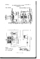
- Figure 1 is an end elevation of the transmitter and includes a diagram of a portion of its circuit.
- Fig. 2 is a front elevation of the transmitter.
- Fig. 3 is a plan corresponding'with Figs. 1 and 2.
- Fig. l is an end elevation of the receiver, including a diagram of the remaining portion of the transmitter-circuit, the relay, and the receiver-circuit.
- Fig. 5 is a front elevation of the same.
- Fig. 6 is a plan corresponding with Figs. Ll and 5.
- Fig. 7 is an end elevation of a transmitter fitted with the improved conducting-surface and mechanism for keeping such surface clean.
- Fig. 8 is a front elevation corresponding with Fig. 7.
- Figs. 9, lO, and 11 illustrate a modified type of graver.
- Trcmsm'tterf-'lhe transmitter consists of an electric circuit which includes a conducting-surface, a contact-iin ger, the line-Wire, and the electromagnet of a relay. These members of the apparatus, excepting the lastmentioned magnet, are illustrated in Figs. 1, 2, and 3.
- the condnoting-surface may be that oi a metal drum rotated at a regular speed about its axis, the contact-finger being traversed over the drum in a line parallel with its axis. rlhe linger is traversed by means of a leading-screw engaging in the arm which carries it, the said screw being rotated about its axis, but without linear motion.
- the width of the finger-tip and the relative speeds of the drum and screw are so apportioned that the trace of the :linger upon the drum shall be a closed, or nearly closed, spiral, or, in other words, that every point of the conducting-surface shall successively pass the linger-tip afore said once during the traverse of the latter from one end of the axis of the said surface to the other.
- the linger may be stationaryr and the drinn receive a linear motion equivalent to its length in addition to the motion of rotation described under (c).
- the conducting-surface may be that of a (lat table capable of a reciprocating linear motion at right angles to that oi the traverse of the linger.
- lVhichcver method may be adopted, it is obviously a sin@ qua non that every point of the cont'lncting surface shall successively pass the linger-tip or the linger-tip pass over practically the whole of it during their mutual traverse.
- Any suitable motor maybe made use of for the purpose of rotating the drum and leading-screw aforesaid or for otherwise effecting the mutual traverse of the conducting-surface and the linger-tip.
- A is a parallel metal drum and its perimeter receives the conducting-surface of the transmitter. This drum is fast upon a shaft a, the journals of which are supported in bearings a a', carried by a pair of standards a2 ai, set opposite te each other and at a suitable distance apart upon a VIirm base o.
- i3 is the contact-linger. It is a round stem or rod capable of a to-and-:fro vertical motion through a socket turned in the end of a jib b, the base of which is made fast to asad die b', litted to embrace a double-V bed o?, upon which it can slide to and fro.
- This bed is alincd parallel with the axis and surface of the drum A, and the jib t) overhangs the latter just far enough forthe axis of the contact-linger l to be exactljT over the axis of the drinn.
- the bed U3 is carried by standards c c', which are set opposite to each other and at a suitable distance apart upon the base a. above mentioned.
- C is a leading-screw.
- lts journals are sup ported in bearings c c, carried by the standards c c.
- the leading-screw is parallel with.
- ri ⁇ he spring l1 is suiliciently weak to yield before the :resistance offered by the material of the design and strong enough to ellect the quick depression or return to the condnoting-surface of the drum A of the tip ofthe contact-linger l. TWith reference to the construction of the tip of the contact-tinger it must be pointed out that it is necessary to make special provision against its riv ⁇ ing u p the design material when the two come into contact and pass eachother, ⁇ for if a fragment of such material were rived up by the tip it might maintain non-contact between the tip and the comluctingsurface for the remainder of the time the transmitter' was at work, and would do so until such time as the tip cleared itself.
- the contact between the tip and ma terial is always of a rolling nature, inasmuch as the tip consists of a small wheel if, (herciir ait'terward called the contact-1'oller,) free to turn upon an axis in the bottom end of the lin ger.
- the said axis is parallel with the axis oi' the drum A, and consequently th c ⁇ wheel which constitutes the linger-tip works in a plane at right angles with the lastunentiened axis.
- the one illustrated in the figures consists of a screw-pin h6, screwed through the fingersocket in a radial direction and standing with its latnose close up to, but not touching, the faceof a vertical flat surface 67, formed upon the adjacent side of the nger B and long enough to allow of the necessary up-anddown motion of the iinger-tip b5.
- the conducting-surface of the transmitter may be of either platinum, silver, or gold.
- the selected metal may be .either solid or deposited. l find that neither of these three metals oxidizes when there is sparking between the roller-Wheel of contact-finger and the conducting-surface to the same extent as most other metals. For the same reason the said roller-wheel is made of the same metal (one of the three specified above) as the conducting-surface.
- Inks The insulating-inks which have been proposed up to the present time possess properties which unfit them' more or less for use in connection with apparatus of the type forming the subject of the present invention.
- One reason is that they are generally too brittle to resist the pull of the end of the contact-roller as it passes over the matter, and consequently small pieces of the latter are rived up and remain on the said roller and so maintain it in a more or less insulated condition, or the said pieces are dropped onto the transmitter-surface, Where they would be likely to act as partof the imposed design.
- I make a suitable ink by dissolving india-rubber, gutta-percha, and bitumen in benzin,
- bitumen (preferably in the form of fine powder, as generally used for half-tone process photographic reproductions,) twelve parts, by weight; pure india-rubber, five parts, and gutta-percha, five parts.
- bitumen preferably in the form of fine powder, as generally used for half-tone process photographic reproductions, twelve parts, by weight; pure india-rubber, five parts, and gutta-percha, five parts.
- Another very useful ink for the purpose is made as follows: One hundred and fifty parts Of gelatin or glue (fish-glue, preferably) and 'one hundred and fifty parts of albumen are dissolved in water (about three hundred parts) and about thirteen parts 'of bichromate of ammonium, or potassium or sodium dissolved in about one hundred and iifty parts of water are added. This mixture is preferably colored with suitable coloringmatter, such as pure soluble blue, and should be protected as much as possible from actinic light until imposed.
- suitable coloringmatter such as pure soluble blue
- the inscribed matter is written on the surface of the metallic sheet with an ordinary pen, and the sheet is then heated to a temperature of from 80 to 130. I iind a good result is obtained at a temperature of about 100. In any case the sheet must not be heated to a higher temperature than 100 before it is dry or the ink will boil and produce blisters.
- the bichromate may be left out, but the results are not generally as good as when it is included. These inks can also be used without heating.
- My invention imposes no limit upon the nature of thematerial in which or the process by which it is produced.
- the design may be of conducting material supericially surrounded by nonconducting material in relief--e. g., a negative photograph upon the drum A-or it may be in conducting material flush with nonconducting surface, produced, e. g., by imposing the design in resist upon the drum A, etching down the bare surface of the latter, cleaning off the design and filling the etching with resist; or it maybe in intaglio, produced, e.
- a cylindrical surface is a IOO IIO
- the actual conducting-surface is provided by one side of a thin sheet or film of any ol' the metals before specified or of a combination of them.
- Such sheet or film e is held to the drum lA by any suitable device. This latter may be a clamp, a wedge, holding-strip, er
- the device illustrated in the figures consists of a double-V or undercut groove c", formed in the face of the drum from one end of it to the other and in a direction parallel with the axis of it.
- the two opposite margins z2 of the sheet or lilln are turned down over the respective sides of the groove e" and held thereto by a wedge e of the same contour as the groove.
- the above apparatus can also be used on the receivingscylinder to hold the paper, sheetmetal, or other surface to which the image is transmitted.
- It consists of a reservoir y, adapted to be kept charged with high-pressure air through a pipe y', controlled by a valve y2, and to discharge an air-blast through a pipe g/S and nozzle y, controlled by a valve 7/5, directly against the front edge of the contactroller b5.
- TrCmSnwtter-crcait.*D is the battery of the transmitter-circuit. This latter is also the line-circuit. It consists throughoutits length ol' a single conductor.
- the conducting-surface A is connected to earth d.
- One pole of the battery is connected tothe contact-finger B, e. g., through a connecting-screw d on the jib h. It is of course a'matter of indifference how the current is led to the tip h5 of the contact-finger B so long as an efficient insulation, as cl2, is inserted between it and the conducting-surface A. From the other pole of the battery the line-wire d is led away to the receiving-station.
- the contactdinger tip h5 is insulated from the cendueting-surface A, it follows that current can flow through the line-circuit only when it is closed by contact of the tip hi with the surface A. During the time that the tip if is rolling over any ⁇ portion of the design the line-circuit is, of course, opened and kept open by the noneonducting property of the material of such design.
- Receiver and local circuits-#ldlc receiver consists of a receiving-surface, a local electrie circuit containing one or more electromagnets (the latter having a common armature) as well as a cireuit-eloser or switch adapted to open the receiver-circuit when the line-circuit is closed, and a striker or marker connected to or carried by or under the con trol of the armature ol ⁇ the said one or more electromagnets.
- the striker or marker and the receivingsurface are moved in unison with each other or relatively to each other on the same principle and for the same reasons that decide the respective motions of the conducting-surface and the contact-roller of the transmitter.
- Mechanisms analogous to those specified in connection with the transmitter maybe used for producing the said respective motions in the receiver.
- the one illustrated is substau tially the same as the one illustrated in Figs. l, 2, and 3 and has been selected because for some purposes I regard it as the most convenient one.
- F is a parallel drum. Its perimeter, or a sheet held thereto, is the receiving-surfaee upon which the graphic matter on the conducting-surface A of Jthe transmitter is reproduced.
- This drum is fast upon a shaft f, the journals of which are supported in bearings j" j", carried by a pair of standards j f3, set opposite to each other and at a suitable distance apart upon a firm base f.
- G is the striker, graver, or marker. Its body is a round rod adapted to move freely to and fro in a direction radial to the drum F in guides g g, fast upon a saddle g.
- This saddle is carried lathewise upon a double-V bed g2, upon which it can slide to and fro.
- This bed is alined parallel with the axis and surface of the drum F and supported upon standards g5 g, set opposite to each other and at suitable distances apa-rt upon the base f3.
- the traverse of the saddle to and fro upon the bed (2 is ellected by a lcziding-screw q, the journals of which are adapted to revolve, without imparting any linear motion to the screw, in bearings g4, carried by the stand-- ards g5 g5.
- the leading-screw g3 is parallel with the axis of the drum F and passes through a screwed nut g, fast to and depending from the under side of the saddle g', with which the said screw engages for the purpose of traversing the striker from one end of the drum F to the other during the time that the transmission of matter upon the conductingsurface of the transmitter is proceeding.
- the type of motor by which, and the mechanism through Which the gears f4 Q7 are driven is outside the scope of the present invention. ⁇ It is of importance, however, that the rates of the transmitter and of the receiver shall be identical or according to any predetermined ratio, and also, subject to this ratio, synchronous. If the said rates are identical and the surfaces of transmitter and receiver of the same size, the reproduction Will be facsimile. If these surfaces differ in diameter, the reproduction Will be either larger or smaller, While if the number of the rotations of the transmitting and receiving cylinders differa corresponding distorted reproduction will be produced.
- a reversed image is required on the receivingsurface for the purpose of etching and printing or engraving and printing, this can be produced by reversing the relative linear motions of the receiving or transmitting cylinders.
- One cylinder can be used as a receiving transmitting cylinder provided that it is fitted with the receiving and transmitting mechanism before described.
- the present invention does not impose any limit.
- the two are correlated so as to produce the desired result-a reproduction in some superficial form-by means of the actuating mechanism described.
- Any suitable pen or pencil or style and transfer-paper may be made use of. I find that a very convenient means is to cover the receiving-surface With resist and then take oif the transmitted design With the graver, but I unreservedly disclaim the use of chemically-prepared paper with a fixed receiving-style and any combination in which the local or any current passes through the receiving style or marker.
- Improved tool or graver for the receiver This is illustrated in Figs. 9, l0, and Il.
- the improvement consists in making the tool to rotate about its axis and to therefore cut after the manner of -a drill.
- I is the improved tool. It is fitted to revolve about its axis in the guides g g as well as to slide to and fro therein.
- the necessary rotary motion is communicated to it by any suitable mechanism driven in any convenient Way.
- the present invention does not limit nie in respect of either the motor or the intermediate mechanism by and through which the aforesaid rotary motion is communicated to the improved graver.
- the motor and mechanism illustrated in the iigures consist of a shaft Q, carried in bearings Q Q in the ends of brackets Q Q', bolted upon the standards f2 f2, and havinga pinion Q2 fast on one end of it and gearing with the Wheel Q7.
- Q3 is a shrouded pulley adapted by the engagement of a feather Q4 on the pulley in a straight groove Q5 in the shaft Q to travel to and fro upon the said shaft and to be carried round with it.
- the to-and-fro motion aforesaid is communicated to the said pulley by fingers QS Q8, fast on the frame M and standing on both sides of the boss of the said pulley.
- Q6 is a shrouded pulley fast on the shank of the tool P
- Q7 is a band passed round both pulleys Q3 QG.
- Receiver or local circuit-H is the electromagnet of the relay above mentioned. As already explained, it is included Within the line-circuit, Which is connected with one of the terminals, the other terminal being connected to earth. I is its armature. The latter is pivoted at 'L' in order that it can swing freely between two contacts J J according as to whether it is under the attraction of its magnet II or under the pull of the spiral spring It'. K K are a pair of electromagnets. Both are in the local circuit as far as Wiring is concerned, but only one can be excited at a time by the current in that circuit. The magnet K and the contact J are connected together, and the magnet K is connected With the contact J as indicated by the course of the conductors jj. L is the local battery.
- the armature N hangs from pivots n fn., supported above the magnets by a galloWs O, which is erected upon the top of the saddle g.
- the bottom of the armature is connected to the body of the striker G in such a Way that its motion of oscillation may put the striker into Work or Withdraw it. It is shown as bifur- IGO ITO
- a circuit-breal er consisting of a design imposed upon the conduetingsurface in ink compounded of gelatin or glue, albumen and a bichromate of an alkaline metal.
- the combination ot an electric transmitter; a line-circuitwhich includes the contact-roller and transmittingsurface thereof; a relay at t-he receiver end ol' the line-wire; a local battery and circuit which latter includes the armature of the relay; two shunt circuit-s from the local circuit; their respective electromagnets; an armature common to them both; a graver or marker iast to the said armature; mechanism for rotating the said graver; and a metallic receiving-surface.
- ll. rllhe combination of a platinum contact roller; a removable conducting-surface; a line-circuit which includes the said roller and surface; a relay at the receiver end et the line-wire; a local battery and circuit which latter includes the armature oi' the relay; two shunt-:circuits from the local circuit; their respective electromagnets; an armature common to them bo th; a graver or marker tast to the said armature; mechanism for rotating 'the said graver; andaresist-coveredmetallic receiving-surface.
Landscapes
- Engineering & Computer Science (AREA)
- Multimedia (AREA)
- Signal Processing (AREA)
- Toys (AREA)
Description
(No Modem 'l v 4".Srheets-'Sheet 1.
. R. @MILLE-WILLIAMS.
TELBGRAPHY.
Patented. Sept. 29, 896.
v ,||`l|||||l||l| isllillllllllillllllul? lllllllllillllllllllllllwlll i? l" l (No Model.)
No. 568.675. a.
"45 las R. GREVILLE-WILLIAMS. TBLBGRAPHY.
4 Sheets-'Sheet 2.
Patented sept. 29, 189e.
(No Model.) Sheets-Sheet 3. R. GREVILLE-WILLIAMS.
Y TBLBGBAPHY. No. 568,675. Patented Sept. 29, 1896.
-ms Noms 1s-m15 o o, PMoroufna. WASHINGTON, ma
(No Model.) i 4 shawls-sheet 4. R. GREVILLE-'WILLMS. TELEGRAPHY.
No; 568,675. Patented sept. 29, 1896.
mnu", f I
I *f 1wl v Q w E h vf,
Inl/ardor:
Rw# armi/@- Wzaw UNITED v STATES- l muon.
' RUPERT GREVILLE-IVILLIAMS, OF I-IEYIVGOD, ENGLAND.
TELEGRAPHY.
SPECIFICATION forming part of Letters Patent No. 568,675, dated September 29, 1896.
Application filed October 5, 1895. Y Serial No. 564,802. (No model.) Patented in England August l, 1894, No. 14,765, and nach 29,1895,N0.6,509.
T0 all when@ t may concern:`
Be it known that I, RUPERT GREVILLE- IVILLIAMS, a subject of the Queen of the United Kingdom of Great Britain and Ireland, residing at Greenfield House, Heywood, in the county of Lancaster, England, have invented certain newand useful Improvements in Apparatus for Electrically Eifecting the Reproduction at a Distance of Graphic or Pictorial Matter, (for which I have obtained the following patents: in Great Britain and Ireland, No. 14,765, dated August 1,1894, and No. (3,509, dated March 29, 1895;) and I do hereby declare that the following is a full, clear, and exact description of the invention, reference being made to the accompanying drawings, which are to loe taken as part of this specilication and read therewith, and one which will enable others skilled in the art to which it appertains to make and use the same.
The present invention relates to improvements in automatic apparatus for the reproduction at a distant receiving-station, by meansof regulated electric currents, of facsimiles of manuscripts, sketches, pictures, and other analogous graphie or pictorial matter (hereinafter referred to as vthe design) previously in existence at the transmittingstation.
lllany attempts have heen made to automatically reproduce the design by mea-ns of regulated electric currents in a single line- Wire. In almost all such attempts paper charged with prussiate of potash was employed and the design was attempted to he reproduced by the passage of the current throughit. However, none of these processes or the apparatus in connection with them are of any commercial value because of the numerous defects in one or the other. I have now, however, overcome many of the difficulties which have prevented the previous inventions hecomin g practical successes. I dispense entirely with chemical processes and yet succeed in reproducing at long distances automatically and through the medium of a single wire shaded half-tone photographs, manuscripts, facsimiles of prima-drawings, and the like.
The apparatus which is the subject ofV the present invention is somewhat similar, as to some of its features, to those described by Bakewell, Bonelli, and Caselliin theirpatents necessitatingl the use of chemically-prepared papers, but it differs very materially from their patents both in general arrangement as Well as in specific details.
My invention includes (A) an improved con` struction of transmitter especially in respect of the contact-finger; (B) improvements in the conducting-surface of the transmitter; (C) improved inks for the imposition of the design upon the conductingsurface; (D) means for facilitating the imposition of the design upon the conducting-surface; (E) mechanism for keeping the conducting-surface of the transmitter clean; (F) improved means for regulating the local currents at the receiving-station by means of the linecurrent; (G) an improved tool or graver for the receiver; (H) various improved combinations of electrical or mechanical agencies.
Referring to the accompanying drawings, which are to he taken as part of this specification and read therewith, Figure 1 is an end elevation of the transmitter and includes a diagram of a portion of its circuit. Fig. 2is a front elevation of the transmitter. Fig. 3 is a plan corresponding'with Figs. 1 and 2. Fig. l is an end elevation of the receiver, including a diagram of the remaining portion of the transmitter-circuit, the relay, and the receiver-circuit. Fig. 5 is a front elevation of the same. Fig. 6 is a plan corresponding with Figs. Ll and 5. Fig. 7 is an end elevation of a transmitter fitted with the improved conducting-surface and mechanism for keeping such surface clean. Fig. 8 is a front elevation corresponding with Fig. 7. Figs. 9, lO, and 11 illustrate a modified type of graver.
Trcmsm'tterf-'lhe transmitter consists of an electric circuit which includes a conducting-surface, a contact-iin ger, the line-Wire, and the electromagnet of a relay. These members of the apparatus, excepting the lastmentioned magnet, are illustrated in Figs. 1, 2, and 3.
The conducting-surface and the contactfinger stand in such position and mechanical relation to each other that practically the Whole of the former shall be moved regularly past the latter or the latter he passed regu- IOO larly over practically the whole of the former. It is evident that this relationship may be established and maintained in more ways than one. I propose, among others, either of the three following:
(a) The condnoting-surface may be that oi a metal drum rotated at a regular speed about its axis, the contact-finger being traversed over the drum in a line parallel with its axis. rlhe linger is traversed by means of a leading-screw engaging in the arm which carries it, the said screw being rotated about its axis, but without linear motion. The width of the finger-tip and the relative speeds of the drum and screw are so apportioned that the trace of the :linger upon the drum shall be a closed, or nearly closed, spiral, or, in other words, that every point of the conducting-surface shall successively pass the linger-tip afore said once during the traverse of the latter from one end of the axis of the said surface to the other.
(D) The linger may be stationaryr and the drinn receive a linear motion equivalent to its length in addition to the motion of rotation described under (c).
(c) The conducting-surface may be that of a (lat table capable of a reciprocating linear motion at right angles to that oi the traverse of the linger.
lVhichcver method may be adopted, it is obviously a sin@ qua non that every point of the cont'lncting surface shall successively pass the linger-tip or the linger-tip pass over practically the whole of it during their mutual traverse.
Any suitable motor maybe made use of for the purpose of rotating the drum and leading-screw aforesaid or for otherwise effecting the mutual traverse of the conducting-surface and the linger-tip.
'ihe (u) method has been chosen for illustra tion.
A is a parallel metal drum and its perimeter receives the conducting-surface of the transmitter. This drum is fast upon a shaft a, the journals of which are supported in bearings a a', carried by a pair of standards a2 ai, set opposite te each other and at a suitable distance apart upon a VIirm base o.
i3 is the contact-linger. It isa round stem or rod capable of a to-and-:fro vertical motion through a socket turned in the end of a jib b, the base of which is made fast to asad die b', litted to embrace a double-V bed o?, upon which it can slide to and fro. This bed is alincd parallel with the axis and surface of the drum A, and the jib t) overhangs the latter just far enough forthe axis of the contact-linger l to be exactljT over the axis of the drinn. The bed U3 is carried by standards c c', which are set opposite to each other and at a suitable distance apart upon the base a. above mentioned.
C is a leading-screw. lts journals are sup ported in bearings c c, carried by the standards c c. The leading-screwis parallel with.
the axis of the drinn A and passes through a screwed nut c2, fast to and depending from the under side of the saddle ZJ', with which lit engages for the purpose of traversing the contact-finger ll from one end of the drum A to the other during the time that the latter is in motion. The necessary motions of rotation are imparted to the leadingsscrew C and the shaft a through a pair of gears a c. These are of theproper respective diameters to1 in conjunction with the pitch of the screw C, give to the drum A and the said screw C their respectively necessary rates of motion. Itis a matter of indifference onto whichscrew er shaft-the drivin g im pulse is delivered from the prime mover, provided the speed of such impulse is correctly adjusted. The shaft is shown as projecting beyond its gear aflfar enough to receive a drivin g-pulley. It will be noticed that the drum A is twice as long as and twice the diameter of the receiving-drum li described farther on. The object of this difference (four to one in respect of area) is to provide forthe reproduction et' the natura-l size of a half-tone photograph, for instance, which it had been necessary to enlarge to four times its original area on ac count of the minutcness of its details.
Contact-finger.Mlllhen the design stands in insulated relief on the cond ueting-surlace, proper provision must be made 'to allow of the contact-finger rising and falling in the socket above mentioned easily and qnickl y enough to always keep in touch with the su rfacencomlueting or design, as the case may behinnnediately under it. A suitable en largement of the linger-socket is provided to receive a spiral depressin g-sprin g o, the resilicnee of which is exerted between the top of the socket and an annular shoulder if* upon the stein. ri`he spring l1 is suiliciently weak to yield before the :resistance offered by the material of the design and strong enough to ellect the quick depression or return to the condnoting-surface of the drum A of the tip ofthe contact-linger l. TWith reference to the construction of the tip of the contact-tinger it must be pointed out that it is necessary to make special provision against its riv `ing u p the design material when the two come into contact and pass eachother, `for if a fragment of such material were rived up by the tip it might maintain non-contact between the tip and the comluctingsurface for the remainder of the time the transmitter' was at work, and would do so until such time as the tip cleared itself. According to the present invention, the contact between the tip and ma terial is always of a rolling nature, inasmuch as the tip consists of a small wheel if, (herciir ait'terward called the contact-1'oller,) free to turn upon an axis in the bottom end of the lin ger. The said axis is parallel with the axis oi' the drum A, and consequently th c `wheel which constitutes the linger-tip works in a plane at right angles with the lastunentiened axis. Some provision is necessary to prevent. the
IOO
IIO
capacity for-verticalmotion on the part of the finger B allowingit to turn about its axis, for such turning would change the contact between the tip b5 and the drum A from a rolling into a more or less scraping one. The one illustrated in the figures consists of a screw-pin h6, screwed through the fingersocket in a radial direction and standing with its latnose close up to, but not touching, the faceof a vertical flat surface 67, formed upon the adjacent side of the nger B and long enough to allow of the necessary up-anddown motion of the iinger-tip b5.
` Oonductt'ng-smface-According to the present invention, the conducting-surface of the transmitter may be of either platinum, silver, or gold. The selected metal may be .either solid or deposited. l find that neither of these three metals oxidizes when there is sparking between the roller-Wheel of contact-finger and the conducting-surface to the same extent as most other metals. For the same reason the said roller-wheel is made of the same metal (one of the three specified above) as the conducting-surface.
Inks. -The insulating-inks which have been proposed up to the present time possess properties which unfit them' more or less for use in connection with apparatus of the type forming the subject of the present invention. One reason is that they are generally too brittle to resist the pull of the end of the contact-roller as it passes over the matter, and consequently small pieces of the latter are rived up and remain on the said roller and so maintain it in a more or less insulated condition, or the said pieces are dropped onto the transmitter-surface, Where they would be likely to act as partof the imposed design. According to this part of my invention, I make a suitable ink by dissolving india-rubber, gutta-percha, and bitumen in benzin,
toluene, or their homologues, orin other suitable solvents. The following proportions and process give a typical ink for the purpose of this part of the present invention: bitumen, (preferably in the form of fine powder, as generally used for half-tone process photographic reproductions,) twelve parts, by weight; pure india-rubber, five parts, and gutta-percha, five parts. These three materials are dissolved in seventy-eight parts of benzin. l iind it more convenient to make separate solutions of each material, the three solutions being of known strengths, and then mix them together in the requisite proportions. After the mixture has been standing some time it is carefully filtered. It 'is advisable to exclude the light from the solutions and mixture, as otherwise the bitumen is liable to become insoluble. The proportions above mentioned maybe varied in either direction without going outside the present invention.
Another very useful ink for the purpose is made as follows: One hundred and fifty parts Of gelatin or glue (fish-glue, preferably) and 'one hundred and fifty parts of albumen are dissolved in water (about three hundred parts) and about thirteen parts 'of bichromate of ammonium, or potassium or sodium dissolved in about one hundred and iifty parts of water are added. This mixture is preferably colored with suitable coloringmatter, such as pure soluble blue, and should be protected as much as possible from actinic light until imposed.
The inscribed matter is written on the surface of the metallic sheet with an ordinary pen, and the sheet is then heated to a temperature of from 80 to 130. I iind a good result is obtained at a temperature of about 100. In any case the sheet must not be heated to a higher temperature than 100 before it is dry or the ink will boil and produce blisters.
The bichromate may be left out, but the results are not generally as good as when it is included. These inks can also be used without heating.
Design--The design-that is, the original which is required to be reproduced at the receivingstationmay be written, printed, photographed, or stenciled. My invention imposes no limit upon the nature of thematerial in which or the process by which it is produced. The design may be of conducting material supericially surrounded by nonconducting material in relief--e. g., a negative photograph upon the drum A-or it may be in conducting material flush with nonconducting surface, produced, e. g., by imposing the design in resist upon the drum A, etching down the bare surface of the latter, cleaning off the design and filling the etching with resist; or it maybe in intaglio, produced, e. g., by taking a negative photograph upon the drum A, etching the design, cleaning oft the resist, and filling in the etched portions with resist flush with the surface of the drum A. When the design is in relief upon the said surface, proper provision must be made to allow of the contactfinger rising and falling in the socket above mentioned easily and quickly enough to'always keep in touch with the surface-conducting or design, as the case may be-im1ne diately under it. A suitable enlargement of the iinger-socket is provided to receive a spiral depressingspring b3, the resilience of which is exerted between the top of the socket and an annular shoulder b4 upon the stem. The spring b3 is sufficiently weak to yield before the resistance offered by the material of the design and strong enough to effect the quick .depression or return to the conducting-surface of the drum A of the tip of the contact-linger B.
Imposition of the design upon the conducting-siwfctce-.rl`l1is part of my invention is illustrated in Figs. 7 and 8. The conductingsurface is frequently (but then only for convenience in working it past the contact-roller h5) cylindrical.
A cylindrical surface is a IOO IIO
difficult one to impose the design upon, either by any manual instrument, e. g., pen or pencil, or by means of a photographic negative. Aecordin g to the present invention the actual conducting-surface is provided by one side of a thin sheet or film of any ol' the metals before specified or of a combination of them. Such sheet or film e is held to the drum lA by any suitable device. This latter may be a clamp, a wedge, holding-strip, er
screws, or of any other convenient and suitable construction so long as it extends longitudinally ofthe drum A and is capable of holding the sheet or film s' to the surface of the said drum by grasping the two margins of it, which will then be opposite and adjacent to each other. The device illustrated in the figures consists of a double-V or undercut groove c", formed in the face of the drum from one end of it to the other and in a direction parallel with the axis of it. The two opposite margins z2 of the sheet or lilln are turned down over the respective sides of the groove e" and held thereto by a wedge e of the same contour as the groove. I also nd that the use of corrugated sunk rollers actuated with a nut or lever works satisfactorily. The above apparatus can also be used on the receivingscylinder to hold the paper, sheetmetal, or other surface to which the image is transmitted.
lcepz'ag the co1ducting-Smfdcc 0][71 e transmitter cZcCm.-Experience with transmitters and their contaet-iingers shows that it is possible, even when the most elastic of the inks heretofore known have been used, for fragments oi the design imposed in such ink to be rived up. The mischief which may be done by this accidental riving up has been already explained. The mechanism which I propose to use for removing the fragments above mentioned as well as other foreign matter from either the contact-roller or from the comlueting-surface is illustrated in Figs. 7 and 8. It consists of a reservoir y, adapted to be kept charged with high-pressure air through a pipe y', controlled by a valve y2, and to discharge an air-blast through a pipe g/S and nozzle y, controlled by a valve 7/5, directly against the front edge of the contactroller b5.
TrCmSnwtter-crcait.*D is the battery of the transmitter-circuit. This latter is also the line-circuit. It consists throughoutits length ol' a single conductor. The conducting-surface A is connected to earth d. One pole of the battery is connected tothe contact-finger B, e. g., through a connecting-screw d on the jib h. It is of course a'matter of indifference how the current is led to the tip h5 of the contact-finger B so long as an efficient insulation, as cl2, is inserted between it and the conducting-surface A. From the other pole of the battery the line-wire d is led away to the receiving-station. As the contactdinger tip h5 is insulated from the cendueting-surface A, it follows that current can flow through the line-circuit only when it is closed by contact of the tip hi with the surface A. During the time that the tip if is rolling over any `portion of the design the line-circuit is, of course, opened and kept open by the noneonducting property of the material of such design.
Receiver and local circuits-#ldlc receiver consists of a receiving-surface, a local electrie circuit containing one or more electromagnets (the latter having a common armature) as well as a cireuit-eloser or switch adapted to open the receiver-circuit when the line-circuit is closed, and a striker or marker connected to or carried by or under the con trol of the armature ol` the said one or more electromagnets. In addition to the above there must be an electromagnet part of `the circuit-closer above mentioned) in the lineeireuit, adapted when it is excited te operate the circuit-closer or switch in the local or receiver circuit, the last-mentioned electro1nagnet and switch constituting a relay. The above-enumerated members el the apparatus are illustrated in l, 5, and G. It is preferable that the relay be fixed at or near to the receivingstation. A current of ordinary strength in the transmitter-cireuit or linewire will meet the requirements of the present invention.
The striker or marker and the receivingsurface are moved in unison with each other or relatively to each other on the same principle and for the same reasons that decide the respective motions of the conducting-surface and the contact-roller of the transmitter. Mechanisms analogous to those specified in connection with the transmitter maybe used for producing the said respective motions in the receiver. The one illustrated is substau tially the same as the one illustrated in Figs. l, 2, and 3 and has been selected because for some purposes I regard it as the most convenient one.
F is a parallel drum. Its perimeter, or a sheet held thereto, is the receiving-surfaee upon which the graphic matter on the conducting-surface A of Jthe transmitter is reproduced. This drum is fast upon a shaft f, the journals of which are supported in bearings j" j", carried by a pair of standards j f3, set opposite to each other and at a suitable distance apart upon a firm base f.
G is the striker, graver, or marker. Its body is a round rod adapted to move freely to and fro in a direction radial to the drum F in guides g g, fast upon a saddle g. This saddle is carried lathewise upon a double-V bed g2, upon which it can slide to and fro. This bed is alined parallel with the axis and surface of the drum F and supported upon standards g5 g, set opposite to each other and at suitable distances apa-rt upon the base f3. The traverse of the saddle to and fro upon the bed (2 is ellected by a lcziding-screw q, the journals of which are adapted to revolve, without imparting any linear motion to the screw, in bearings g4, carried by the stand-- ards g5 g5. The leading-screw g3 is parallel with the axis of the drum F and passes through a screwed nut g, fast to and depending from the under side of the saddle g', with which the said screw engages for the purpose of traversing the striker from one end of the drum F to the other during the time that the transmission of matter upon the conductingsurface of the transmitter is proceeding.
The necessary motions of rotation are imparted to the leading-screw g3 and the shaft f through a pair of gears f4 Q7. These are of the proper respective diameters to, in conjunction With the pitch of the screw g3, give to the drum F and the said screw their respectively necessary rates of rotation. It is a matter of indifference onto Which-screwor shaftthe driving impulse is delivered from the prime mover, provided that the speed of such impulse is correctly adjusted. The shaft is shown as continued beyond its left-hand bearing and there broken oif, thereby indicating a connection (omitted from the ii gure) to some other mechanism. The type of motor by which, and the mechanism through Which the gears f4 Q7 are driven is outside the scope of the present invention.` It is of importance, however, that the rates of the transmitter and of the receiver shall be identical or according to any predetermined ratio, and also, subject to this ratio, synchronous. If the said rates are identical and the surfaces of transmitter and receiver of the same size, the reproduction Will be facsimile. If these surfaces differ in diameter, the reproduction Will be either larger or smaller, While if the number of the rotations of the transmitting and receiving cylinders differa corresponding distorted reproduction will be produced. If a reversed image is required on the receivingsurface for the purpose of etching and printing or engraving and printing, this can be produced by reversing the relative linear motions of the receiving or transmitting cylinders. One cylinder can be used as a receiving transmitting cylinder provided that it is fitted with the receiving and transmitting mechanism before described.
With reference to the exact kind or type of the receiving-surface and of its striker, graver, or marker the present invention does not impose any limit. The two are correlated so as to produce the desired result-a reproduction in some superficial form-by means of the actuating mechanism described. Any suitable pen or pencil or style and transfer-paper may be made use of. I find that a very convenient means is to cover the receiving-surface With resist and then take oif the transmitted design With the graver, but I unreservedly disclaim the use of chemically-prepared paper with a fixed receiving-style and any combination in which the local or any current passes through the receiving style or marker.
Improved tool or graver for the receiver.- This is illustrated in Figs. 9, l0, and Il. The improvement consists in making the tool to rotate about its axis and to therefore cut after the manner of -a drill. I is the improved tool. It is fitted to revolve about its axis in the guides g g as well as to slide to and fro therein. The necessary rotary motion is communicated to it by any suitable mechanism driven in any convenient Way. The present invention does not limit nie in respect of either the motor or the intermediate mechanism by and through which the aforesaid rotary motion is communicated to the improved graver. The motor and mechanism illustrated in the iigures consist of a shaft Q, carried in bearings Q Q in the ends of brackets Q Q', bolted upon the standards f2 f2, and havinga pinion Q2 fast on one end of it and gearing with the Wheel Q7. Q3 is a shrouded pulley adapted by the engagement of a feather Q4 on the pulley in a straight groove Q5 in the shaft Q to travel to and fro upon the said shaft and to be carried round with it. The to-and-fro motion aforesaid is communicated to the said pulley by fingers QS Q8, fast on the frame M and standing on both sides of the boss of the said pulley. Q6 is a shrouded pulley fast on the shank of the tool P, and Q7 is a band passed round both pulleys Q3 QG.
Receiver or local circuit-H is the electromagnet of the relay above mentioned. As already explained, it is included Within the line-circuit, Which is connected with one of the terminals, the other terminal being connected to earth. I is its armature. The latter is pivoted at 'L' in order that it can swing freely between two contacts J J according as to whether it is under the attraction of its magnet II or under the pull of the spiral spring It'. K K are a pair of electromagnets. Both are in the local circuit as far as Wiring is concerned, but only one can be excited at a time by the current in that circuit. The magnet K and the contact J are connected together, and the magnet K is connected With the contact J as indicated by the course of the conductors jj. L is the local battery. One pole of it is Wired to the armature I and the other to the remaining terminals of the magnets K K. The said magnets K K are held in aframe M with the axis of their coils respectively alined With each other and their pole-pieces opposite each other at a sufficient distance to allow of an armature N to oscillate between them, according to which of them is excited. The frame M is carried upon the top of the guides g g, to which it is made fast. The armature N hangs from pivots n fn., supported above the magnets by a galloWs O, which is erected upon the top of the saddle g. The bottom of the armature is connected to the body of the striker G in such a Way that its motion of oscillation may put the striker into Work or Withdraw it. It is shown as bifur- IGO ITO
cated and embracing the body of the striker or marker G between two collars n a', fast on the striker and close enough to be always in touch with the armature bifurcations, yet far enough apart to prevent their interfering with the free oscillation of the armature between the magnets l( K.
l claimp l. The combination of a platinum contactroller; a drum or support, a removable conducting-surface; a line-circuit which incl udes the said roller and surface; a relay at the receiver end of the line-wire; a local battery and circuit which includes the armature of the relay; and a local or receiver circuit comprising two shunt-circuits and two electromagnets.
f2. rl`he combination with a platinum contacteroller; a drum or support, a removable conducting-surface thereon; a line circuit which includes the said roller and surface and a circuit-breaker on the conducting-surfaee consisting of a design in inl; compounded of gelatin or glue, albumen and a bichroinate of an alkaline metal.
S. In an electric transmitter in which the eoinlucting-surfaces and rollercontaet are both metallic, a circuit-breal er consisting of a design imposed upon the conduetingsurface in ink compounded of gelatin or glue, albumen and a bichromate of an alkaline metal.
4f. The combination of a platinum contactrollcr; a removable conducting-surface; a line-circuit which includes the said roller and surface; a relay at the receiver end of the line-wire; a local battery and circuit which latter includes the armature of the relay; two shunt-circuits from the local circuit; their respective electromagnets; an armature co1nmon to them both; and a graver or marker ii'ast to the said armature.
5. The combination of an electric transmitter; a line-circuit which includes the said roller and surface 5 a relay at the receiver end of the line-wire; a local battery and circuit which latter includes the armature of the relay; two shunt-circuits from the local circuit; their respective electromagnets; an armature comm on to them both; and a gravel' or marker fast to the said armature.
(3. rlhe combination of an electric transmitter; a line-circuit which includes the contactroller and the translnitteisurface; a relay at the receiver end of the line-wireg a local battery and circuit which latter includes the armature ot the relay; two shunt-circuits from the local circuit; their respective electromagnets; an armature common to them both; a graver or marker fast to the said armature; and mechanism for rotating the said graver.
7. The combination of a platinum contact roller; a removable conducting-surface; a linescircuit which includes the said roller and surface; a relay at the receiver end of the line-wire; a local battery and circuit which latter includes the armature ol? the relay; two shunt-circuits; their respective electromagnets; an armature common to them both; a graver or marker fast to the said arnutture; and mechanism l'or rotating the said graver.
S. The combination ot an electric transmitter; a line-circuitwhich includes the contact-roller and transmittingsurface thereof; a relay at t-he receiver end ol' the line-wire; a local battery and circuit which latter includes the armature of the relay; two shunt circuit-s from the local circuit; their respective electromagnets; an armature common to them both; a graver or marker iast to the said armature; mechanism for rotating the said graver; and a metallic receiving-surface.
9. 'lhe combination of an electric transmitter; a linecircuit which includes the contact-roller and the transmitting-surface thereof; a relay at the receiver end oi the line-wire; a local battery and circuit which latter includes the armature ol therelay; two shunt-circuits from the local circuit; their respective electromagnets; an armature coinnion to them both a graver or marker :tast to the said armature; mechanism 'for rotating the said graver; and aresist-covered metallic receivingwsuriace.
10. The combination ol aplatinum contact roller; a removable conductingsui-face; a line-circuit which includes the said roller and surface; a relay at the receiver end of the line-wire; a local battery and circuit which latter includes the armature oi' the relay;two shunt-circuits `from the local circuit; their respective electromagnets 5 an armature cemmon to them both; a graver or marker fast te the said armature; mechanism for rotating the said graver; and ametallic receiving-surface.
ll. rllhe combination of a platinum contact roller; a removable conducting-surface; a line-circuit which includes the said roller and surface; a relay at the receiver end et the line-wire; a local battery and circuit which latter includes the armature oi' the relay; two shunt-:circuits from the local circuit; their respective electromagnets; an armature common to them bo th; a graver or marker tast to the said armature; mechanism for rotating 'the said graver; andaresist-coveredmetallic receiving-surface.
l2. The combination of a local battery and circuit; two shunt-circuits from the said local circuit; their respective electromagnets; an armature com mon to both the latter; a graver er marker tast to the said armature and mech anism for keeping the said graver or marker in constant rot-ation duringits inotionboth to and from the said receiving-surtace.
13. The combination of local battery and circuit; two shunt-circuits from the said local circuit; their respective electron'iagnets; an armature common teboth the latter; a graver or marker fast to the said armature; a inetallic receivingisurfaee; and mechanism for keeping the said graver or marker in con- IOO IIO
in constant rotation during its motion to and 1o from the said receiving-surface.
In Witness whereof Ihave hereunto affixed my signature, in presence of two Witnesses, this 18th day of July, 1895.
RUPERT GREVILLE-WILLIAMS.
Witnesses:
THos. FEARNHEAD, THOMAS NORTH.
Publications (1)
| Publication Number | Publication Date |
|---|---|
| US568675A true US568675A (en) | 1896-09-29 |
Family
ID=2637381
Family Applications (1)
| Application Number | Title | Priority Date | Filing Date |
|---|---|---|---|
| US568675D Expired - Lifetime US568675A (en) | Williams |
Country Status (1)
| Country | Link |
|---|---|
| US (1) | US568675A (en) |
-
0
- US US568675D patent/US568675A/en not_active Expired - Lifetime
Similar Documents
| Publication | Publication Date | Title |
|---|---|---|
| US2127331A (en) | Apparatus for use in facsimile transmitting systems | |
| US568675A (en) | Williams | |
| US650381A (en) | Facsimile telegraph. | |
| US577373A (en) | Method of reproducing photographs | |
| US529300A (en) | o -neil | |
| US37563A (en) | Giovaimrcaselli | |
| US566298A (en) | Harry william charles cox and richard joseph crowley | |
| US812142A (en) | Facsimile-telegraph. | |
| US6328A (en) | Improvement in electric telegraphs | |
| US587336A (en) | Telegraphy | |
| US1024616A (en) | Planograph co | |
| US630151A (en) | Automatic telegraphy. | |
| US494562A (en) | Telautograph | |
| US3071646A (en) | Facsimile recording apparatus | |
| US555626A (en) | storm | |
| US372475A (en) | leggo | |
| USRE5523E (en) | Improvement in printing-telegraphs | |
| US631421A (en) | Facsimile telegraph. | |
| US909421A (en) | Telautograph. | |
| US386815A (en) | Telautograph | |
| US660199A (en) | Telautograph or facsimile-telegraph. | |
| US31902A (en) | Improvement in electro-magnetic telegraphing | |
| US1176148A (en) | Telegraphy. | |
| US316754A (en) | delany | |
| US295219A (en) | absteedam |