US567444A - Truck - Google Patents
Truck Download PDFInfo
- Publication number
- US567444A US567444A US567444DA US567444A US 567444 A US567444 A US 567444A US 567444D A US567444D A US 567444DA US 567444 A US567444 A US 567444A
- Authority
- US
- United States
- Prior art keywords
- truck
- plates
- top plate
- angle
- plate
- Prior art date
- Legal status (The legal status is an assumption and is not a legal conclusion. Google has not performed a legal analysis and makes no representation as to the accuracy of the status listed.)
- Expired - Lifetime
Links
- 230000003137 locomotive effect Effects 0.000 description 2
- NJPPVKZQTLUDBO-UHFFFAOYSA-N novaluron Chemical compound C1=C(Cl)C(OC(F)(F)C(OC(F)(F)F)F)=CC=C1NC(=O)NC(=O)C1=C(F)C=CC=C1F NJPPVKZQTLUDBO-UHFFFAOYSA-N 0.000 description 2
Images


Classifications
-
- B—PERFORMING OPERATIONS; TRANSPORTING
- B61—RAILWAYS
- B61F—RAIL VEHICLE SUSPENSIONS, e.g. UNDERFRAMES, BOGIES OR ARRANGEMENTS OF WHEEL AXLES; RAIL VEHICLES FOR USE ON TRACKS OF DIFFERENT WIDTH; PREVENTING DERAILING OF RAIL VEHICLES; WHEEL GUARDS, OBSTRUCTION REMOVERS OR THE LIKE FOR RAIL VEHICLES
- B61F5/00—Constructional details of bogies; Connections between bogies and vehicle underframes; Arrangements or devices for adjusting or allowing self-adjustment of wheel axles or bogies when rounding curves
- B61F5/50—Other details
- B61F5/52—Bogie frames
Definitions
- My invention relates particularly to the trucks of electric locomotives, but it will be understood that myimprovem entscan be used on rolling-stock in general Without departing from my invention.
- the object of my invention is to roben the truck so that it will withstand the strains to which the truck of an electric locomotive is subjected.
- Figure l is a plan View.
- Fig. 2 is a side view.
- Fig. Sis a section 011 the line 3 3, Fig. l; and
- Fig. 4 is an end view.
- a A are the side frames of the truck, each side frame, in the present instance, being composed of two plates a, a., secured together and to distance-pieces by rivets or bolts.
- the pedestals a for the j ournal-boxes C are, in the present instance, made in the manner described and claimed in the application for pat-ent filed by George Westinghouse, J r., one side of each pedestal being rigidly attached to the side frame of the truck, while the other side of the pedestal is movable, so that it can swing to allow for the ready removal of the axle and its box from the truck.
- top plate D Extending from one frame A to the other is a top plate D, made in one piece, in the present instance, and reduced in width at the center, but extended at each end, these extensions being secured to the frames A by rivets or bolts.
- the top plate D has a central opening and side openings for the passage, respectively, of the center plate e and the side bearingblocks e.
- the swinging plate G carries the springs g g, one set at each end, and is suspended by links g from studs f, secured to the plates E.
- the springsgg support the bolsterF. Openings are formed in the side frames A opposite the springs, so that access may be had to them and to the bolster.
- my invention is especially applicable to electric-locomotive trucks where the space between the center box or beam of the truck and the axles has to be entirely free for the reception of the motors, and by making the truck with simply a single center beam composed of the two angle-plates curved at each end and the top plate and side plates I make a truck which is rigid in every respect and will readily support the weight without encroaching upon the room reserved for the motors.
- one flange of the angle-plate being secured to the top plate and the other flange extending downward, substantially as described.
Landscapes
- Engineering & Computer Science (AREA)
- Mechanical Engineering (AREA)
- Toys (AREA)
Description
In vent-01j: Baz/zb? L Barne has 3 Sheets-Sheet` 1.
Patented Sept. 8, 1896.
D. L. BARNES.
TRUCK.
(No Model.)
,(No Model.) 3 Sheets-Sheet 2.
D. L. BARNES.
. .TRUGK. No. 567,444 Patented Sept. 8, 1896.
vQ i o E.. Q #7 @QQ .S
o@ @i o ""0 O E? O @n 93 H Q p m Q5 3%. M d* l l 1 e k1 le o i O o S@ .A Gk O b W Z'messes [rm/eoo'.'
Y 'i -Z;
(No Model.) a sneetsesnleen s.V
` D. L. BARNES'.
TRUGK. y No. 5671.444. Patented Sept'. 8, 1896.
Witnesses.' I y Izvenor:
we Norms creas co. Puovoufuo.. wAsmNamN, n c.
' UNITED, ,STATES PATENT Option.
DAVID Ii. BARNES, OF CHICAGO, ILLINOIS.
TRUCK.`
Application filed March 19, 1896.
To a/ZZ whom t may concern:
Beit known that I, DAVID L. BARNES, a citizen of the United States, and a resident of Chicago, Illinois, have invented certain Improvements in Trucks, of which the following is a specification.
My invention relates particularly to the trucks of electric locomotives, but it will be understood that myimprovem entscan be used on rolling-stock in general Without departing from my invention.
The object of my invention is to stiften the truck so that it will withstand the strains to which the truck of an electric locomotive is subjected.
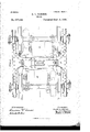
In the accompanying drawings, Figure lis a plan View. Fig. 2 is a side view. Fig. Sis a section 011 the line 3 3, Fig. l; and Fig. 4 is an end view.
A A are the side frames of the truck, each side frame, in the present instance, being composed of two plates a, a., secured together and to distance-pieces by rivets or bolts.
The pedestals a for the j ournal-boxes C are, in the present instance, made in the manner described and claimed in the application for pat-ent filed by George Westinghouse, J r., one side of each pedestal being rigidly attached to the side frame of the truck, while the other side of the pedestal is movable, so that it can swing to allow for the ready removal of the axle and its box from the truck.
On the axle C are the wheels c c.
Extending from one frame A to the other is a top plate D, made in one piece, in the present instance, and reduced in width at the center, but extended at each end, these extensions being secured to the frames A by rivets or bolts.
In order to stien the .truck land make it perfectly rigid, I secure to each edge of the plate D angle-plates D', curved at each end to conform to the shape of the top plate D. The upper iange d of each angle-plate rests upon the top plate D, and the deep depending flange CZ' is secured to transverse plates E E, forming a box for the bolster F, which has an open bottom, so that the bolsterand its springs can be removed from the bottom of the truck.-
Serial No. 583,936. (No model.)
The top plate D has a central opening and side openings for the passage, respectively, of the center plate e and the side bearingblocks e.
The swinging plate G carries the springs g g, one set at each end, and is suspended by links g from studs f, secured to the plates E. The springsggsupport the bolsterF. Openings are formed in the side frames A opposite the springs, so that access may be had to them and to the bolster.
I have shown brake mechanism in Figs. 1 and 2, although this mechanism forms no part of my present invention, but is shown simply to illustrate the method of applying the brakes to this form of truck, and I have also shown in Fig. 2 the motors M M, which are hung to each axle and suspended from the truck.
It will be seen by the above description that my invention is especially applicable to electric-locomotive trucks where the space between the center box or beam of the truck and the axles has to be entirely free for the reception of the motors, and by making the truck with simply a single center beam composed of the two angle-plates curved at each end and the top plate and side plates I make a truck which is rigid in every respect and will readily support the weight without encroaching upon the room reserved for the motors.
I claim as my invention- 1. The combination in a truck, of the side frames, the transom, and angle-plates curved at each end, one flange of each angle-plate extending on top of the side plates and transom, the other flan ge extending down the side of the transom and side plates, substantially as described.
2. The combination of the side frames of a truck having pedestals therein, a top plate extending from one side frame to the other narrow at the center and wide at each end where it is secured to Ithe side frames, an
angle-plate on each edge of the said plates,A
one flange of the angle-plate being secured to the top plate and the other flange extending downward, substantially as described.`
3. The combination of the side frames, pedestals therein, a top plate extending from one frame to the other, vertical plates under name to this specification in the presence of the top plate and angle-plates, one ange of tWo subscribing Witnesses. each angle-plate being secured to the top plate and to the side frames, the otliei1 flange i DAVID L. BARNES. 5 being secured to the vertical plates and to Vitnesses:
the side frames, substantially as described. JAMES Gr. KEYS,
In testimony Wheieof I have signed my HENRY I-IOWSON.
Publications (1)
| Publication Number | Publication Date |
|---|---|
| US567444A true US567444A (en) | 1896-09-08 |
Family
ID=2636151
Family Applications (1)
| Application Number | Title | Priority Date | Filing Date |
|---|---|---|---|
| US567444D Expired - Lifetime US567444A (en) | Truck |
Country Status (1)
| Country | Link |
|---|---|
| US (1) | US567444A (en) |
-
0
- US US567444D patent/US567444A/en not_active Expired - Lifetime
Similar Documents
| Publication | Publication Date | Title |
|---|---|---|
| US623463A (en) | Truck | |
| US620911A (en) | Car-truck side frame | |
| US708994A (en) | Car-truck. | |
| US598074A (en) | Car-truck | |
| US574983A (en) | Car-truck frame | |
| US975093A (en) | Side frame. | |
| US946293A (en) | Car-truck. | |
| US577236A (en) | Car-truck frame | |
| US2470237A (en) | Side frame and brake support structure | |
| US567579A (en) | Car-truck frame | |
| US505152A (en) | Truck-frame | |
| US580534A (en) | richards | |
| US598449A (en) | Railway-car truck | |
| US737810A (en) | Constructing or forming car-trucks. | |
| US1039404A (en) | Car-truck. | |
| US798776A (en) | Car-truck. | |
| US636484A (en) | Car-truck. | |
| US553103A (en) | Freight-car truck | |
| US567472A (en) | Truck | |
| US431543A (en) | barnes | |
| US495338A (en) | Car-truck | |
| US1091107A (en) | Car-truck. | |
| US1015152A (en) | Truck. | |
| US2297748A (en) | Side frame | |
| US1068668A (en) | Truck side frame. |