US5669357A - Cylinder-selective injection system - Google Patents
Cylinder-selective injection system Download PDFInfo
- Publication number
- US5669357A US5669357A US08/636,710 US63671096A US5669357A US 5669357 A US5669357 A US 5669357A US 63671096 A US63671096 A US 63671096A US 5669357 A US5669357 A US 5669357A
- Authority
- US
- United States
- Prior art keywords
- fuel
- added
- cylinder
- notching
- sub
- Prior art date
- Legal status (The legal status is an assumption and is not a legal conclusion. Google has not performed a legal analysis and makes no representation as to the accuracy of the status listed.)
- Expired - Fee Related
Links
- 238000002347 injection Methods 0.000 title claims abstract description 71
- 239000007924 injection Substances 0.000 title claims abstract description 71
- 230000001629 suppression Effects 0.000 claims abstract description 36
- 230000001419 dependent effect Effects 0.000 claims abstract description 16
- 238000002485 combustion reaction Methods 0.000 claims abstract description 5
- 239000000446 fuel Substances 0.000 claims description 68
- 238000000034 method Methods 0.000 claims description 7
- 230000001186 cumulative effect Effects 0.000 claims description 4
- 230000000694 effects Effects 0.000 claims 1
- 238000010586 diagram Methods 0.000 description 13
- 238000012937 correction Methods 0.000 description 3
- 238000001816 cooling Methods 0.000 description 1
- 230000003247 decreasing effect Effects 0.000 description 1
- 239000003344 environmental pollutant Substances 0.000 description 1
- 231100000719 pollutant Toxicity 0.000 description 1
- 239000000243 solution Substances 0.000 description 1
Images


Classifications
-
- F—MECHANICAL ENGINEERING; LIGHTING; HEATING; WEAPONS; BLASTING
- F02—COMBUSTION ENGINES; HOT-GAS OR COMBUSTION-PRODUCT ENGINE PLANTS
- F02D—CONTROLLING COMBUSTION ENGINES
- F02D41/00—Electrical control of supply of combustible mixture or its constituents
- F02D41/02—Circuit arrangements for generating control signals
- F02D41/04—Introducing corrections for particular operating conditions
- F02D41/12—Introducing corrections for particular operating conditions for deceleration
- F02D41/123—Introducing corrections for particular operating conditions for deceleration the fuel injection being cut-off
- F02D41/126—Introducing corrections for particular operating conditions for deceleration the fuel injection being cut-off transitional corrections at the end of the cut-off period
-
- F—MECHANICAL ENGINEERING; LIGHTING; HEATING; WEAPONS; BLASTING
- F02—COMBUSTION ENGINES; HOT-GAS OR COMBUSTION-PRODUCT ENGINE PLANTS
- F02D—CONTROLLING COMBUSTION ENGINES
- F02D41/00—Electrical control of supply of combustible mixture or its constituents
- F02D41/008—Controlling each cylinder individually
- F02D41/0087—Selective cylinder activation, i.e. partial cylinder operation
-
- F—MECHANICAL ENGINEERING; LIGHTING; HEATING; WEAPONS; BLASTING
- F02—COMBUSTION ENGINES; HOT-GAS OR COMBUSTION-PRODUCT ENGINE PLANTS
- F02D—CONTROLLING COMBUSTION ENGINES
- F02D2250/00—Engine control related to specific problems or objectives
- F02D2250/18—Control of the engine output torque
- F02D2250/21—Control of the engine output torque during a transition between engine operation modes or states
Definitions
- the present invention relates to a fuel-injection system and in particular to a cylinder-selective injection system having an alternating pattern.
- German Patent Application No. DE 36 23 040 describes a cylinder-selective injection system, where the fuel supply is cut off during deceleration, the number of cylinders to be switched off being specified. An alternating pattern is provided specifying those cylinders which are not supplied with fuel, to prevent individual cylinders from cooling off too drastically.
- an object of the present invention is to introduce an optimal solution for this operating state.
- the present invention relates to a mixture-compressing internal combustion engine having cylinder-selective injection.
- a basic idea underlying the present invention is a cylinder-selective injection suppression, as well as a cylinder-specific restoring added fuel quantity for traction control, deceleration fuel cutoff, and rotational-frequency or speed limitation.
- the initial value of the added fuel quantity when the fuel supply is restored depends on the number of suppressed injections for the cylinder in question; and gradual return to zero of the added fuel quantity depends on the number of injections of the cylinder that have taken place after completion of the suppression operation.
- the cylinder-selective injection system according to the present invention makes it possible to attain an excellent ride comfort while simultaneously achieving good exhaust emission specifications.
- FIG. 1 shows pulse diagrams of injections that are taking place and those that are suppressed, as well as the time characteristic of the added quantity factor.
- FIG. 2 shows a flow chart for calculating the injection period for an individual cylinder according to the present invention.
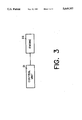
- FIG. 3 shows a block diagram of the apparatus according to the present invention.
- FIG. 1 the cylinder-selective injections of the four injection valves EV1 through EV4 are depicted with cylinder-specific suppressions (shown with a dotted line).
- the diagrams b1 through b4 in FIG. 1 show the characteristic curves of the cylinder-specific added quantities (FWE1-4) in dependence upon the number of injections that have occurred since the most recent suppression.
- FWE1 added fuel quantity
- diagram b1 for the cylinder 1 is notched up to larger values, beginning with the first suppression.
- the maximum value of the added fuel quantity (FWE1) tends toward a limiting value FWEMax.
- the value of the added fuel quantity is taken away with every injection, until this added fuel quantity has been taken away completely after a few injections.
- diagram a2 depicts a pattern with an alternating injection and suppression. One can discern that a certain added fuel quantity is made available with each missing injection, and that the added fuel quantity is taken away at the beginning of each injection.
- diagram a3 depicts a comparable pattern, one injection following after two suppressions.
- diagrams a4 and b4 show a pattern where two injection pulses follow a suppression.
- diagrams b1-b4 Discernible in all the diagrams according to FIG. 1, diagrams b1-b4 is a large initial increase in the desired added fuel quantity that becomes effective later on, and a withdrawal of the increase in this added fuel quantity with each additional suppressed cylinder. If an injection again takes place following the suppression, then the prevailing added fuel quantity is also reduced with a decreasing tendency.
- FIG. 2 shows an injection of suppression cycle for cylinder 1.
- FIG. 2 there is depicted the flow chart for calculating the period of the injection signal and its outputting to an individual injection valve, given a cylinder-selective restoring added fuel quantity. Due to the cylinder-selective injection-quantity control, the program flow described in the following is required for each cylinder.
- FIG. 2 shows the following steps:
- step 10 An initialization is denoted by step 10.
- step 11 a restoring added fuel quantity is set to the value 1 in accordance with the formula:
- step 12 it is determined whether the arc of crankshaft rotation has been reached for calculating the injection time of the cylinder. If the proper crankshaft rotation has been reached, then the injection period, as well as the start of injection angle for the next injection are calculated in the step 13 in accordance with the formula:
- n speed
- Step 13 is followed by step 14 where it is determined whether the start-of-injection angle gamma KW -- 1 has been reached.
- step 17 for calculating the added fuel quantity (FWE1) in accordance with the formula:
- ZWEAUF the added quantity notching-up rate
- TA the period of time between two regular injection-time outputs. Any desired speed-dependent value can be reached for TauAUF by selecting a speed-dependent value for ZWEAUF.
- step 19 this signifies a start of the injection with the injection time calculated in step 13.
- the added fuel quantity to be notched-down is determined according to the following formula:
- this formula means that after the injection for one cylinder i is restored, the added fuel quantity is notched-down according to the formula:
- k the number of injections after suppression of the cylinder i in question
- ZWEAB the added-quantity notching-down rate
- fwe -- i (0) the last notching-up value to be reached fwe -- i (a).
- TA the period of time between two regular injection-time outputs.
- an added-quantity calculation is performed, which is dependent upon the number of suppressed injection pulses for the special cylinder, or rather upon the number of injection pulses that have followed after at least one suppression.
- the added fuel quantity can thereby have a multiplicative or cumulative effect on the load signal t1 as the quotient of mass rate of air flow and speed.
- control time constant is zero, i.e., only the first injection pulse comprises an added fuel quantity after the suppression.
- FIG. 3 a block diagram of the apparatus according to the present invention shows the control unit 21 connected to the engine block 22.
- the control unit 21 controls fuel injection to the individual cylinders of the engine block 22, performing the method steps previously outlined.
- the principal advantage of the cylinder-selective injection system according to the present invention is that it makes it possible to guarantee combustion after a desired number of cylinder-selective suppressions. Finally, a desired lambda characteristic is attained in the best possible way for each individual cylinder, even after the suppressions have taken place.
Landscapes
- Engineering & Computer Science (AREA)
- Chemical & Material Sciences (AREA)
- Combustion & Propulsion (AREA)
- Mechanical Engineering (AREA)
- General Engineering & Computer Science (AREA)
- Electrical Control Of Air Or Fuel Supplied To Internal-Combustion Engine (AREA)
Abstract
In a cylinder-selective injection system for an internal combustion engine, there are cylinder-selective injection suppressions. Subsequent to the suppressions, restoring added quantities specific to an individual cylinder are generated, whose initial value is dependent upon the number of suppressed injections for the cylinder in question, and whose notching-down to zero is dependent upon the number of injections of the cylinder that have taken place after completion of the suppression.
Description
This application is a continuation of application Ser. No. 08/297,727, filed on Aug. 29, 1994.
The present invention relates to a fuel-injection system and in particular to a cylinder-selective injection system having an alternating pattern.
German Patent Application No. DE 36 23 040 describes a cylinder-selective injection system, where the fuel supply is cut off during deceleration, the number of cylinders to be switched off being specified. An alternating pattern is provided specifying those cylinders which are not supplied with fuel, to prevent individual cylinders from cooling off too drastically.
SAE Technical Paper No. 920641, entitled Traction Control (ASR) Using Fuel-Injection Suppression--A Cost Effective Method Of Engine-Torque Control, depicts a special pattern of active cylinders in FIG. 6, and the caption reads, Torque Reduction Stages with Alternating Fuel-Injection Suppression. At page 40 is described corrections to be made when restoring the fuel supply, so that the wall film may be rapidly built up again in the air intake tube.
It turns out that, in view of pollutant characteristics and ride comfort, considerable efforts must be made with respect to the restoring of the fuel supply. Therefore, an object of the present invention is to introduce an optimal solution for this operating state.
The present invention relates to a mixture-compressing internal combustion engine having cylinder-selective injection. A basic idea underlying the present invention is a cylinder-selective injection suppression, as well as a cylinder-specific restoring added fuel quantity for traction control, deceleration fuel cutoff, and rotational-frequency or speed limitation. The initial value of the added fuel quantity when the fuel supply is restored depends on the number of suppressed injections for the cylinder in question; and gradual return to zero of the added fuel quantity depends on the number of injections of the cylinder that have taken place after completion of the suppression operation.
As far as restoring the fuel quantity is concerned, the cylinder-selective injection system according to the present invention makes it possible to attain an excellent ride comfort while simultaneously achieving good exhaust emission specifications.
FIG. 1 shows pulse diagrams of injections that are taking place and those that are suppressed, as well as the time characteristic of the added quantity factor.
FIG. 2 shows a flow chart for calculating the injection period for an individual cylinder according to the present invention.
FIG. 3 shows a block diagram of the apparatus according to the present invention.
Referring to FIG. 1, the cylinder-selective injections of the four injection valves EV1 through EV4 are depicted with cylinder-specific suppressions (shown with a dotted line). The diagrams b1 through b4 in FIG. 1 show the characteristic curves of the cylinder-specific added quantities (FWE1-4) in dependence upon the number of injections that have occurred since the most recent suppression. One can discern that the added fuel quantity (FWE1) apparent in FIG. 1, diagram b1 for the cylinder 1 is notched up to larger values, beginning with the first suppression. The maximum value of the added fuel quantity (FWE1) tends toward a limiting value FWEMax. At the end of the suppressions, i.e., when the injections are restored, the value of the added fuel quantity is taken away with every injection, until this added fuel quantity has been taken away completely after a few injections.
In conjunction with diagram b2, diagram a2 depicts a pattern with an alternating injection and suppression. One can discern that a certain added fuel quantity is made available with each missing injection, and that the added fuel quantity is taken away at the beginning of each injection.
In conjunction with diagram b3, diagram a3 depicts a comparable pattern, one injection following after two suppressions.
Finally, diagrams a4 and b4 show a pattern where two injection pulses follow a suppression.
Discernible in all the diagrams according to FIG. 1, diagrams b1-b4 is a large initial increase in the desired added fuel quantity that becomes effective later on, and a withdrawal of the increase in this added fuel quantity with each additional suppressed cylinder. If an injection again takes place following the suppression, then the prevailing added fuel quantity is also reduced with a decreasing tendency.
A possibility for realizing the curve shapes of FIG. 1, diagrams b1-b4 in terms of software is depicted in the flow chart of FIG. 2 which shows an injection of suppression cycle for cylinder 1.
Referring now to FIG. 2, there is depicted the flow chart for calculating the period of the injection signal and its outputting to an individual injection valve, given a cylinder-selective restoring added fuel quantity. Due to the cylinder-selective injection-quantity control, the program flow described in the following is required for each cylinder.
FIG. 2 shows the following steps:
An initialization is denoted by step 10. In step 11, a restoring added fuel quantity is set to the value 1 in accordance with the formula:
fwe.sub.-- 1=1.
In step 12, it is determined whether the arc of crankshaft rotation has been reached for calculating the injection time of the cylinder. If the proper crankshaft rotation has been reached, then the injection period, as well as the start of injection angle for the next injection are calculated in the step 13 in accordance with the formula:
ti.sub.-- 1=t1*πFi*fwe.sub.-- 1+tvub
gamma KW.sub.-- 1=f(n, ti.sub.-- 1, wee),
in which case,
πFi=the product of the correction factors;
tvub=battery-voltage correction;
n=speed; and
wee=angle for the end of injection.
fwe.sub.-- 1=fwe.sub.-- 1+(FWEMX-fwe.sub.-- 1)*ZWEAUF
or generally expressed as:
fwe.sub.-- i(a)=fwe.sub.-- i(a-1)+ FWEMX-fwe.sub.-- i(a-1)!*ZWEAUF,
in which case,
a=the number of suppressions of the cylinder i in question;
FWEMX=maximum value of the added fuel quantity;
ZWEAUF=the added quantity notching-up rate; and
fwe-- i (0)=1, or
=the last notching-down (gradual shut-off) value fwe-- i (k) to be reached, in the case that a notching-down to 1 was not quite completed.
The result of the injection-synchronous calculation, given a constant ZWEAUF, is that the notching-up time constant TauAUF is inversely proportional to the speed, as the following formula to be derived from FIG. 1 shows:
TauAUF=TA/ZWEAUF,
in which case, TA=the period of time between two regular injection-time outputs. Any desired speed-dependent value can be reached for TauAUF by selecting a speed-dependent value for ZWEAUF.
If the query in step 15 has not resulted in any set suppression bit, then, according to step 19, this signifies a start of the injection with the injection time calculated in step 13. For the subsequent injection, the added fuel quantity to be notched-down is determined according to the following formula:
fwe.sub.-- 1=fwe.sub.-- 1+(1-fwe.sub.-- 1)* ZWEAB
Expressed generally, this formula means that after the injection for one cylinder i is restored, the added fuel quantity is notched-down according to the formula:
fwe.sub.-- i(k)=fwe.sub.-- i(k-1)+ 1-fwe.sub.-- i(k-1)!*ZWEAB,
in which case,
k=the number of injections after suppression of the cylinder i in question;
ZWEAB=the added-quantity notching-down rate; and
fwe-- i (0)=the last notching-up value to be reached fwe-- i (a).
Analogously to TauAUF, the statements on speed dependency and the following formula apply for the notching-down time constant TauAB:
TauAB=TA/ZWEAB,
in which case, TA=the period of time between two regular injection-time outputs.
Both calculation steps 17 and 20 lead back to step 12.
The following points are of fundamental importance to the invention:
For each cylinder, an added-quantity calculation is performed, which is dependent upon the number of suppressed injection pulses for the special cylinder, or rather upon the number of injection pulses that have followed after at least one suppression.
The added fuel quantity can thereby have a multiplicative or cumulative effect on the load signal t1 as the quotient of mass rate of air flow and speed.
For the notching-up of a cumulative added fuel quantity to be calculated at the start of suppression of the injections for a cylinder i, the following formula applies (in comparison to the above-mentioned formulae, "f" is replaced by "ad"):
adwe.sub.-- i(a)=adwe.sub.-- i(a-1)+ ADWEMX-adwe.sub.-- i(a-1)!*ZWEAUF
For the notching-down, the following formula applies:
adwe.sub.-- i(k)=adwe.sub.-- i(k-1)+ 1-adwe.sub.-- i(k-1)!*ZWEAB
Changes in the above-mentioned exemplified embodiment for the added-value calculation are conceivable in so far as the initial added fuel quantity is not dependent upon the number of suppressions, but rather is fixed. In all cases, however, the maximum added fuel quantity (in this case FWEMX) is made dependent upon operating parameters for the engine, such as speed, load, or engine temperature. In the same way, the notching-up and notching-down time constants (ZWEAUF, ZWEAB) can be made dependent on such operating parameters for the engine.
In a simple variation, the control time constant (engine-timing constant) is zero, i.e., only the first injection pulse comprises an added fuel quantity after the suppression.
In FIG. 3, a block diagram of the apparatus according to the present invention shows the control unit 21 connected to the engine block 22. The control unit 21 controls fuel injection to the individual cylinders of the engine block 22, performing the method steps previously outlined.
The principal advantage of the cylinder-selective injection system according to the present invention is that it makes it possible to guarantee combustion after a desired number of cylinder-selective suppressions. Finally, a desired lambda characteristic is attained in the best possible way for each individual cylinder, even after the suppressions have taken place.
Claims (16)
1. An apparatus for controlling a cylinder-selective fuel injection system for an internal combustion engine having cylinder-selective fuel injection suppression for providing a reduction in drive torque to effect at least one of traction control, deceleration fuel cutoff, and rotational speed limitation, comprising:
a control unit coupled to the fuel injection system, the control unit performing the steps of:
determining an added fuel quantity to be fed to each cylinder of the engine upon restoration of fuel injection to the respective engine cylinder;
initializing the added fuel quantity for each engine cylinder based upon a number of suppressed fuel injections for the respective engine cylinder;
decrementing the added fuel quantity for each engine cylinder to zero based upon a number of fuel injections to the respective engine cylinder taking place after the number of suppressed fuel injections; and
applying the added fuel quantity for each engine cylinder to the fuel injection system so that the fuel injection system injects a fuel injection quantity including the added fuel quantity into each respective engine cylinder.
2. The apparatus according to claim 1, further comprising a plurality of restoring added fuel quantities, and a plurality of gradual return to zeros for respective engine cylinders.
3. The apparatus according to claim 1, wherein the at least one restoring added fuel quantity notches-up according to the formula:
fwe.sub.-- i(a)=fwe.sub.-- i(a-1)+ FWEMX-fwe.sub.-- i(a-1)!*ZWEAUF,
wherein:
a=the number of suppressed injections for the respective engine cylinder;
FWEMX=a maximum value of the at least one restoring added quantity;
ZWEAUF=an added-quantity notching-up rate; and
fwe-- i (0)=1, or
=a last notching-down value to be reached when a notching-down to 1 is not completed.
4. The apparatus according to claim 3, wherein a notching-up time constant, TauAUF, inversely proportional to speed is defined according to the formula:
TauAUF=TA/ZWEAUF,
wherein TA=a period of time between two injection-time outputs.
5. The apparatus according to claim 1, wherein the at least one restoring added fuel quantity notches-down according to the formula:
fwe.sub.-- i(k)=fwe.sub.-- i(k-1)+ 1-fwe.sub.-- i(k-1)!*ZWEAB,
wherein:
k=the number of injections to the respective engine cylinder taking place after a suppressed injection;
ZWEAB=an added-quantity notching-down rate; and
fwe-- i(0)=a last notching-up value to be reached.
6. The apparatus according to claim 5, wherein a notching-down time constant, TauAB, inversely proportional to speed is defined according to the formula:
TauAB=TA/ZWEAB,
wherein TA=a period of time between two injection-time outputs.
7. The apparatus according to claim 3, wherein at least one cumulative restoring added fuel quantity notches-up according to the formula:
adwe.sub.-- i(a)=adwe.sub.-- i(a-1)+ ADWEMX-adwe.sub.-- i(a-1)!*ZWEAUF.
8. The apparatus according to claim 5, wherein at least one cumulative restoring added fuel quantity notches-down according to the formula:
adwe.sub.-- i(k)=adwe.sub.-- i(k-1)+ 1-adwe.sub.-- i(k-1)!*ZWEAB.
9. The apparatus according to claim 3, wherein the maximum value of the at least one restoring added fuel quantity is dependent upon at least one predetermined engine operating parameter.
10. The apparatus according to claim 3, wherein the added-quantity notching-up rate is dependent upon at least one predetermined engine operating parameter.
11. The apparatus according to claim 5, wherein the added-quantity notching-down rate is dependent upon at least one predetermined engine operating parameter.
12. A method for controlling a cylinder-selective fuel injection system for an internal combustion engine having cylinder-selective fuel injection suppression for providing a reduction in drive torque by providing at least one of traction control, deceleration fuel cutoff, and rotational speed limitation, comprising the steps of:
(a) calculating an injection time and angle for a next fuel injection or fuel suppression for the engine cylinder;
b) checking a state of a suppression bit;
c) calculating a value for a restoring added fuel quantity, the value being dependent upon a number of prior fuel suppressions and a notching-up rate if the suppression bit is set, and being dependent upon a number of fuel injections and a notching-down rate if the suppression bit is not set; and
d) performing the next fuel injection or fuel suppression by injecting a fuel injection quantity including the restoring added fuel quantity into the engine cylinder if the suppression bit is not set, and by refraining from injecting fuel if the suppression bit is set.
13. The method according to claim 12, wherein a plurality of restoring added fuel quantities are calculated and injected.
14. The method according to claim 12, wherein the restoring added fuel quantity has a maximum value dependent upon at least one predetermined engine operating parameter.
15. The method according to claim 12, wherein the notching-up rate is dependent upon at least one predetermined engine operating parameter.
16. The method according to claim 12, wherein the notching-down rate is dependent upon at least one predetermined engine operating parameter.
Priority Applications (1)
| Application Number | Priority Date | Filing Date | Title |
|---|---|---|---|
| US08/636,710 US5669357A (en) | 1993-08-27 | 1996-04-23 | Cylinder-selective injection system |
Applications Claiming Priority (4)
| Application Number | Priority Date | Filing Date | Title |
|---|---|---|---|
| DE4328835.9 | 1993-08-27 | ||
| DE4328835A DE4328835C2 (en) | 1993-08-27 | 1993-08-27 | Cylinder-selective injection system |
| US29772794A | 1994-08-29 | 1994-08-29 | |
| US08/636,710 US5669357A (en) | 1993-08-27 | 1996-04-23 | Cylinder-selective injection system |
Related Parent Applications (1)
| Application Number | Title | Priority Date | Filing Date |
|---|---|---|---|
| US29772794A Continuation | 1993-08-27 | 1994-08-29 |
Publications (1)
| Publication Number | Publication Date |
|---|---|
| US5669357A true US5669357A (en) | 1997-09-23 |
Family
ID=6496157
Family Applications (1)
| Application Number | Title | Priority Date | Filing Date |
|---|---|---|---|
| US08/636,710 Expired - Fee Related US5669357A (en) | 1993-08-27 | 1996-04-23 | Cylinder-selective injection system |
Country Status (4)
| Country | Link |
|---|---|
| US (1) | US5669357A (en) |
| JP (1) | JPH07150997A (en) |
| DE (1) | DE4328835C2 (en) |
| GB (1) | GB2282675B (en) |
Cited By (21)
| Publication number | Priority date | Publication date | Assignee | Title |
|---|---|---|---|---|
| US5839409A (en) * | 1996-02-06 | 1998-11-24 | Robert Bosch Gmbh | Process for finding an additional quantity of fuel to be injected during reinjection in an internal combustion engine |
| US6273208B1 (en) * | 1998-10-15 | 2001-08-14 | Darrel R. Sand | Variable displacement vehicle engine and solid torque tube drive train |
| US6754578B1 (en) | 2003-03-27 | 2004-06-22 | Ford Global Technologies, Llc | Computer instructions for control of multi-path exhaust system in an engine |
| US20050065709A1 (en) * | 2003-09-23 | 2005-03-24 | Cullen Michael J. | System and method to control cylinder activation and deactivation |
| US20050166900A1 (en) * | 2004-01-29 | 2005-08-04 | Gang Song | Engine control to compensate for fueling dynamics |
| US20050172933A1 (en) * | 2004-02-09 | 2005-08-11 | Honda Motor Co., Ltd. | Fuel injection control system |
| US20100006065A1 (en) * | 2008-07-11 | 2010-01-14 | Tula Technology, Inc. | Internal combustion engine control for improved fuel efficiency |
| US20100010724A1 (en) * | 2008-07-11 | 2010-01-14 | Tula Technology, Inc. | Internal combustion engine control for improved fuel efficiency |
| US20110048372A1 (en) * | 2008-07-11 | 2011-03-03 | Dibble Robert W | System and Methods for Stoichiometric Compression Ignition Engine Control |
| US20110208405A1 (en) * | 2008-07-11 | 2011-08-25 | Tula Technology, Inc. | Internal combustion engine control for improved fuel efficiency |
| US8402942B2 (en) | 2008-07-11 | 2013-03-26 | Tula Technology, Inc. | System and methods for improving efficiency in internal combustion engines |
| US8511281B2 (en) | 2009-07-10 | 2013-08-20 | Tula Technology, Inc. | Skip fire engine control |
| US8701628B2 (en) | 2008-07-11 | 2014-04-22 | Tula Technology, Inc. | Internal combustion engine control for improved fuel efficiency |
| US8869773B2 (en) | 2010-12-01 | 2014-10-28 | Tula Technology, Inc. | Skip fire internal combustion engine control |
| US9020735B2 (en) | 2008-07-11 | 2015-04-28 | Tula Technology, Inc. | Skip fire internal combustion engine control |
| US9328672B2 (en) | 2012-07-31 | 2016-05-03 | Tula Technology, Inc. | Engine braking controller |
| US9664130B2 (en) | 2008-07-11 | 2017-05-30 | Tula Technology, Inc. | Using cylinder firing history for combustion control in a skip fire engine |
| US9790867B2 (en) | 2012-07-31 | 2017-10-17 | Tula Technology, Inc. | Deceleration cylinder cut-off |
| US10167799B2 (en) | 2012-07-31 | 2019-01-01 | Tula Technology, Inc. | Deceleration cylinder cut-off in a hybrid vehicle |
| US10408140B2 (en) | 2012-07-31 | 2019-09-10 | Tula Technology, Inc. | Engine control in fuel and/or cylinder cut off modes based on intake manifold pressure |
| US11549455B2 (en) | 2019-04-08 | 2023-01-10 | Tula Technology, Inc. | Skip cylinder compression braking |
Families Citing this family (8)
| Publication number | Priority date | Publication date | Assignee | Title |
|---|---|---|---|---|
| WO1996000347A1 (en) * | 1994-06-24 | 1996-01-04 | Siemens Aktiengesellschaft | Method of controlling the fuel supply to an internal-combustion engine with a selective cylinder cut-off capability |
| DE19508643B4 (en) * | 1995-03-10 | 2004-09-23 | Robert Bosch Gmbh | Method for determining the fuel injection quantity when a hidden cylinder is reinserted |
| DE19615828B4 (en) * | 1996-04-20 | 2007-04-26 | Robert Bosch Gmbh | Method for controlling the fuel cut of an internal combustion engine |
| JP3709652B2 (en) * | 1997-05-13 | 2005-10-26 | 日産自動車株式会社 | Vehicle driving force control device |
| JP3550951B2 (en) * | 1997-06-20 | 2004-08-04 | 日産自動車株式会社 | Driving force control device for vehicles |
| DE60209614T2 (en) * | 2002-11-11 | 2006-08-03 | Ford Global Technologies, LLC, Dearborn | Method for controlling an internal combustion engine |
| US9429081B2 (en) | 2014-04-25 | 2016-08-30 | GM Global Technology Operations LLC | Cylinder re-activation fueling control systems and methods |
| JP6120019B2 (en) * | 2015-02-19 | 2017-04-26 | トヨタ自動車株式会社 | Control device for internal combustion engine |
Citations (10)
| Publication number | Priority date | Publication date | Assignee | Title |
|---|---|---|---|---|
| US4242991A (en) * | 1977-06-21 | 1981-01-06 | Robert Bosch Gmbh | Method and apparatus for adjusting fuel supply to an internal combustion engine |
| US4250853A (en) * | 1976-08-18 | 1981-02-17 | Nippondenso Co. Ltd. | Method and apparatus for controlling the fuel supply of an internal combustion engine |
| US5018595A (en) * | 1989-07-11 | 1991-05-28 | Nippondenso Co., Ltd. | Traction control system |
| US5025881A (en) * | 1989-07-25 | 1991-06-25 | General Motors Corporation | Vehicle traction control system with fuel control |
| US5119781A (en) * | 1991-02-28 | 1992-06-09 | General Motors Corporation | Control of engine fuel injection during transitional periods associated with deceleration fuel cut-off |
| US5136996A (en) * | 1990-05-22 | 1992-08-11 | Toyota Jidosha Kabushiki Kaisha | Ignition system and method for internal combustion engine |
| US5154151A (en) * | 1990-02-23 | 1992-10-13 | Lucas Industries Public Limited Company | Method and apparatus for controlling engine torque and wheel spin |
| US5168952A (en) * | 1987-06-11 | 1992-12-08 | Honda Giken Kogyo Kabushiki Kaisha | Driving wheel slip control system for vehicles |
| US5275143A (en) * | 1989-04-08 | 1994-01-04 | Robert Bosch Gmbh | Method for reducing the fuel supply for one engine cylinder |
| US5287279A (en) * | 1990-11-30 | 1994-02-15 | Mazda Motor Corporation | Engine output torque control system |
Family Cites Families (1)
| Publication number | Priority date | Publication date | Assignee | Title |
|---|---|---|---|---|
| DE3623040A1 (en) * | 1986-07-09 | 1988-01-14 | Bosch Gmbh Robert | Method of fuel injection |
-
1993
- 1993-08-27 DE DE4328835A patent/DE4328835C2/en not_active Expired - Fee Related
-
1994
- 1994-08-15 JP JP6191363A patent/JPH07150997A/en active Pending
- 1994-08-25 GB GB9417181A patent/GB2282675B/en not_active Expired - Fee Related
-
1996
- 1996-04-23 US US08/636,710 patent/US5669357A/en not_active Expired - Fee Related
Patent Citations (10)
| Publication number | Priority date | Publication date | Assignee | Title |
|---|---|---|---|---|
| US4250853A (en) * | 1976-08-18 | 1981-02-17 | Nippondenso Co. Ltd. | Method and apparatus for controlling the fuel supply of an internal combustion engine |
| US4242991A (en) * | 1977-06-21 | 1981-01-06 | Robert Bosch Gmbh | Method and apparatus for adjusting fuel supply to an internal combustion engine |
| US5168952A (en) * | 1987-06-11 | 1992-12-08 | Honda Giken Kogyo Kabushiki Kaisha | Driving wheel slip control system for vehicles |
| US5275143A (en) * | 1989-04-08 | 1994-01-04 | Robert Bosch Gmbh | Method for reducing the fuel supply for one engine cylinder |
| US5018595A (en) * | 1989-07-11 | 1991-05-28 | Nippondenso Co., Ltd. | Traction control system |
| US5025881A (en) * | 1989-07-25 | 1991-06-25 | General Motors Corporation | Vehicle traction control system with fuel control |
| US5154151A (en) * | 1990-02-23 | 1992-10-13 | Lucas Industries Public Limited Company | Method and apparatus for controlling engine torque and wheel spin |
| US5136996A (en) * | 1990-05-22 | 1992-08-11 | Toyota Jidosha Kabushiki Kaisha | Ignition system and method for internal combustion engine |
| US5287279A (en) * | 1990-11-30 | 1994-02-15 | Mazda Motor Corporation | Engine output torque control system |
| US5119781A (en) * | 1991-02-28 | 1992-06-09 | General Motors Corporation | Control of engine fuel injection during transitional periods associated with deceleration fuel cut-off |
Cited By (46)
| Publication number | Priority date | Publication date | Assignee | Title |
|---|---|---|---|---|
| US5839409A (en) * | 1996-02-06 | 1998-11-24 | Robert Bosch Gmbh | Process for finding an additional quantity of fuel to be injected during reinjection in an internal combustion engine |
| US6273208B1 (en) * | 1998-10-15 | 2001-08-14 | Darrel R. Sand | Variable displacement vehicle engine and solid torque tube drive train |
| US6754578B1 (en) | 2003-03-27 | 2004-06-22 | Ford Global Technologies, Llc | Computer instructions for control of multi-path exhaust system in an engine |
| US20040187484A1 (en) * | 2003-03-27 | 2004-09-30 | Bidner David Karl | Computer instructions for control of multi-path exhaust system in an engine |
| US6901327B2 (en) | 2003-03-27 | 2005-05-31 | Ford Global Technologies, Llc | Computer instructions for control of multi-path exhaust system in an engine |
| US20050065709A1 (en) * | 2003-09-23 | 2005-03-24 | Cullen Michael J. | System and method to control cylinder activation and deactivation |
| US7328686B2 (en) | 2003-09-23 | 2008-02-12 | Ford Global Technologies Llc | System and method to control cylinder activation and deactivation |
| US20050166900A1 (en) * | 2004-01-29 | 2005-08-04 | Gang Song | Engine control to compensate for fueling dynamics |
| US7111593B2 (en) * | 2004-01-29 | 2006-09-26 | Ford Global Technologies, Llc | Engine control to compensate for fueling dynamics |
| US20050172933A1 (en) * | 2004-02-09 | 2005-08-11 | Honda Motor Co., Ltd. | Fuel injection control system |
| US7140348B2 (en) * | 2004-02-09 | 2006-11-28 | Honda Motor Co., Ltd. | Fuel injection control system |
| US8131445B2 (en) | 2008-07-11 | 2012-03-06 | Tula Technology, Inc. | Internal combustion engine control for improved fuel efficiency |
| US8616181B2 (en) | 2008-07-11 | 2013-12-31 | Tula Technology, Inc. | Internal combustion engine control for improved fuel efficiency |
| US20100050986A1 (en) * | 2008-07-11 | 2010-03-04 | Tula Technology, Inc. | Internal combustion engine control for improved fuel efficiency |
| US20100050985A1 (en) * | 2008-07-11 | 2010-03-04 | Tula Technology, Inc. | Internal combustion engine control for improved fuel efficiency |
| US7849835B2 (en) | 2008-07-11 | 2010-12-14 | Tula Technology, Inc. | Internal combustion engine control for improved fuel efficiency |
| US7886715B2 (en) | 2008-07-11 | 2011-02-15 | Tula Technology, Inc. | Internal combustion engine control for improved fuel efficiency |
| US20110048372A1 (en) * | 2008-07-11 | 2011-03-03 | Dibble Robert W | System and Methods for Stoichiometric Compression Ignition Engine Control |
| US7954474B2 (en) | 2008-07-11 | 2011-06-07 | Tula Technology, Inc. | Internal combustion engine control for improved fuel efficiency |
| US20110208405A1 (en) * | 2008-07-11 | 2011-08-25 | Tula Technology, Inc. | Internal combustion engine control for improved fuel efficiency |
| US20110213541A1 (en) * | 2008-07-11 | 2011-09-01 | Tula Technology, Inc. | Internal combustion engine control for improved fuel efficiency |
| US8099224B2 (en) | 2008-07-11 | 2012-01-17 | Tula Technology, Inc. | Internal combustion engine control for improved fuel efficiency |
| US20100006065A1 (en) * | 2008-07-11 | 2010-01-14 | Tula Technology, Inc. | Internal combustion engine control for improved fuel efficiency |
| US8131447B2 (en) | 2008-07-11 | 2012-03-06 | Tula Technology, Inc. | Internal combustion engine control for improved fuel efficiency |
| US8336521B2 (en) | 2008-07-11 | 2012-12-25 | Tula Technology, Inc. | Internal combustion engine control for improved fuel efficiency |
| US8402942B2 (en) | 2008-07-11 | 2013-03-26 | Tula Technology, Inc. | System and methods for improving efficiency in internal combustion engines |
| US8499743B2 (en) | 2008-07-11 | 2013-08-06 | Tula Technology, Inc. | Skip fire engine control |
| US10273894B2 (en) | 2008-07-11 | 2019-04-30 | Tula Technology, Inc. | Internal combustion engine control for improved fuel efficiency |
| US20100010724A1 (en) * | 2008-07-11 | 2010-01-14 | Tula Technology, Inc. | Internal combustion engine control for improved fuel efficiency |
| US8646435B2 (en) | 2008-07-11 | 2014-02-11 | Tula Technology, Inc. | System and methods for stoichiometric compression ignition engine control |
| US9982611B2 (en) | 2008-07-11 | 2018-05-29 | Tula Technology, Inc. | Internal combustion engine control for improved fuel efficiency |
| US8701628B2 (en) | 2008-07-11 | 2014-04-22 | Tula Technology, Inc. | Internal combustion engine control for improved fuel efficiency |
| US9664130B2 (en) | 2008-07-11 | 2017-05-30 | Tula Technology, Inc. | Using cylinder firing history for combustion control in a skip fire engine |
| US9020735B2 (en) | 2008-07-11 | 2015-04-28 | Tula Technology, Inc. | Skip fire internal combustion engine control |
| US9086024B2 (en) | 2008-07-11 | 2015-07-21 | Tula Technology, Inc. | Internal combustion engine control for improved fuel efficiency |
| US9541050B2 (en) | 2008-07-11 | 2017-01-10 | Tula Technology, Inc. | Internal combustion engine control for improved fuel efficiency |
| US8651091B2 (en) | 2009-07-10 | 2014-02-18 | Tula Technology, Inc. | Skip fire engine control |
| US8511281B2 (en) | 2009-07-10 | 2013-08-20 | Tula Technology, Inc. | Skip fire engine control |
| US8869773B2 (en) | 2010-12-01 | 2014-10-28 | Tula Technology, Inc. | Skip fire internal combustion engine control |
| US9328672B2 (en) | 2012-07-31 | 2016-05-03 | Tula Technology, Inc. | Engine braking controller |
| US9790867B2 (en) | 2012-07-31 | 2017-10-17 | Tula Technology, Inc. | Deceleration cylinder cut-off |
| US10167799B2 (en) | 2012-07-31 | 2019-01-01 | Tula Technology, Inc. | Deceleration cylinder cut-off in a hybrid vehicle |
| US10408140B2 (en) | 2012-07-31 | 2019-09-10 | Tula Technology, Inc. | Engine control in fuel and/or cylinder cut off modes based on intake manifold pressure |
| US10900425B2 (en) | 2012-07-31 | 2021-01-26 | Tula Technology, Inc. | Engine diagnostics during cylinder cut off operation |
| US11352966B2 (en) | 2012-07-31 | 2022-06-07 | Tula Technology, Inc. | Deceleration cylinder cut-off |
| US11549455B2 (en) | 2019-04-08 | 2023-01-10 | Tula Technology, Inc. | Skip cylinder compression braking |
Also Published As
| Publication number | Publication date |
|---|---|
| DE4328835C2 (en) | 2002-09-05 |
| GB9417181D0 (en) | 1994-10-12 |
| DE4328835A1 (en) | 1995-03-02 |
| GB2282675A (en) | 1995-04-12 |
| GB2282675B (en) | 1997-09-24 |
| JPH07150997A (en) | 1995-06-13 |
Similar Documents
| Publication | Publication Date | Title |
|---|---|---|
| US5669357A (en) | Cylinder-selective injection system | |
| JP3146001B2 (en) | Method and apparatus for controlling an internal combustion engine | |
| US5746183A (en) | Method and system for controlling fuel delivery during transient engine conditions | |
| JP2877511B2 (en) | Method for adjusting the air amount and fuel amount of a multi-cylinder internal combustion engine | |
| JPH07166946A (en) | Method and equipment for controlling temperature of exhaust-valve in engine fuel cut-off mode | |
| US5884602A (en) | Process for suppressing torque jumps during operation of an internal combustion engine | |
| JP2008309036A (en) | Fuel estimation device | |
| JPS62178739A (en) | Electronically controlled fuel injection device | |
| US7383813B2 (en) | Method and device for controlling the transition between normal operation and overrun fuel cut-off operation of an Otto engine operated with direct fuel injection | |
| CN101238280A (en) | fuel injection control system | |
| US5497752A (en) | Device for controlling fuel injection of an internal combustion engine | |
| GB2351816A (en) | Controlling multi-phase fuel injection in an internal combustion engine | |
| US4640253A (en) | Electronic fuel injection control with variable injection timing | |
| EP0671556B1 (en) | A device for controlling fuel injection in an internal combustion engine | |
| JPS63285240A (en) | Fuel control device for internal combustion engine | |
| JP3651191B2 (en) | Fuel injection control device for internal combustion engine | |
| GB2193014A (en) | Fuel injection control | |
| US4562819A (en) | Method and apparatus for controlling fuel supply of an internal combustion engine | |
| KR940008273B1 (en) | Engine Fuel Control | |
| JP3975717B2 (en) | Fuel injection control system and fuel injection control method | |
| JPH1061467A (en) | Method for determining excess fuel quantity supplied to internal combustion engine in warm-up operation | |
| US5043901A (en) | Air-fuel ratio controller | |
| US6612297B2 (en) | Method of controlling an engine startup | |
| JP3968905B2 (en) | Engine fuel injection control device | |
| JPH0362894B2 (en) |
Legal Events
| Date | Code | Title | Description |
|---|---|---|---|
| FEPP | Fee payment procedure |
Free format text: PAYOR NUMBER ASSIGNED (ORIGINAL EVENT CODE: ASPN); ENTITY STATUS OF PATENT OWNER: LARGE ENTITY |
|
| FPAY | Fee payment |
Year of fee payment: 4 |
|
| REMI | Maintenance fee reminder mailed | ||
| LAPS | Lapse for failure to pay maintenance fees | ||
| STCH | Information on status: patent discontinuation |
Free format text: PATENT EXPIRED DUE TO NONPAYMENT OF MAINTENANCE FEES UNDER 37 CFR 1.362 |
|
| FP | Lapsed due to failure to pay maintenance fee |
Effective date: 20050923 |