US566756A - harris - Google Patents
harris Download PDFInfo
- Publication number
- US566756A US566756A US566756DA US566756A US 566756 A US566756 A US 566756A US 566756D A US566756D A US 566756DA US 566756 A US566756 A US 566756A
- Authority
- US
- United States
- Prior art keywords
- door
- casing
- bolts
- gas
- furnace
- Prior art date
- Legal status (The legal status is an assumption and is not a legal conclusion. Google has not performed a legal analysis and makes no representation as to the accuracy of the status listed.)
- Expired - Lifetime
Links
- 238000010276 construction Methods 0.000 description 4
- 239000011449 brick Substances 0.000 description 2
- 101100334009 Caenorhabditis elegans rib-2 gene Proteins 0.000 description 1
- 239000000463 material Substances 0.000 description 1
- 239000002184 metal Substances 0.000 description 1
Images
Classifications
-
- C—CHEMISTRY; METALLURGY
- C10—PETROLEUM, GAS OR COKE INDUSTRIES; TECHNICAL GASES CONTAINING CARBON MONOXIDE; FUELS; LUBRICANTS; PEAT
- C10B—DESTRUCTIVE DISTILLATION OF CARBONACEOUS MATERIALS FOR PRODUCTION OF GAS, COKE, TAR, OR SIMILAR MATERIALS
- C10B25/00—Doors or closures for coke ovens
- C10B25/20—Lids or closures for charging holes
- C10B25/24—Lids or closures for charging holes for ovens with horizontal chambers
Definitions
- My invention relates to doors for furnaces used in gas-making or in metallurgical operations, or for other purposes requiring a closefitting, gas-tight, and non-conducting door; and the objects of the invention are to so construct the door as to provide for a perfect seal without the use of packing-rings and so that the door and its seal-joint will withstand an intense heat and heavy back pressure and at the same time permit the seal to be released quickly and the door swung back out of the way, and yet be able to secure it again as readily.
- the invention consists in the features of construction and novel combinations of parts in a door for furnaces and gas-generators, as hereinafter more particularly described and claimed.
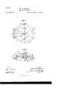
- Figure 1 is a plan of my improved furnace-door, partly broken away to show a portion of the door casing or frame and the slotted lugs thereon corresponding with similar lugs on the door for engagement with the bolts that secure the door when closed.
- Fig. 2 is a transverse section through the furnacedoor and its frame or casing.
- the numeral 1 designates a metal door frame or casing that may have any suitable form and be made of a proper diameter tofit accurately into the furnace-opening for which the door is intended.
- a flange or rib 2 On the periphery of the door-casing, intermediate its inner and outer edges, there may be formed a flange or rib 2, provided with a series of perforations 3 for passage of bolts or rivets employed to firmly secure the door frame or casing 1 to the furnace.
- the outer edge of the frame or casin g 1 is provided at suitable intervals with a series of laterallyprojecting lugs 4, having elongated openended slots 5 formed therein to correspond with a similar construction provided on the door 6, and thus afford a simple and convenient means for enabling the door to be securely bolted to its frame or casing after the door has been closed.
- the furnace-door 6 has on its inner side an inwardly-projecting flange 7, Fig. 2, forming a recess for reception of a refractory lining, (not shown,) which may consist of fire-brick or other suitable material.
- a refractory lining (not shown,) which may consist of fire-brick or other suitable material.
- the door 6 On its outer face the door 6 may be dished, as shown in Fig. 2, and its inner side may have a series of radially-disposed ribs 8 to impart strength to the door and assist also in supporting the refractory lining with which the door is to be provided.
- a clamping plate or disk 9 As a means for clamping the refractory or fire-brick door-lining in place, I have provided on the inner side of the door a clamping plate or disk 9, Fig. 2, with which are engaged two screw-bolts 10, that are passed through the door 6 at suitable points and secured on the outside by nuts 11, that can be rotated to tighten said bolts and draw the clamping-plate 9 tightly against the refractorylining to hold the same securelyin place.
- annular rim or shoulder 12 On the outside of the door-flange 7 and at the outer edge of the door is an annular rim or shoulder 12, which is adapted to fit closely onto the outer edge of the door-casing 1 when the door is closed, and in order to secure a close and tight fit the contacting surfaces of the casing 1 and rim or shoulder 12 may be accurately ground.
- lugs 13 At suitable intervals on the door rim or shoulder 12 are formed laterally-projecting lugs 13, corresponding with the similar lugs i on the door-casing 1, and like them provided with elongated open-ended slots 14: for the passage of bolts 15 to securely fasten the closed door.
- the bolts 15 are headed on their inner ends and their outer ends are provided with nuts 16, by which the bolts can be firmly tightened.
- the slots 5 of the door-casing 1 and the corresponding slots 14 of the door 6 are open-ended, so that the bolts 15 can be readily inserted sidewise.
- the door when unfastened, is to be swung open upon a hinge 17, provided at one side.
- the fixed portion of this hinge is mounted upon alaterally-extended portion of the doorcasing flange 2, and the movable portion is provided with a partly-curved arm 18, that is extended centrally to the outer side of the door.
- To the end of the hinge-arm 18 is attached an inwardly-projecting stud 19, that may be secured by having a flange or shoulder 20 thereon to bear against the inner side of the arm 18 and bya nut 21 on the outside.
- the stud 19 On its inner end the stud 19 carries a ball 22, Fig. 2,fitting into a hemispherical socket 23,formcd centrally on the outside of the furnace-door.
- ahemispherical socket-cap 24 is provided, and in the center of this socket-cap 24 is an opening 25, through which the stud 19 passes, and which is of sufficient area to permit the door 6 to have a little play through the ball-andsocket joint, by which it is thus connected to the hinge-arm.
- the socket-cap 24 is provided with suitable lugs for the passage of screwbolts 26 to engage similar lugs on the doorsocket 23 and thereby fasten the cap 24, so as to complete the ball-and-socket connection between the furnace-door and its hinge-support.
- This ball-and-socket connection between the door 6 and hinge-arm 18 will permit the door to have sufficient flexibility to yield to the straining of the bolts 15 when tightened by their nuts 16 in fastening the closed door firmly to its frame or casing, and thus the door, when closed, can be securely fastened or sealed and yet be readily and quickly opened when required.
- a door constructed as described will easily resist the intense heat of a gas-generator or metallurgical furnace.
- the seal-joint is perfectly gas-tight without requiring the use of packing-rings, and will readily withstand a very heavy back pressure.
- the door can be quickly unfastened and thrown open and the ball-and-socket hinge connection leaves it free to be drawn to the door seat or frame to form a close and tight joint therewith under the straining of the fastening-bolts.
- a door of this construction when closed and securely bolted, will be effectually sealed and made gas-tight against any escape of gas under a heavy back pressure, and thus the door is particularly adapted for use in the construction of a gas-generating apparatus.
- ⁇ Vhat I claim as my invention is The herein-described gas-tight door for gasgenerators or metallurgical furnaces, the said door having a ribbed and recessed inner side for reception of a refractory lining held in place by a clamping-plate and provided with a dished exterior surface having a ball-andsocket connection with a hinge arm fulcrumed on a door frame or casing to which the said door is adapted to be bolted when closed, whereby the escape of gas is prevented under back pressure within the furnace or generator, substantially as specified.
Landscapes
- Chemical & Material Sciences (AREA)
- Engineering & Computer Science (AREA)
- Materials Engineering (AREA)
- Oil, Petroleum & Natural Gas (AREA)
- Organic Chemistry (AREA)
- Furnace Housings, Linings, Walls, And Ceilings (AREA)
Description
(N0 Modeh) V W. H. HARRIS.
DOOR FOR FURNACES.
No. 566,756. Patented Sept. 1, 1896.
WITNESSES l/Vi/ENTOR UNITED STATES PATENT OFFICE.
WILLIAM; H. HARRIS, OF XVASHINGTON, DISTRICT OF COLUMBIA, ASSIGNOR TO WILLIAM A. MILLIKEN, OF SAME PLACE.
DOOR FOR FURNACES.
SPECIFICATION forming part of Letters Patent No. 566,? 56, dated September 1, 1896.
Application filed May 9, 1895. Serial No. 548,780. (No model.)
To all whom it may concern.-
Be it known that 1, WILLIAM H. HARRIS, a citizen of the United States, residing at'Washington city, District of Columbia, have invent-ed new and useful Improvements in Doors for Furnaces Used in Gas-Makin g or in Metallurgical Operations, of which the following is a specification.
My invention relates to doors for furnaces used in gas-making or in metallurgical operations, or for other purposes requiring a closefitting, gas-tight, and non-conducting door; and the objects of the invention are to so construct the door as to provide for a perfect seal without the use of packing-rings and so that the door and its seal-joint will withstand an intense heat and heavy back pressure and at the same time permit the seal to be released quickly and the door swung back out of the way, and yet be able to secure it again as readily.
The invention consists in the features of construction and novel combinations of parts in a door for furnaces and gas-generators, as hereinafter more particularly described and claimed.
In the annexed drawings, illustrating the invention, Figure 1 is a plan of my improved furnace-door, partly broken away to show a portion of the door casing or frame and the slotted lugs thereon corresponding with similar lugs on the door for engagement with the bolts that secure the door when closed. Fig. 2 is a transverse section through the furnacedoor and its frame or casing.
Referring to the drawings, the numeral 1 designates a metal door frame or casing that may have any suitable form and be made of a proper diameter tofit accurately into the furnace-opening for which the door is intended. On the periphery of the door-casing, intermediate its inner and outer edges, there may be formed a flange or rib 2, provided with a series of perforations 3 for passage of bolts or rivets employed to firmly secure the door frame or casing 1 to the furnace. The outer edge of the frame or casin g 1 is provided at suitable intervals with a series of laterallyprojecting lugs 4, having elongated openended slots 5 formed therein to correspond with a similar construction provided on the door 6, and thus afford a simple and convenient means for enabling the door to be securely bolted to its frame or casing after the door has been closed.
The furnace-door 6 has on its inner side an inwardly-projecting flange 7, Fig. 2, forming a recess for reception of a refractory lining, (not shown,) which may consist of fire-brick or other suitable material. On its outer face the door 6 may be dished, as shown in Fig. 2, and its inner side may have a series of radially-disposed ribs 8 to impart strength to the door and assist also in supporting the refractory lining with which the door is to be provided.
As a means for clamping the refractory or fire-brick door-lining in place, I have provided on the inner side of the door a clamping plate or disk 9, Fig. 2, with which are engaged two screw-bolts 10, that are passed through the door 6 at suitable points and secured on the outside by nuts 11, that can be rotated to tighten said bolts and draw the clamping-plate 9 tightly against the refractorylining to hold the same securelyin place.
On the outside of the door-flange 7 and at the outer edge of the door is an annular rim or shoulder 12, which is adapted to fit closely onto the outer edge of the door-casing 1 when the door is closed, and in order to secure a close and tight fit the contacting surfaces of the casing 1 and rim or shoulder 12 may be accurately ground.
At suitable intervals on the door rim or shoulder 12 are formed laterally-projecting lugs 13, corresponding with the similar lugs i on the door-casing 1, and like them provided with elongated open-ended slots 14: for the passage of bolts 15 to securely fasten the closed door. The bolts 15 are headed on their inner ends and their outer ends are provided with nuts 16, by which the bolts can be firmly tightened. At their outer ends the slots 5 of the door-casing 1 and the corresponding slots 14 of the door 6 are open-ended, so that the bolts 15 can be readily inserted sidewise. When it is desired to unfasten the furnacedoor, it is only necessary to loosen or remove the nuts 16, and the bolts 15 can then be knocked sidewise out of the slots 5 and 14c and thus permit the door to be opened. By this manner of fastening the door it will be securely sealed, and yet the fastenings may be readily and quickly removed whenever it is required to give access to the furnace.
The door, when unfastened, is to be swung open upon a hinge 17, provided at one side. The fixed portion of this hinge is mounted upon alaterally-extended portion of the doorcasing flange 2, and the movable portion is provided with a partly-curved arm 18, that is extended centrally to the outer side of the door. To the end of the hinge-arm 18 is attached an inwardly-projecting stud 19, that may be secured by having a flange or shoulder 20 thereon to bear against the inner side of the arm 18 and bya nut 21 on the outside. On its inner end the stud 19 carries a ball 22, Fig. 2,fitting into a hemispherical socket 23,formcd centrally on the outside of the furnace-door. In order to secure the ball 22 in the socket 23, ahemispherical socket-cap 24 is provided, and in the center of this socket-cap 24 is an opening 25, through which the stud 19 passes, and which is of sufficient area to permit the door 6 to have a little play through the ball-andsocket joint, by which it is thus connected to the hinge-arm. The socket-cap 24is provided with suitable lugs for the passage of screwbolts 26 to engage similar lugs on the doorsocket 23 and thereby fasten the cap 24, so as to complete the ball-and-socket connection between the furnace-door and its hinge-support. This ball-and-socket connection between the door 6 and hinge-arm 18 will permit the door to have sufficient flexibility to yield to the straining of the bolts 15 when tightened by their nuts 16 in fastening the closed door firmly to its frame or casing, and thus the door, when closed, can be securely fastened or sealed and yet be readily and quickly opened when required.
A door constructed as described will easily resist the intense heat of a gas-generator or metallurgical furnace. The seal-joint is perfectly gas-tight without requiring the use of packing-rings, and will readily withstand a very heavy back pressure. At the same time the door can be quickly unfastened and thrown open and the ball-and-socket hinge connection leaves it free to be drawn to the door seat or frame to form a close and tight joint therewith under the straining of the fastening-bolts.
It will be seen that a door of this construction, when closed and securely bolted, will be effectually sealed and made gas-tight against any escape of gas under a heavy back pressure, and thus the door is particularly adapted for use in the construction of a gas-generating apparatus.
\Vhat I claim as my invention is The herein-described gas-tight door for gasgenerators or metallurgical furnaces, the said door having a ribbed and recessed inner side for reception of a refractory lining held in place by a clamping-plate and provided with a dished exterior surface having a ball-andsocket connection with a hinge arm fulcrumed on a door frame or casing to which the said door is adapted to be bolted when closed, whereby the escape of gas is prevented under back pressure within the furnace or generator, substantially as specified.
In testimony whereof I have hereunto set my hand in presence of two subscribing witnesses.
WILLIAM H. HARRIS. Witnesses:
JAMES L. NORRIS, J. FRED. KELLEY.
Publications (1)
| Publication Number | Publication Date |
|---|---|
| US566756A true US566756A (en) | 1896-09-01 |
Family
ID=2635466
Family Applications (1)
| Application Number | Title | Priority Date | Filing Date |
|---|---|---|---|
| US566756D Expired - Lifetime US566756A (en) | harris |
Country Status (1)
| Country | Link |
|---|---|
| US (1) | US566756A (en) |
Cited By (1)
| Publication number | Priority date | Publication date | Assignee | Title |
|---|---|---|---|---|
| US5092963A (en) * | 1989-02-21 | 1992-03-03 | Atlantic Richfield Company | Automated top head and stem guide assembly for coking drums |
-
0
- US US566756D patent/US566756A/en not_active Expired - Lifetime
Cited By (1)
| Publication number | Priority date | Publication date | Assignee | Title |
|---|---|---|---|---|
| US5092963A (en) * | 1989-02-21 | 1992-03-03 | Atlantic Richfield Company | Automated top head and stem guide assembly for coking drums |
Similar Documents
| Publication | Publication Date | Title |
|---|---|---|
| US2715477A (en) | Closures | |
| US733787A (en) | Mechanism for temporarily locking water-closet bowls or washbasins. | |
| US992193A (en) | Nozzle. | |
| US833007A (en) | Adjustable fastening. | |
| US1000173A (en) | Valve mechanism. | |
| US479592A (en) | Shipping-flask for anhydrous ammonia | |
| US786957A (en) | Can-cover. | |
| US1146670A (en) | Means to stop leaks in pipes, &c. | |
| US587775A (en) | Clamp | |
| US413913A (en) | Virgil w | |
| US261086A (en) | Paul dummee and petee malmstbom | |
| US691813A (en) | Packing device for piston-rods. | |
| US1908467A (en) | Coke oven door | |
| US248631A (en) | John balmoee | |
| US664891A (en) | Head for acid-containing retorts. | |
| US2049363A (en) | Barrel closure | |
| US144857A (en) | Improvement in gas-retort mouth-pieces | |
| US98960A (en) | Improvement in joints for metal pipes | |
| US577697A (en) | Thomas b | |
| US122250A (en) | Improvement in covers for gas-retorts | |
| US1006606A (en) | Built-up ladle. | |
| US639434A (en) | Acetylene-gas lamp. | |
| US686680A (en) | Pneumatic-despatch-tube carrier. | |
| US173959A (en) | Improvement in closing gas-retorts | |
| US208710A (en) | Improvement in gas-retorts |