US5666324A - Clock synchronous semiconductor memory device having current consumption reduced - Google Patents
Clock synchronous semiconductor memory device having current consumption reduced Download PDFInfo
- Publication number
- US5666324A US5666324A US08/616,386 US61638696A US5666324A US 5666324 A US5666324 A US 5666324A US 61638696 A US61638696 A US 61638696A US 5666324 A US5666324 A US 5666324A
- Authority
- US
- United States
- Prior art keywords
- signal
- clock
- data
- level
- memory device
- Prior art date
- Legal status (The legal status is an assumption and is not a legal conclusion. Google has not performed a legal analysis and makes no representation as to the accuracy of the status listed.)
- Expired - Lifetime
Links
Images


Classifications
-
- G—PHYSICS
- G11—INFORMATION STORAGE
- G11C—STATIC STORES
- G11C7/00—Arrangements for writing information into, or reading information out from, a digital store
- G11C7/22—Read-write [R-W] timing or clocking circuits; Read-write [R-W] control signal generators or management
-
- G—PHYSICS
- G11—INFORMATION STORAGE
- G11C—STATIC STORES
- G11C7/00—Arrangements for writing information into, or reading information out from, a digital store
- G11C7/10—Input/output [I/O] data interface arrangements, e.g. I/O data control circuits, I/O data buffers
- G11C7/1072—Input/output [I/O] data interface arrangements, e.g. I/O data control circuits, I/O data buffers for memories with random access ports synchronised on clock signal pulse trains, e.g. synchronous memories, self timed memories
Definitions
- the present invention relates to a clock synchronous semiconductor memory device operating in synchronization with an externally applied clock signal, and more particularly to an arrangement for reducing current consumption in internal data read/write circuitry in the memory device.
- FIG. 1 schematically shows an overall arrangement of a conventional synchronous pipelined semiconductor memory device.
- the memory device includes a memory array MA grouped into a plurality of (n+1) memory blocks B#0 through B#n each including a plurality of static type memory cells 13 arranged in rows and columns.
- Word lines 19 are disposed corresponding to respective rows of memory cells 13 and are connected to memory cells 13 on the corresponding rows.
- Bit line pairs 12 are disposed corresponding to respective columns of memory cells 13 and are connected to memory cells 13 on the corresponding columns.
- Word line 9 receives a word line drive signal WL at H (logical high) level when selected, and bit line pair 12 transmits complementary data signals BL and /BL.
- the memory device further includes a mode register 6 receiving and latching external control signals, or a write mode designation signal ZWE at an input terminal 2 and a chip enable signal ZCE at an input terminal 3 in synchronization with an external clock signal CLK received at a clock input terminal 4, an address register 5 incorporating a multibit address signal Add received at address input terminals 1 in response to an output signal of mode register 6 and the clock signal CLK, a word line select decoder 8 decoding an internal (row) address signal received from address register 5 to select a word line 9 in memory array MA, and local read/write circuits LC# through LC#n provided for respective memory blocks B#0-B#n and reading or writing internal data from or to selected memory cells in corresponding memory blocks B#-B#n in response to an output signal of mode register 6 and an internal (block and column) address signal from address latch 5.
- a mode register 6 receiving and latching external control signals, or a write mode designation signal ZWE at an input terminal 2 and a chip enable signal ZCE at an input terminal 3 in synchron
- Bit line select transfer gate 11 includes n channel MOS transistors provided for respective bit lines in a corresponding bit line pair 12. Thus, when a bit line pair is selected, the selected bit line pair is coupled to internal input/output line pair 15 through a bit line select transfer gate 1 made conductive in response to the column select signal CSL at H level.
- the memory device further includes a bit line load 14 provided for each bit line pair 12 to clamp a bit line potential BL or /BL at L level upon data reading and to precharge the bit line potentials BL and /BL at H level of power supply voltage Vcc in a standby or non-selected state, a data register 17 provided in common to memory blocks B#0-B#n, for transferring received data in synchronization with the clock signal CLK, and an output buffer 18 receiving an internal read data for outputting to a data input/output terminal 19 when activated in response to an output signal from mode register 6.
- a bit line load 14 provided for each bit line pair 12 to clamp a bit line potential BL or /BL at L level upon data reading and to precharge the bit line potentials BL and /BL at H level of power supply voltage Vcc in a standby or non-selected state
- a data register 17 provided in common to memory blocks B#0-B#n, for transferring received data in synchronization with the clock signal CLK
- Data register 17 receives internal read data RD from a selected sense amplifier (SA) 16 for outputting to output buffer 18 upon data reading and receives external write data at input/output terminal 19 for outputting to write driver 20.
- SA sense amplifier
- bit line select decoder 10 in each of local read/write circuits LC#0-LC#n, to be decoded therein, and a bit line select transfer gate 11 in a selected memory block is made conductive in response to column select signal, and a bit line pair 12 is selected in memory array MA.
- a memory cell 13 present at a crossing of the selected word line 9 and the selected bit line pair 12 is selected.
- write mode designation signal ZWE designates a data read mode of operation
- data stored in a memory cell 13 connected to the selected word line is read out onto a corresponding bit line pair 12 which in turn is precharged to a predetermined potential by an associated bit line load, and the read out data on the selected bit line pair 12 is transferred to sense amplifier 16 through the conductive bit line select transfer gate 11 and internal input/output line pair 15 in the selected memory block.
- Sense amplifier 16 in the selected memory block is enabled in response to block select signal BSL and the data read operation mode instructing signal from mode register 6, to amplify the read out data for supplying to data register 17.
- Data register 17 latches the data received from sense amplifier 16 and transfers the latched data to output buffer 18 in synchronization with a next rising of clock signal CLK.
- Output buffer 18 is enabled in response to the output signal from mode register 6, to buffer the data received from data register 17 for outputting to input/output terminal 19.
- write mode designation signal ZWE designates a data write mode of operation
- data register 17 latches an external write data received through data input/output terminal 19 at the timing of the rising edge of the clock signal CLK at which address signal Add and write mode designation signal ZWE are latched.
- Write driver 15 in the selected memory block designated by block select signal BSL is activated in response to the output signal from mode register 6, to produce complementary data signals in accordance with internal write data from data register 17 onto the internal input/output line pair 15. Since write driver 15 has a larger current driving ability than bit line load 14, the complementary data signals are written into the selected memory cell 13 through the selected bit line select transfer gate 11 and the associated bit line pair 12.
- internal data is transferred by data register 17 in a pipelined manner in synchronization with clock signal.
- FIG. 2 shows a detailed configuration of memory peripheral circuitry in the memory device shown in FIG. 1.
- memory cell 13 includes an n channel MOS (insulated gate type) transistor (driver transistor) 13-3 having a drain connected to a node NA, a source connected to receive a ground potential GND and a gate connected to a node NB, an n channel MOS transistor (drive transistor) 13-4 having a drain connected to node NB, a source connected to receive the ground potential GND and a gate connected to node NA, an n channel MOS transistor (access transistor) 13-1 responsive to a word line drive signal WL on word line 9 to be conductive for connecting node NA to a bit line 12-1, an n channel MOS transistor (access transistor) 13-2 responsive to word line drive signal WL to be conductive to connect node NB to a bit line 12-2, a resistance element 13-5 of a high resistance connected between node NA and a power supply node Vcc (node and voltage thereof are denoted by same reference character), and a resistance element 13-6 of a high resistance connected between node NB and power supply
- Word line select decoder 8 includes a unit decoder 8a provided for each word line 9.
- Unit decoder 8a includes an NAND circuit 8-1 receiving X address signal bits Ax1-Axn, and an inverter 8-2 receiving and inverting an output signal of NAND circuit 8-1. When received X address signal bits Ax1-Axn are all at H level, NAND circuit 8-1 supplies an output signal at L level, and responsively inverter 8-2 supplies the word line drive signal WL at H level onto word line 9.
- Bit line select decoder 10 includes a block decoder 10a receiving and decoding Z (block) address signal bits AYn-AYm to produce a block select signal BSL, and a unit column decoder 10b enabled in response to an inverted block select signal at H level to decode Y column address signal bits AY1-AYl received from address latch for producing a column select signal CSL.
- Block decoder 10a is provided commonly to all unit column decoders 10b in a corresponding memory block, and includes an NAND circuit 10-1 receiving Z address signal bits AYn-AYm to produce the block select signal BSL, and inverter 10-3 receiving the block select signal BSL. When all Z address signal bits AYn-AYm are at H level, the memory block is selected, and block select signal BSL goes low.
- Unit column decoder 10b is provided for each bit line pair 12, and includes an NAND circuit 10-2 receiving an output signal of inverter 10-3 and Y address signal bits AY1-AYl, and an inverter 10-4 receiving an output signal of NAND circuit 10-2 to produce the column select signal CSL.
- block select signal BSL is at L level and all Y address signal bits AY1-AYl are at H level, the column select signal CSL goes high.
- Bit line load 14 includes a p channel MOS transistor 14-1 connected between power supply node Vcc and bit line 12-1 and having a gate connected to a ground node, and a p channel MOS transistor 14-2 connected between power supply node and bit line 12-2 and having a gate connected to the ground node. MOS transistors 14-1 and 14-2 serve as load elements.
- Sense amplifier 16 includes an inverter 16-1 receiving a read/write mode designation signal R/ZW from mode register 6, a NOR circuit 16-2 receiving an output signal of inverter 16-1 and block select signal BSL, and a current mirror type differential amplifier 16a activated in response to an output signal of NOR circuit 16-2 for differentially amplifying data signals on internal input/output lines 15-1 and 15-2.
- NOR circuit 16-2 supplies an output signal at H level when read/write mode designation signal R/ZW is at H level indicating a data read operation mode and block select signal BSL is in a selected state at L level.
- Differential amplifier 16a includes an n channel MOS transistor 16-3 responsive to the output signal of NOR circuit 16-2 for conducting to form a current flowing path between the power supply node and the ground node, n channel MOS transistors 16-4 and 16-5 for comparing data signals on internal input/output lines 15-1 and 15-2, and p channel MOS transistors 16-6 and 16-7 constituting a current mirror circuit for supplying current flows to MOS transistors 16-4 and 16-5 from the power supply node Vcc.
- MOS transistor 16-4 is connected between a node NC and MOS transistor 16-3 and has a gate connected to internal input/output line 15-1.
- MOS transistor 16-5 is connected between a node ND and MOS transistor 16-3 and has a gate connected to internal input/output line 15-2.
- MOS transistor 16-6 is connected between the power supply node Vcc and node NC and has a gate connected to node MOS transistor 16-7 is connected between the power supply node Vcc and node ND and has a gate connected to node ND.
- Internal read out data RD is generated at node ND, and complementary internal read out data/RD is generated at node NC.
- Write driver 20 includes an inverter 20-1 receiving internal write data WD from data register 17, a NOR circuit 20-2 receiving block select signal BSL, an output signal of inverter 20-1 and read/write mode designation signal R/ZW, a NOR circuit 20-3 receiving the block select signal BSL, internal write data WD from data register 17 and read/write mode designation signal R/ZW, a three state inverter 20a enabled in response to the output signal of NOR circuit 16-2 to invert an output signal of NOR circuit 20-2 for transmission onto internal data input/output line 15-1, and a three state inverter 20b enabled in response to the output signal of NOR circuit 16-2 to invert an output signal of NOR circuit 20-3 for transmission onto internal data input/output line 15-2.
- Three state inverter 20a includes a p channel MOS transistor 20-4 having a source coupled to power supply node Vcc and a gate connected to receive the output signal of NOR circuit 20-2, a p channel MOS transistor 20-5 having a source connected to a drain of MOS transistor 20-4, a gate connected to receive the output signal of NOR circuit 16-2 and a drain connected to internal data input/output line 15-1, and an n channel MOS transistor 20-8 having a drain connected to internal data input/output line 15-1, a gate connected to receive the output signal of NOR circuit 20-2 and a source connected to the ground node.
- Three state inverter 20b includes a p channel MOS transistor 20-6 having a source connected to the power supply node and a gate connected to receive the output signal of NOR circuit 20-3, a p channel MOS transistor 20-7 having a source connected to a drain of MOS transistor 20-6, a gate connected to receive the output signal of NOR circuit 16-2 and a drain connected to internal data input/output line 15-2, and an n channel MOS transistor 20-9 having a drain connected to internal data input/output line 15-2, a gate connected to receive the output signal of NOR circuit 20-3 and a source connected to the ground node.
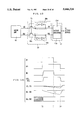
- chip enable signal ZCE is set up to L level, and address signal is set up to an address A.
- clock signal CLK rises to H level, and address signal Add and write mode designation signal ZWE are incorporated and latched in the address registers and mode register 6, respectively, at the rising edge of clock signal CLK because hip enable signal ZCE is at L level indicating that the memory device is selected.
- the latched signals Add and ZWE in the registers 3 and 6 are maintained therein until application of next L level of chip enable signal ZCE (at time T0).
- Write mode designation signal ZWE is set to H level at the rising edge of clock signal CLK (at time T0), and data read out operation mode is designated. Responsively, the read/write mode designation signal R/ZW from mode register 6 is brought to H level.
- address signal bits Ax1-Axn are applied to NAND circuit 8-1 of each unit decoder 8a in word line select decoder 8.
- NOT circuit (inverter) 8-2 When all address signal bits are at H level, NOT circuit (inverter) 8-2 generates an H level signal onto word line 9, and word line drive signal WL is raised to H level.
- access transistors 13-1 and 13-2 in memory cell 13 turn on to connect the storage nodes NA and NB to bit lines 12-1 and 12-2, respectively.
- driver transistor 13-3 is in an off state, and node NA is supplied with (positive) electric charges through resistance element 13-5 and is at H level.
- Driver transistor 13-4 is in an on-state, and node NB is kept at L level through discharging by the conducting driver transistor 13-4.
- Bit line 12-1 is maintained at H level of Vcc.
- Z address signal bits AYm-AYn are applied to NAND circuit 10-1 in block decoder 10R, and Y address signal bits AY1-AYl are applied to NAND circuit 10-2 in column decoder 10b.
- block select signal BSL goes low
- column select signal CSL goes high.
- Bit line select transfer gate 11 is made conductive in response to column select signal at H level, to connect the bit lines 12-1 and 12-2 with internal data input/output lines 15-1 and 15-2.
- NOR circuits 16-2, 20-2 and 20-3 each supply an L level signal, and inverters 20a and 20b are enabled to supply H level signals at power supply potential Vcc onto internal data input/output lines 15-1 and 15-2.
- inverter 16-1 in sense amplifier 16 supplies an L level signal in response to the signal R/ZW at H level. Therefore, in the selected memory block, the block select signal BSL is at L level, and NOR circuit 162 supplies H level signal to the gates of p channel MOS transistors 20-5 and 20-7. NOR circuits 20-2 and 20-3 supply L level signals to the respective gates of n channel MOS transistors 20-8 and 20-9. Thus, inverters 20a and 20b are brought into output high impedance state.
- bit lines 12-1 and 12-2 are coupled to internal data input/output lines 15-1 and 15-2, the potentials IO and /IO on the lines 15-1 and 15-2 change in accordance with the bit line potentials BL and /BL.
- MOS transistor 16-2 In sense amplifier 16, the output signal of NOR circuit 16-2 is at H level, and MOS transistor 16-2 is turned on to activate differential amplifier 16a.
- the potential IO is higher than the potential /IO and MOS transistor 16-4 is in a stronger on-state than MOS transistor 16-5 is MOS transistors 16-6 and 16-7 constitute a current mirror circuit and supply current flows of the same magnitude when they are the same in size with each other. Current flowing through MOS transistor 16-5 is smaller than the current flowing through MOS transistor 16-4 and is mirrored by MOS transistors 16-7 and 16-6 to be supplied to MOS transistor 16-4 Thus, the potential /RD at node NC is made lower than the potential RD at node ND.
- MOS transistor 16-4 As the current flowing through MOS transistor 16-4 increases, the current flowing through MOS transistor 16-5 decreases, and MOS transistors 16-6 and 16-7 approach off-state. Potential /RD is further decreased, or amplified, and then data signals /RD and RD are latched in data register 17. Data register 17 supplies the latch data signals RD and/RD as read out data Q and at a second rising edge of clock signal CLK at time T1.
- chip enable signal ZCE is set to L level at the rising edge of clock signal.
- Address signal Add designates an address A' which in turn is in another memory block, and word line drive signal WL on word line 9 goes low because word line select decoder 8 selects another word line.
- Block select signal BSL goes high, and NOR circuits 16-2, 20-2 and 20-3 supply H level signals, and the potentials BL, /BL and IO, /IO are precharged by NOT circuits 2a and 2b.
- the differential amplifier 16a is deactivated in response to block select signal BSL at H level, and potentials RD and /RD are raised to H level by MOS transistors 16-6 and 16-7.
- column select signal CSL is made low, and bit line select transfer gate 11 is made non-conductive, and bit lines 12-1 and 12-2 are isolated from internal data input/output lines 15-1 and 15-2.
- This memory block returns to the standby state, and memory cell selection operation is performed in the other selected memory block.
- write mode designation signal ZWE is set at low level at the rising edge of clock signal CLK, and internal read/write mode designation signal R/ZW from mode register 6 is made low.
- word line select driver 8 selects the word line 9, and word line drive signal WL on the selected word line 9 is raised to H level. Responsively, access transistors 13-1 and 13-2 are turned on to connect the storage nodes NA and NB to bit lines 12-1 and 12-2, respectively.
- bit line select decoder 10 falls block select signal BSL to L level in accordance with Z address signal bits AYm-AYn, and then raises column select signal CSL to H level in accordance with block select signal BSL and Y address signal bits AY1-AYl.
- Bit line select transfer gate 11 is made conductive to connect bit lines 12-1 and 12-2 to internal data input/output lines 15-1 and 15-2 in response to column select signal CSL at H level.
- Internal read/write mode designation signal R/ZW is at L level
- NOT circuit 16-1 supplies an H level signal
- NOR circuit 16-2 generates an output signal at L level to deactivate the differential amplifier 16a.
- NOT circuit 20-1 supplies an L level signal in response to internal write data WD at H level
- NOR circuit 20-2 supplies an output signal at L level in response to the signal R/ZW at L level, the output signal at L level from NOT circuit 20-1 and block select signal BSL at L level
- NOR circuit 20-3 outputs a signal at H level in response to internal write data at H level.
- MOS transistors 20-5 and 20-7 are made conductive in response to the L level signal from NOR circuit 16-2, MOS transistors 20-4 and 20-9 are made conductive, and MOS transistors 20-6 and 20-8 are made non-conductive.
- the potential IO is maintained at H level by MOS transistors 20-4 and 20-5, while the potential /IO is discharged to L level of GD ground level by MOS transistor 20-9.
- bit line select transfer gate 11 When bit line select transfer gate 11 is made conductive in response to column select signal CSL, the potentials IO and /IO are transferred to bit lines 12-1 and 12-2, and bit line potentials BL and /BL change in accordance with the potentials IO and /IO. Since access transistors 13-1 and 13-2 are in conductive states in response to word line dive signal WL, bit line potentials BL and /BL are transferred to storage nodes NA and NB. More specifically, H level potential (/BL) is transferred to the node NB to turn on driver transistor 13-3, and L level potential (BL) is transferred to the node NA to turn off driver transistor 13-4, and L level data is stored in the selected memory cell.
- data register 17 latches a new write data D' to generate a corresponding internal write data WD (at H level in FIG. 4).
- Address signal Add is also latched into address register 5, and address signal bits AXY1-AXn and AY1-AYn are generated.
- This newly applied address signal Add designates an address A' in another memory block, and this selected memory block is brought into non-selected state. That is, word line drive signal WL and column select signal CSL1 are turned to L level, and block select signal BSL is turned to H level.
- Bit line potentials BL and /BL are charges to H level at Vcc level by bit line load 14, and the input/output line potentials IO and /IO are charged to H level at Vcc level by the inverters 20a and 20b.
- data read or write can be performed in one clock cycle.
- External signals such as the address signal, the chip enable signal and the write mode designation signal are incorporated and latched at the rising edge of the clock signal, and there is no need for considering the skew of these external signals, and therefore for considering the timing margins of these signals.
- internal operation starting timing can be made faster.
- At least one word line is always in the selected state as far as the memory device (chip) is in the selected or operable state.
- a current flows from bit line load 14 to the ground node through bit line pair 12 and memory cell (including driver transistor).
- a word line connects a plurality (one row) of memory cells, and the current flowing through memory cells becomes significantly large.
- Sense amplifier 16 includes a current mirror type differential amplifier 16a, which in turn causes a current flow from the power supply node to the ground node through the current mirror stage and comparing MOS transistors when activated.
- Write driver 20 includes three state inverters 20a and 20b of CMOS configuration, and a current flows from bit line load 14, through bit line pair 12, internal data input/output line pair 15 and the conducting n channel MOS transistor in the inverter 20a or 20b supplying L level signal, to the ground node.
- One of sense amplifier 16 and write driver 20 is always activated as far as the memory device is set into the operable (enabled) state. These current flows are both nonnegligible in view of recent trend of reduction of current consumption of a memory device. Particularly, as the number of data bits is increased, the number of operating sense amplifiers or write drivers is increased, and the current consumption becomes greater accordingly.
- An object of the present invention is to provide a synchronous semiconductor memory device having current consumption reduced.
- Another object of the present invention is to provide a synchronous static random access memory device with current consumption in operation reduced.
- a synchronous memory device includes a controller for generating a plurality of pulse signals having different pulse widths in synchronization with the external clock signal to activate internal operations.
- a pulse width of a pulse signal activating a row (word line) selection operation is made shorter than that of pulse signals activating operations of a column (bit line pair) selection and data reading/writing on a selected memory cell.
- FIG. 1 shows an overall arrangement of a conventional synchronous semiconductor memory device.
- FIG. 2 shows a main portion of the memory device of FIG. 1 in detail.
- FIG. 3 is a waveform diagram representing a data read operation of the memory device of FIG. 2.
- FIG. 4 is a waveform diagram representing a data write operation of the memory device of FIG. 2.
- FIG. 5 shows an overall arrangement of a synchronous semiconductor memory device according to an embodiment of the present invention.
- FIG. 6 specifically shows a configuration of the clock pulse generator shown in FIG. 5.
- FIG. 7 is a waveform diagram representing an operation of the clock pulse generator shown in FIG. 6.
- FIG. 8A shows a specific example of the address register shown in FIG. 5.
- FIG. 8B is a timing chart representing an operation of the address register.
- FIG. 9 shows another structure of address register of FIG. 5.
- FIG. 10 shows a main portion of the semiconductor memory device of FIG. 5 in detail.
- FIG. 11 is a waveform diagram representing a data read operation of the memory device of FIG. 10.
- FIG. 12 is a waveform diagram representing a data write operation of the memory device of FIG. 10.
- FIG. 13 shows a modification of a data read portion of the semiconductor memory device.
- FIG. 14 is a waveform diagram used for explaining a meritorious effect of the arrangement of FIG. 13.
- FIG. 15 shows another embodiment of the clock pulse generator shown in FIG. 5.
- FIGS. 16A and 16B are waveform diagrams representing the operations of the clock pulse generator shown in FIG. 15.
- FIG. 17 shows a specific arrangement of the mode register of FIG. 5.
- FIG. 18 is a timing chart showing the states of external signals shown in FIG. 17 in a data reading operation.
- FIG. 19 is a timing chart showing the states of the external signals shown in FIG. 17 in a data write operation.
- FIG. 20 shows a modification of logic gate controlling the generation of internal clock pulses.
- FIG. 5 shows an overall arrangement of a synchronous semiconductor memory device according to an embodiment of the present invention.
- the memory device includes a plurality of memory blocks B#0-B#n each including memory cells 13 disposed in rows and columns, a plurality of word lines 9 disposed corresponding to respective rows, and a plurality of bit line pairs 12 disposed corresponding to respective columns, as in the arrangement shown in FIG. 1.
- the memory device further includes address register 5 incorporating an externally applied address signal to generate internal address signals AX and AY in response to an output signal of mode register 6 and in synchronization with an externally applied clock signal CLK, a word line select decoder 8 receiving and decoding the internal address signal AX to select a word line when activated, a plurality of local read/write circuits LC#0-LC#n provided for respective memory blocks B#0-B#n, for reading or writing data from or to a selected memory cell when activated, a data register 17 for communicating data with an activated local read/write circuit, and an output buffer 18 receiving data from data register 17 for outputting to a data input/output terminal 19.
- address register 5 incorporating an externally applied address signal to generate internal address signals AX and AY in response to an output signal of mode register 6 and in synchronization with an externally applied clock signal CLK
- a word line select decoder 8 receiving and decoding the internal address signal AX to select a word line when activated
- Local read/write circuits LC#0-LC#n each include a bit line select decoder 10 receiving and decoding the internal address signal AY to produce a block select signal BSL and a column select signal CSL when activated, a column select transfer gate 11 provided for each bit line pair 12, for coupling a corresponding bit line pair 12 to an internal data input/output line pair 15 in response to the column select signal CSL, a sense amplifier 16 responsive to block select signal BSL and a read/write mode designation signal R/ZW for differentially amplifying the potentials IO and /IO on the input/output line pair 15, and a write driver 20 for driving the internal data input/output line pair 15 in response to an internal write data WD when activated.
- a bit line select decoder 10 receiving and decoding the internal address signal AY to produce a block select signal BSL and a column select signal CSL when activated
- a column select transfer gate 11 provided for each bit line pair 12, for coupling a corresponding bit line pair 12 to an internal data input
- the memory device further includes a clock pulse generator (CLK GEN) 7 receiving the external clock signal CLK to generate a plurality of internal clock pulses having different pulse widths (active periods) from each other.
- CLK GEN clock pulse generator
- the internal clock pulses are activated in synchronization with an activation (rising) of the clock signal CLK and are deactivated internally in predetermined times.
- clock pulse generator 7 supplies a clock pulse P1 to word line select decoder 8 and another clock pulse P2 to bit line select decoder 10 in each local read/write circuit LC#0-LC#n. Active periods of these decoders 8 and 10 are determined by the activation periods of clock pulses P1 and P2. Now, operation of the memory device will be described briefly.
- chip enable signal ZCE When chip enable signal ZCE is set at low level to designate a chip select state, multibit address signal Add at address input terminals 1 and write mode designation signal ZWE are latched into address register 5 and mode register 6, respectively at the rising edge of clock signal CLK.
- Clock generator 7 normally operates to generate a plurality of kinds of clock pulses in accordance with the received clock signal CLK.
- Word line select decoder 8 is enabled in response to internal clock pulse P1 to decode internal address signal AX to drive an addressed word line (row) 9 into a selected state.
- Bit line select decoder 10 is enabled in response to clock pulse P2 to decode internal address signal AY to drive a column select signal CSL for an addressed column into a selected (H level) state to turn on a corresponding bit line select transfer gate 11. Thus, a memory cell 13 on the selected word line 9 and the selected bit line pair 12 is selected.
- sense amplifier 16 is activated in response to internal read/write mode designation signal R/ZW, to amplify the data of the selected memory cell 13 received through bit line pair 12 and internal input/output line pair 15 for outputting to data register 17.
- data register 17 transfers the latched data to output buffer 18, which in turn supplies the read out data at data input/output terminal 19.
- write driver 20 is activated in response to the internal read/write mode designation signal R/ZW and block select signal BSL and drives the selected bit line pair 12 into a state corresponding to external write data at the terminal 19 through internal input/output line pair 15 and bit line select transfer gate 11 in accordance with internal write data WD received from data register
- Activation period of word line drive signal WL, or enabling period of word line select decoder 8 is determined by the active period, or pulse width of clock pulse P1, while activation period of column select signal CSL and block select signal BSL, or enabling period of bit line select decoder 10 is determined by the active period of clock pulse P2.
- appropriate selection of the active periods of clock pulses P1 and P2 will reduce the current consumption in the enabled memory device because memory cell 13, sense amplifier 16 and write driver 20 are brought into non-selected states at appropriate timings in a clock cycle.
- FIG. 6 specifically shows a configuration of clock pulse generator 7 shown in FIG. 5.
- clock pulse generator 7 includes a delay circuit 7-1 delaying the clock signal CLK received through the clock input terminal 4 by a delay time ⁇ D1, a NOT circuit 7-2 receiving and inverting an output signal of delay circuit 7-2, and an NAND circuit 7-3 receiving and performing a negative logical product operation on an output signal of NOT circuit 7-2 and clock signal CLK.
- NOT circuit 7-2 has a delay time of ⁇ I
- NAND circuit 7-3 has a delay time of ⁇ N1.
- NAND circuit 7-3 supplies an output signal ⁇ 1 going low in response to the rise of clock signal CLK.
- Clock pulse generator 7 further includes cross-coupled NAND circuits 7-4 and 7-8, a delay circuit 7-9 delaying an output signal ⁇ 2 of NAND circuit 7-8 by ⁇ D2 for transmission to one input of NAND circuit 7-8, cross-coupled NAND circuits 7-5 and 7-10, and a delay circuit 7-11 delaying an output signal of NAND circuit 7-10 by a delay time of ⁇ D3.
- NAND circuit 7-4 receives the output signal ⁇ 1 at one input and the output signal ⁇ 2 at another input to produce the clock pulse P1, and has a delay time of ⁇ N2.
- NAND circuit 7-8 receives the clock pulse P1 at another input, and has a delay time of ⁇ N3.
- NAND circuit 7-5 receives the output signal ⁇ 1 at one input and an output signal of NAND circuit 7-10 to perform NAND operation thereon to produce the clock pulse P2, and has a delay time of ⁇ N4.
- NAND circuit 7-10 receives the clock signal P2 at one input and an output signal of delay circuit 7-11, and has a delay time of ⁇ D3.
- Clock pulse generator 7 further includes a reset transistor 7-6 formed of n channel MOS transistor responsive to a power on reset signal POR for resetting the clock pulse P1 to L level, and a reset transistor 7-7 formed of an n channel MOS transistor responsive to power on reset signal POR for resetting the clock pulse P2 to L level.
- Power on reset signal POR is made high for a predetermined time upon application of power supply voltage Vcc, and is generated by a well known circuit as disclosed in Japanese Patent Laying-Open No. 7-24379, for example. Now, an operation of the clock pulse generator 7 will be described with reference to an operating waveform diagram of FIG. 7.
- power on reset signal POR is made high for a predetermined time to turn on reset transistors 7-6 and 7-7, and clock pulses P1 and P2 are initialized to L level. This operation is not represented in FIG. 7.
- the clock pulse P1 is initialized to L level, and the output signal ⁇ 2 and the output signal of delay circuit 7-9 are at H level still at this time.
- the clock pulse P1 goes high through NAND circuit 7-4 at time T0+ ⁇ N1+ ⁇ N2, and then the output signal ⁇ 2 goes low through NAND circuit 7-3 at time T0+ ⁇ N1+ ⁇ N2+ ⁇ N3.
- the output signal of delay circuit 7-9 goes low, and responsively the output signal ⁇ 2 of NAND circuit 7-8 goes high.
- the output signal ⁇ 2 is kept low for a time of ⁇ D2+ ⁇ N3.
- the clock pulse P1 goes low after the elapse of time ⁇ N2.
- the clock pulse P1 is kept high for a time of ⁇ N2+2 ⁇ N3+ ⁇ D2.
- NAND circuit 7-5 In response to the rise of the output signal of NAND circuit 7-10, NAND circuit 7-5 receives H level signals a both inputs to bring the clock pulse P2 into L level after the elapse of a time of ⁇ N4 since the rise of the output signal of NAND circuit 7-10. Thus, the clock pulse P2 is kept high for a time of ⁇ N4+2 ⁇ N5+ ⁇ D3.
- delay circuits 7-9 and 7-11 each are formed of cascaded inverters of an even number of stages, the number of stages of inverters in a delay circuit 7-9 is made smaller than that in delay circuit 7-11 in practice, and the delay time ⁇ D2 of delay circuit 7-9 is made shorter than the delay time ⁇ D3 of delay circuit 7-11, that is, the active period of clock pulse P1 is made shorter than the active period of clock pulse P2 as shown by the dotted lines in FIG. 7, for the reason described later.
- FIG. 8A shows a schematic arrangement for one address signal bit Addi of the address register 5 and a configuration of mode register 6 for address latch control. The detailed configuration of mode register will be described later.
- mode register 6 includes a NOR circuit 6-1 receiving the clock signal CLK and chip enable signal ZCE.
- Address register 5 includes a transfer gate 5-1 formed of an n channel MOS transistor for example and responsive to an output signal of NOR circuit 6-1 for transferring an address signal bit Addi, NOT circuits 5-2 and 5-3 constituting a latch for latching a signal received from transfer gate 6-1, and a NOT circuit 5-4 receiving and inverting an output signal of NOT circuit 5-2 to generate an internal address signal bit Ai.
- a transfer gate 5-1 formed of an n channel MOS transistor for example and responsive to an output signal of NOR circuit 6-1 for transferring an address signal bit Addi
- NOT circuits 5-2 and 5-3 constituting a latch for latching a signal received from transfer gate 6-1
- a NOT circuit 5-4 receiving and inverting an output signal of NOT circuit 5-2 to generate an internal address signal bit Ai.
- chip enable signal ZCE is made low, an address signal bit Addi is applied and set up.
- Clock signal CLK is at L level, and transfer gate 5-1 is made conductive, and address signal bit Addi is transferred through transfer gate 5-1 to be latched by NOT circuits 5-2 and 5-3.
- chip enable signal ZCE When chip enable signal ZCE is set high at the rising edge of clock signal CLK at time T1, the output signal of NOR circuit 6-1 is at L level, and transfer gate 6-1 is kept non-conductive, and the address signal bit Ai is kept unchanged.
- chip enable signal ZCE When chip enable signal ZCE is set at L level before the rising edge of clock signal CLK at time T2, the output signal of NOR circuit 6-1 goes low to make transfer gate conductive, and a new address signal bit A1 is incorporated into the address register 5.
- FIG. 9 shows another arrangement of address register of one bit.
- mode register 6 includes a logic gate 6-2 receiving the clock signal CLK at a true input and chip enable signal ZCE at a false input.
- Address register 5 includes an up-edge trigger type register 5a having a clock input receiving the clock signal CLK, a signal input D receiving the address signal bit Addi, and a signal output Q outputting the internal address signal bit Ai.
- the register 5a has a well known internal configuration, and incorporates and latches the bit Addi at signal input D in response to the rising of the output of logic gate 6-2.
- Logic gate 6-2 has the output signal raised to H level at the rising of clock signal CLK while the chip enable signal ZCE is at L level.
- the address signal bit Addi is incorporated and latched into the address register 5 at the rising edge of clock signal when chip enable signal ZCE is at L level.
- Data register 17 has a configuration similar to the address register 5 except that a latch timing signal therefor is produced by the combination of clock signal CLK, chip enable signal ZCE and write mode designation signal ZWE. A specific configuration of mode register will be described later.
- FIG. 10 shows a detailed configuration of a memory cell and peripheral circuitry of the memory device of FIG. 5.
- word line select decoder 8 includes a unit decoder 8b provided for each word line 9 and enabled in response to internal clock signal P1 to decode row address bits AX1-AXn for driving a corresponding word line 9 into a selected state.
- Unit decoder 8b includes a NAND circuit 8-1 receiving address signal bits AX1-AXn and internal clock signal P1, and a NOT circuit 8-2 to drive a word line drive signal WL in accordance with the output signal of NAND circuit 8-1.
- the address signal bits AX1-AXn and internal clock signal P1 are all at H level, the word line 9 is selected.
- NAND circuit 8-1 is enabled only when internal clock signal P1 is at H level, and therefore activation period of word line drive signal WL is determined by H period or activation period of internal clock pulse P1.
- Bit line select decoder 10 includes a block decoder 10 provided for each memory block and receiving block address signal bits AYm-AYn and internal clock signal P2 to produce a block select signal BSL, and a unit column decoder 10b provided for each bit line pair 12 and receiving the block select signal BSL from block decoder and column address signal bits AY1-AYl to produce and supply a column select signal CSL to bit line select transfer gate 11.
- Block decoder 10c includes a NAND circuit 10-1 receiving block address signal bits AYm-AYn and internal clock signal P2 to produce block select signal BSL, and a NOT circuit 10-3 receiving block select signal BSL for inversion.
- Unit column decoder 10b includes a NAND circuit 10-2 receiving an output signal of NOT circuit 10-3 and column address signal bits AY1-AYl, and a NOT circuit 10-4 receiving an output signal of NAND circuit 10-2 to produce the column select signal CSL.
- NAND circuit 10-1 is enabled when internal clock pulse P2 is activated, or at H level, and therefore the activation period, or L level period of block select signal BSL is determined by internal clock pulse P2.
- Bit line load 14 memory cell 13, bit line select transfer gate 11, sense amplifier 16 and write driver 20 each have a configuration similar to that shown in FIG. 2, and like reference numerals or characters are denoted to like components. Now, operation of the memory device according to the present invention will be described with reference to operation waveform diagrams of FIGS. 11 and 12.
- chip enable signal ZCE is set to L level, and the external address signal Add (A) is latched into address register 5, and internal address signal bits AX1-AXn and AY1-AYn are defined and supplied to word line select decoder 8 and bit line select decoder 10.
- Write mode designation signal ZWE is at H level, and data read/write mode designation signal R/ZW from mode register 6 goes high at the rising edge of clock signal CLK at time T0.
- NOR circuits 20-2 and 20-3 supply L level signals to the gates of MOS transistors 20-4, 20-8 and 20-6, 20-9 in write driver 20.
- word line drive signal WL goes high, and access transistors 13-1 and 13-2 turn on to couple the storage nodes NA and NB to bit line 12-1 and 12-2, respectively.
- Bit line potentials BL and /BL precharged at H level of Vcc change in accordance with the potentials at storage nodes NA and NB.
- block select signal BSL from block decoder 10c goes low when block address signal bits (most significant Y address signal bits) designate the memory block.
- Unit column decoder 10b is enabled to decode column address signal bits (least significant Y address signal bits) AY1-AYl and drives the column select signal CSL to H level when column address signal bits AY1-AYl designate the shown bit lines 12-1 and 12-2.
- Internal data input/output lines 15-1 and 15-2 precharged to H level by write driver 20 are coupled to bit lines 12-1 and 12-2 through bit line select transfer gate transistors 11-1 and 11-2 made conductive in response to column select signal CSL at H level.
- Potentials IO and /IO change in accordance with bit line potentials BL and /BL, and differentially amplified by sense amplifier 16 (differential amplifier 16a) to produce internal read data signals RD and /RD.
- Amplified data signals RD and /RD are latched by data register 17.
- memory cell 13 is disconnected from bit lines 12-1 and 12-2, which in turn are isolated from internal data input/output lines 15-1 and 15-2.
- Output signal of NOR circuit 16-1 goes low to deactivate the differential amplifier 16a and to turn on MOS transistors 20-5 and 20-7 in inverters 20a and 20b.
- Bit lines 12-1 and 12-2 are precharged to H level by bit line load 14, and internal data input/output lines 15-1 and 15-2 are precharged to H level of Vcc level through p channel MOS transistors 20-4, 20-5 and 20-6, 20-7, respectively.
- clock signal CLK rises, and data in data register 17 is applied to data input/output terminal 19 through output buffer 18.
- Activation period of internal clock pulse P1 is made shorter than that of internal clock pulse P2.
- Internal data input/output lines 15-1 and 15-2 each provided in common for the bit lines in the memory block, and has a relatively large parasitic (line) capacitance as compared to bit lines 12-1 and 12-2. Therefore, even when word line 9 is brought into non-selected state by internal clock pulse P1 and bit lines 12-1 and 12-2 are precharged by bit line load 14, the potentials IO and /IO maintains the potential difference.
- sense amplifier 16 has a sufficient time to sense and amplify the potential difference, and data can be correctly read out.
- chip enable signal ZCE and data write mode designation signal ZWE are set to L level, and write data D is applied to the terminal 19.
- address signal Add is latched into address register 5
- data read/write mode designation signal R/ZW is made low.
- write data D is latched into data register 17.
- word line drive signal WL is driven to H level byword line select decoder 8 in accordance with row address signal bits AX1-AXn
- block select signal BSL is driven to L level by block decoder 10c in accordance with block address signal bits AYm-AYn
- column select signal CSL is driven to H level by column decoder 10b in accordance with block select signal BSL and column address signal bits AY1-AYl.
- the signal R/ZW is at L level, and sense amplifier 16 is in an inactive state and the read out data signals RD and /RD are at H level as in a non-selected or standby state.
- NOR circuits 20-2 and 20-3 are enabled by the signals R/ZW and BSL, and generate data signals corresponding to write data latched in data register 17 for application to inverters 20a and 20b.
- Inverters 20a and 20b are enabled by the output signal at L level from NOR circuit 16-1 in sense amplifier 16, and drive the internal data input/output lines 15-1 and 15-2 precharged at H level of Vcc level to the H and L levels corresponding to the output signals of NOR circuits 20-2 and 20-3.
- the potentials IO and /IO are transferred to storage nodes NA and NB of memory cell 13 through bit lines 12-1 and 12-2 coupled to the input/output lines 15-1 and 15-2 through bit line select transfer gate 11 made conductive in response to column select signal CSL.
- bit line select transfer gate 11 When internal clock pulse P2 goes low, bit line select transfer gate 11 is made non-conductive, and word driver 20 is deactivated. Internal data input/output lines 15-1 and 15-2 are isolated from bit lines 12-1 and 12-2, and precharged to H level by word driver 20. Bit lines 12-1 and 12-2 are also precharged to H level through bit line load 14.
- chip enable signal ZCE and data write mode designation signal ZWE are set at L level, and data writing operation in accordance with write data D' and address signal Add (A') is performed as in the above described manner.
- the internal clock pulses P1 and P2 are activated during a period shorter than the cycle of clock signal CLK.
- internal activation period word line selection and bit line selection
- the activation periods of these internal clock pulses P1 an P2 may be made longer than one cycle of clock signal CLK.
- FIG. 13 shows a modification of the embodiment according to the present invention.
- a latch circuit 30 which is responsive to internal clock pulse P1 for latching internal read data signals RD and /RD is provided between sense amplifier 16 and an output register 17a included in data register 17.
- Latch circuit 30 includes a transfer gate circuit 30a responsive to internal clock signal P1 at H level for transferring the data signals RD and /RD, and latches 30b and 30c latching data signals received through transfer gate circuit 30a to supply the latching data RX, /RX to output register 17a.
- Output register 17a is formed of an up-edge trigger type latch circuit and latches the received data signals RX, /RX in response to the rise of clock signal CLK.
- FIG. 14 is an operation waveform diagram for describing the meritorious effect of the arrangement of FIG. 13.
- Transfer gate circuit 30a is made conductive in response to internal clock pulse P1, and the data signals RD and /RD are latched by the latches 30b and 30c.
- transfer gate circuit 30a in latch circuit 30 is turned off in response to internal clock pulse P1 at L level at time T1.
- the signals RX and /RX are reliably latched without any influence of the variation of the potentials IO and /IO.
- Output register 17a latches the data signals RX and /RX in response to the rise of clock signal CLK. Thus, correct data can be reliably output through the output buffer.
- FIG. 15 shows another embodiment of clock pulse generator.
- clock pulse generator 7 includes a clock pulse generating circuit 7a for generating clock pulses Pa and Pb in synchronization with clock signal CLK, and a clock switching circuit 7b for switching frequencies of internal clock pulses P1 and P2 in accordance with a frequency of clock signal CLK.
- Clock pulse generating circuit 7a has the same configuration as that of clock pulse generator shown in FIG. 6. The detailed description of the circuit 7a will be omitted, and corresponding components are allotted with like reference numerals.
- Pulses Pa and Pb are activated for predetermined periods in response to rising of clock signal CLK.
- Clock switching circuit 7b includes a delay circuit 7-12 receiving and delaying by a delay time of ⁇ D4 the clock signal CLK, a delay circuit 7-13 receiving and delaying by a delay time of ⁇ D5 the clock signal CLK, a NOT circuit 7-14 having a delay time of ⁇ I1 and inverting an output signal of delay circuit 7-13, a NAND circuit 7-15 having a delay time of ⁇ N6 and receiving an output signal ⁇ 3 of delay circuit 7-12 and an output signal ⁇ 4 of NOT circuit for performing NAND (negative logical product) operation on the received signals ⁇ 3 and ⁇ 4 to produce an output signal ⁇ 5.
- Delay time ⁇ D4 of delay circuit 7-12 is made shorter than the sum of delay time ⁇ D5 of delay circuit 7-13 and delay time ⁇ I1 of NOT circuit 7-14.
- Clock switching circuit 7b further includes a p channel MOS transistor 7-16 responsive to output signal ⁇ 5 of NAND circuit 7-15 for transferring clock signal CLK, a NOT circuit 7-17 inverting the output signal ⁇ 5, an n channel MOS transistor 7-18 responsive to an output signal of NOT circuit 7-17 for transferring the clock signal CLK, NOT circuits 7-19 and 7-20 constituting an inverter latch to latch the clock signal CLK transferred through MOS transistors 7-16 and 7-18.
- MOS transistors 7-16 and 7-18 constitutes a CMOS (complementary MOS) transmission gate.
- NOT circuit 7-19 inverts the clock signal CLK received through MOS transistors 7-16 and 7-18 to produce a clock control signal ⁇ 6.
- Clock switching circuit 7b further includes n channel MOS transistors 7-21 and 7-22 responsive to clock control signal ⁇ 6 for transferring the pulses Pa and Pb to produce internal clock pulses P1 and P2, respectively, and p channel MOS transistors 7-23 and 7-24 responsive to clock control signal ⁇ 6 for being made conductive complementarily to MOS transistors 7-21 and 7-22 to fix the clock pulses P1 and P2 to H level.
- n channel MOS transistors 7-21 and 7-22 responsive to clock control signal ⁇ 6 for transferring the pulses Pa and Pb to produce internal clock pulses P1 and P2, respectively
- p channel MOS transistors 7-23 and 7-24 responsive to clock control signal ⁇ 6 for being made conductive complementarily to MOS transistors 7-21 and 7-22 to fix the clock pulses P1 and P2 to H level.
- clock pulse generating circuit 7a Operation of clock pulse generating circuit 7a is the same as that of clock pulse generator 7 shown in FIG. 6, and description of the operation of the circuit 7a is omitted.
- MOS transistors 7-16 and 7-18 are made conductive to transfer the clock signal CLK, and the clock signal CLK is latched by NOT circuits 7-19 and 7-20. It is assumed here that clock signal CLK has a duty ratio of 50% and a cycle time of TA. If TA/2 ⁇ D4+ ⁇ N6 and TA> ⁇ D5+ ⁇ I1+ ⁇ N6, clock signal CLK at L level is normally transferred through MOS transistors 7-16 and 7-18 to be latched by NOT circuits 7-19 and 7-20. Therefore, the clock control signal ⁇ 6 is normally at H level, and MOS transistors 7-21 and 7-22 are made conductive while MOS transistors 7-23 and 7-24 are made non-conductive. Thus, pulses Pa and Pb are transferred to be internal clock pulses P1 and P2.
- clock signal CLK has a duty ratio of 50% and a cycle time of TB.
- the signal ⁇ 5 is at H level.
- An input of NOT circuit 7-19 is at L level at the initial state and MOS transistors 7-16 and 7-18 are off, and the clock control signal ⁇ 6 is at H level.
- clock signal CLK When clock signal CLK is applied and rises to H level at time T0, the signal ⁇ 5 falls to L level at time T0+ ⁇ D4+ ⁇ N6, clock signal CLK at H level is transferred through MOS transistors 7-16 and 7-18 to be latched by NOT circuits 7-19 and 7-20, and the clock control signal ⁇ 6 goes low. Responsively, n channel MOS transistors 7-21 and 7-22 are turned off, and p channel MOS transistors 7-23 and 7-24 are turned on. Thus, internal clock pulses P1 and P2 are set at H Level.
- the signal ⁇ 5 from NAND circuit 7-15 normally goes low when clock signal CLK is at H level, the clock control signal ⁇ 6 is normally at L level, and internal clock pulses P1 and P2 are fixed at H level irrespective of the levels of pulses Pa and Pb.
- Word line select decoder 8 and bit line select decoder 10 shown in FIG. 10 are not clocked under this state, and operate statistically in accordance with address signal bits received from the address register.
- Clock pulse generating circuit 7a has a finite frequency response characteristic, and may not follow the clock signal CLK if the clock signal CLK has a very high frequency. In this state, the pulses P1 and P2 (Pa and Pb) are not defined or the clock pulse generating circuit is brought into an oscillating state. In such a state, word line select decoder and bit line select decoder are not correctly clocked, if the clock switching circuit 7b is not provided.
- circuit 7a can follow the clock signal CLK, there may be a case where internal clock pulses are activated over a plurality of operation cycles (or clock cycles), and no correct clocking operation can be implemented.
- the clock control signal ⁇ 6 may be applied to an input of NAND circuit 7-3 to fix the signal ⁇ 1 at H level for clock signal CLK of a high frequency. Pulses Pa and Pb do not change the potential levels, and current consumption is reduced.
- FIG. 17 shows a further embodiment of the present invention, and particularly shows an arrangement of mode register 6 in detail.
- mode register 6 includes a logic gate 6-1 receiving an address advance signal ZADV and an external clock signal CLK to generate a first internal clock signal CLK1, a NOR gate 6-2 receiving an address status processor signal ZADSP and a first chip select signal ZS1, a logic gate 6-3 receiving first chip select signal ZS1 and complementary second chip select signals S2 and ZS2, a logic gate 6-4 receiving an address status controller signal ZADSC and an output signal of NOR circuit 6-2, an OR gate 6-5 receiving a write enable signal ZW and an output signal of NOR gate 6-2, an AND gate 6-6 receiving external clock signal CLK and an output signal of logic gate 6-4 to generate a second internal clock signal CLK2, and an OR gate 6-7 receiving first and second internal clock signals CLK1 and CLK2.
- Address advance signal ZADV designates an advance of an internal address in a burst mode.
- Address status controller signal ZADSC indicates that an access is requested by an external memory controller.
- Address status processor signal ZADSP indicates that an access is requested by an external processor.
- Write enable signal ZW indicates that data write operation is designated.
- Output enable signal ZOE indicates that data reading operation is designated.
- Chip select signals ZS1, S2 and ZS2 indicate that the chip (memory device) is selected, or the chip is requested of accessing. The use of chip select signals ZS1, S2 and ZS2 enables wired OR connection of output terminals of memory devices.
- Chip select signals ZS1, S2 and ZS2, address status controller signal ZADSC, address status processor signal ZADSP, and address advance signal ZADV correspond to chip enable signal ZCE.
- Write enable signal ZW and output enable signal ZOE correspond to write mode designation signal ZWE.
- Address register 5 includes an address register 5a for receiving and latching an address signal Add in synchronization with the rise of second clock signal CLK2, and a burst counter 5b latching two and outputting least significant address signal bits from address register 5a and advancing the latched address in response to the rise of first clock signal CLK1.
- Clock pulse generator 7 receives the output signal of OR gate 6-7, or first and second clock signals CLK1 and CLK2 to generate the internal clock pulses P1 and P2.
- Mode register 6 further includes a write register 6-8 responsive to the rise of clock signal CLK for incorporating and latching an inverted version of the output signal of OR gate 6-5, a CS (chip select) register 6-9 responsive to the rise of second internal clock signal CLK2 for incorporating and latching the output signal of logic gate 6-3, a delay CS register 6-10 responsive to the rise of clock signal CLK for incorporating and latching an output signal of CS register 6-10.
- a write register 6-8 responsive to the rise of clock signal CLK for incorporating and latching an inverted version of the output signal of OR gate 6-5
- a CS (chip select) register 6-9 responsive to the rise of second internal clock signal CLK2 for incorporating and latching the output signal of logic gate 6-3
- a delay CS register 6-10 responsive to the rise of clock signal CLK for incorporating and latching an output signal of CS register 6-10.
- the registers 6-8 through 6-10 each are formed of an up-edge trigger type latch.
- Delay CS register 6-10 latches the output signal preceding by one clock cycle of CS register 6-9 because clock signal CLK changes at an earlier timing than second internal clock signal CLK2.
- Mode register 6 further includes a NAND gate 6-11 receiving outputs of the registers 6-8 and 6-9 to produce a control signal driving the write driver, a logic gate 6-12 receiving the output signal of write register 6-8 at a false input thereof and the output signal of CS register 6-9 at a true input thereof to produce a sense amplifier driving signal, a logic gate 6-13 receiving the output signals of the registers 6-9 and 6-10 at true inputs thereof and output enable signal ZOE at a false input thereof, and an NAND gate 6-14 receiving the output signal (write driver driving signal) of NAND gate 6-11 and an output signal of logic gate 6-13 to produce an output buffer driving signal.
- Data register 17 (input register and output register) operate in response to clock signal CLK to latch applied data signals. Now, operation of the circuitry will be described with reference to timing charts of FIGS. 18 and 19.
- first chip select signal ZS1 among chip select signals ZS1, S2 and ZS2 is representatively shown.
- the signal ZADSC is set low and chip select signal ZS1 is set high.
- Logic gate 6-4 supplies an H level signal to AND circuit 6-6 which in turn passes the clock signal CLK to generate the second internal clock Signal CLK2.
- Address signal Add is latched into address register 5a, and clock pulse generator 7 generates the clock pulses P1 and P2 in response to the second clock signal CLK2.
- CS register 6-9 latches an L level signal from logic gate 6-3 in synchronization with second internal clock signal CLK2, to inhibit the operation of sense amplifier and write driver.
- Output enable signal ZOE is at H level, and the output signals of the gates 6-13 and 6-14 are at L level, and the output buffer is set in the output high impedance state (High-Z).
- the signals ZADSP and ZADSC are both set to L level, and the output signal of the gate 6-2 goes high, and responsively the output signals of the gates 6-4 and 6-5 go high.
- Second clock signal CLK2 is generated, and address signal Add (A1) is latched into address register 5a, and CS register 6-9 latches the H level signal from the gate 6-3 in synchronization with the clock signal CLK2.
- Clock pulses P1 and P2 are generated and memory cell selection operation is performed.
- the signals ZADSP, ZADSC, ZW and ZADV are set at H levels, and the logic gate 6-4 supplies an L level signal to inhibit the generation of second internal clock signal CLK2, and logic gate 6-1 is disabled to inhibit the generation of first internal clock signal CLK1.
- Address register 5a and burst counter 5b supply the address signal bits AX1-AXn and AY1-AYn latched in the clock cycle 1.
- Write register 6-8 latches the output signal at H level from OR gate 6-5 in synchronization with clock signal CLK to supply an L level signal.
- CS register 6-9 latches the H level signal latched in the clock cycle 1
- NAND gate 6-11 supplies an H level signal to inhibit the operation of the write driver
- the gate 6-12 supplies an H level signal to activate the operation of the sense amplifier.
- Output enable signal ZOE is at L level
- delay CS register 6-10 latches the H level signal from CS register 6-9 in synchronization with clock signal CLK
- AND gate 6-14 supplies an H level signal to enable the output buffer.
- the signals ZADSP and ZW are set to H level, and the signals ZADSC and ZS1 are set to L level.
- NOR gate 6-2 supplies an L level signal
- logic gate 6-4 supplies an H level signal, and the internal clock signal CLK2 is generated, and address signal Add is latched into address register 5a.
- Burst counter 5b receives two least significant Y address signal bits, and latches and outputs the same.
- Write register 6-8 latches the output signal at H level in synchronization with clock signal CLK to supply an L level signal.
- Chip select signal ZS1 is at L level
- the gate 6-3 supplies an H level signal
- CS register 6-9 latches the H level signal received from the gate 6-3 in response to the rise of the second internal clock signal CLK2.
- the gate 6-12 supplies an H level signal to operate the sense amplifier.
- Memory cell is selected in accordance with address signal bits AX1-AXn and AY1-AYn.
- Output enable signal ZOE is at H level, and the output buffer is at output high impedance state.
- the signals ZADV, ZADSC and ZW are set at H level, and the second clock signal CLK2 is maintained at L level, and the contents of address register 5a and CS register 6-9 are not changed.
- Write register 6-8 latches an H level signal to supply an L level signal.
- Delay CS register 6-10 latches the H level signal from CS register 6-9 in response to the rise of clock signal CLK.
- Address advance signal ZADV is at L level, and burst counter 5b advances the latched address in response to the first internal clock signal CLK1. Thus, a new memory cell is selected.
- output buffer is enabled in response to H level signal from AND gate 6-14, and data Q (A2) addressed by the address A2 and data Q (A2+1) and Q (A2+2) addressed by the advanced addresses are read out through the output buffer, and are made valid at the rise of clock signal CLK of clock cycles 5, 6 and 7.
- address advance signal ZADV is set to H level, and first clock signal CLK1 is not generated.
- Burst counter 5b does not advance the latched address, and memory cell data at address "A2+2" is again read out.
- Clock pulses P1 and P2 are not generated, and the output register continuously supplies the data Q (A2+2) in the cycle 7.
- address advance signal ZADV is made low to advance the address in the burst counter 5b in response to the first internal clock signal CLK1.
- Clock pulses P1 and P2 are generated in response to the first internal clock signal CLK1, and memory cell selection is performed, although the second internal clock signal CLK2 is not generated.
- data Q(A2+3), Q(A2) and Q (A2+1) are sequentially read out.
- the signals ZADSP and ZS1 are set at L level, and second internal clock signal CLK2 is generated and a new address A3 is latched into address register 5a.
- chip select signal ZS1 is set to H level, and address 5a is updated.
- CS register 6-9 supplies an L level signal to inhibit the operation of write driver and sense amplifier, and to bring the output buffer into output high impedance state.
- the signals ZADSP and ZW are set to H level, and the signals ZADSC and ZS1 are set to L level, and data read operation in accordance with the address A4 is performed.
- Memory cell is selected in one clock cycle and the selected memory cell data is read out in one clock cycle. Only when memory cell is selected, internal clock pulses P1 and P2 are generated and unnecessary generation of internal clock pulses P1 and P2 can be inhibited, and current consumption is reduced.
- output enable signal ZOE is set to H level, and the output buffer is set to output high impedance state.
- the signals ZADSP and ZS1 are set to L level, and address A1 is latched into address register 5a in response to second internal clock signal CLK2, and H level signal is latched in CS register 6-9.
- the signals ZADSP and ZADSC are set to H level to inhibit generation of second internal clock signal CLK2.
- the signal ZADV is at H level, and write enable signal ZW is set to L level.
- address A1 memory cell is selected and data D (A1) is written into the selected memory cell at address A1 in the cycle 2.
- the signals ZADSP and ZS1 are set to L level, and an address A2 is latched in address register 5a.
- the signals ZADSP, ZADSC and ZADV are set to H level, and the signal ZW is set to L level.
- Memory cell at address A2 is selected and data D (A2) is written into the selected memory cell.
- address advance signal ZADV and write enable signal ZW are set to L level, and burst counter 5b advances the latched address, and data D (A2+1) is written into the memory cell at the advanced address A2+1.
- the clock signal CLK1 is generated.
- the signal ZADV is set to H level, and the signal ZW is set to L level, burst counter 5b does not advance the address, and memory cell at address A2+1 is selected again.
- the signals ZADV and ZW are set to L level, and address is advanced and data D (A2+2) and D (A2+3) are written into the memory cells at the advanced addresses, respectively.
- the address advance signal ZADV is set to L level and first internal clock signal CLK1 is generated.
- the signal ZADV is set to H level, and the first internal clock signal CLK1 is not generated.
- Signals ZADSP and ZADSC are used to update an address latched in the address register 5a.
- FIG. 20 In order to reliably generate clock pulses P1 and P2 in a single write mode of operation, the construction of FIG. 20 is employed.
- a logic gate 6-20 receives the signals CLK, ZW, ZADV, ZADSP and ZADSC and generate an H level signal when only write enable signal ZW is at L level and the other signals CLK, ZADV, ZADSP and ZADSC are all at H level OR gate 6-22 receives the output signal of the gate 6-20 and the clock signals CLK1 and CLK2.
- OR gate 6-22 the output signal of OR gate 6-22 is raised whenever an accessing to a memory cell is carried out.
- the address bits from the burst counter are used to select a column.
- the output signal of OR gate 6-7 (or OR gate 6-22 of FIG. 20) is a trigger signal, and the one shot pulse generator formed of delay circuit 7-1, NOT circuit 7-2 and NAND circuit 7-3 in the clock pulse generator 7 as shown in FIG. 17 can be removed.
- the frequency switching circuit 7b shown in FIG. 15 receives the external clock signal CLK.
Landscapes
- Dram (AREA)
Abstract
Description
Claims (15)
Priority Applications (1)
| Application Number | Priority Date | Filing Date | Title |
|---|---|---|---|
| US08/616,386 US5666324A (en) | 1996-03-15 | 1996-03-15 | Clock synchronous semiconductor memory device having current consumption reduced |
Applications Claiming Priority (1)
| Application Number | Priority Date | Filing Date | Title |
|---|---|---|---|
| US08/616,386 US5666324A (en) | 1996-03-15 | 1996-03-15 | Clock synchronous semiconductor memory device having current consumption reduced |
Publications (1)
| Publication Number | Publication Date |
|---|---|
| US5666324A true US5666324A (en) | 1997-09-09 |
Family
ID=24469222
Family Applications (1)
| Application Number | Title | Priority Date | Filing Date |
|---|---|---|---|
| US08/616,386 Expired - Lifetime US5666324A (en) | 1996-03-15 | 1996-03-15 | Clock synchronous semiconductor memory device having current consumption reduced |
Country Status (1)
| Country | Link |
|---|---|
| US (1) | US5666324A (en) |
Cited By (27)
| Publication number | Priority date | Publication date | Assignee | Title |
|---|---|---|---|---|
| US5808961A (en) * | 1997-02-18 | 1998-09-15 | Mitsubishi Denki Kabushiki Kaisha | Internal clock generating circuit for clock synchronous type semiconductor memory device |
| US5808959A (en) * | 1996-08-07 | 1998-09-15 | Alliance Semiconductor Corporation | Staggered pipeline access scheme for synchronous random access memory |
| US5828622A (en) * | 1996-01-19 | 1998-10-27 | Stmicroelectronics, Inc. | Clocked sense amplifier with wordline tracking |
| US5914909A (en) * | 1996-08-23 | 1999-06-22 | Hyundai Electronics Industries Co., Ltd. | Semiconductor memory device capable of driving the data bus sense amplifier in both read and write modes |
| US5926838A (en) * | 1997-03-19 | 1999-07-20 | Micron Electronics | Interface for high speed memory |
| US5978308A (en) * | 1996-02-28 | 1999-11-02 | Nec Corporation | Single-chip memory system having a decoder for pulse word line method |
| US6011728A (en) * | 1997-02-24 | 2000-01-04 | Kawasaki Steel Corporation | Synchronous memory with read and write mode |
| US6067256A (en) * | 1998-04-01 | 2000-05-23 | Mitsubishi Denki Kabushiki Kaisha | Static semiconductor memory device operating at high speed under lower power supply voltage |
| US6240044B1 (en) * | 1999-07-29 | 2001-05-29 | Fujitsu Limited | High speed address sequencer |
| US6349072B1 (en) * | 1999-11-05 | 2002-02-19 | Matsushita Electric Industrial Co., Ltd. | Random access memory device |
| US6378102B1 (en) * | 1996-04-22 | 2002-04-23 | Mitsubishi Denki Kabushiki Kaisha | Synchronous semiconductor memory device with multi-bank configuration |
| US6490206B2 (en) * | 2000-10-24 | 2002-12-03 | Samsung Electronics Co., Ltd. | High-speed synchronous semiconductor memory having multi-stage pipeline structure and operating method |
| US20040141404A1 (en) * | 1997-10-10 | 2004-07-22 | Rambus Inc. | Power control system for synchronous memory device |
| US20040233742A1 (en) * | 1999-07-16 | 2004-11-25 | Morzano Christopher K. | Apparatus and method for adusting clock skew |
| US20050060487A1 (en) * | 1998-03-10 | 2005-03-17 | Barth Richard M. | Memory device having a power down exit register |
| US20050128855A1 (en) * | 2003-12-15 | 2005-06-16 | Joshi Rajiv V. | Self timed bit and read/write pulse stretchers |
| US20060039217A1 (en) * | 2004-08-17 | 2006-02-23 | Neal Berger | Power efficient read circuit for a serial output memory device and method |
| US20060264013A1 (en) * | 2005-05-18 | 2006-11-23 | Hynix Semiconductor Inc. | Method for implanting ions to a wafer for manufacturing of semiconductor device and method of fabricating graded junction using the same |
| US20060268648A1 (en) * | 2005-05-11 | 2006-11-30 | Texas Instruments Incorporated | High performance, low-leakage static random access memory (SRAM) |
| US20070242538A1 (en) * | 2006-04-14 | 2007-10-18 | Qikai Chen | Apparatus and methods for determining memory device faults |
| US20080225624A1 (en) * | 2005-07-21 | 2008-09-18 | Micron Technology Inc. | High speed array pipeline architecture |
| US20090034347A1 (en) * | 2000-07-07 | 2009-02-05 | Mosaid Technologies Incorporated | High speed dram architecture with uniform access latency |
| US20120243360A1 (en) * | 2011-03-18 | 2012-09-27 | Richard Ferrant | Semiconductor memory having staggered sense amplifiers associated with a local column decoder |
| US20150036419A1 (en) * | 2013-07-31 | 2015-02-05 | Renesas Electronics Corporation | Semiconductor apparatus and data reading method |
| US9018980B1 (en) * | 2014-06-12 | 2015-04-28 | Xilinx, Inc. | Bimodal clock generator |
| US10388366B2 (en) * | 2011-03-04 | 2019-08-20 | Renesas Electronics Corporation | Semiconductor device |
| US20210304816A1 (en) * | 2020-03-30 | 2021-09-30 | Arm Limited | Column Multiplexer Circuitry |
Citations (7)
| Publication number | Priority date | Publication date | Assignee | Title |
|---|---|---|---|---|
| US5077693A (en) * | 1990-08-06 | 1991-12-31 | Motorola, Inc. | Dynamic random access memory |
| US5083296A (en) * | 1989-08-28 | 1992-01-21 | Hitachi, Ltd. | Semiconductor memory with alternately multiplexed row and column addressing |
| JPH06162770A (en) * | 1992-11-26 | 1994-06-10 | Matsushita Electric Ind Co Ltd | Semiconductor memory |
| JPH06203563A (en) * | 1992-10-02 | 1994-07-22 | Samsung Electron Co Ltd | Data-output buffer of synchronous semiconductor memory device |
| US5341341A (en) * | 1992-03-26 | 1994-08-23 | Nec Corporation | Dynamic random access memory device having addressing section and/or data transferring path arranged in pipeline architecture |
| JPH06333388A (en) * | 1993-05-19 | 1994-12-02 | Fujitsu Ltd | Semiconductor memory device |
| US5539693A (en) * | 1993-12-24 | 1996-07-23 | Nec Corporation | Method of controlling semiconductor storage circuit |
-
1996
- 1996-03-15 US US08/616,386 patent/US5666324A/en not_active Expired - Lifetime
Patent Citations (8)
| Publication number | Priority date | Publication date | Assignee | Title |
|---|---|---|---|---|
| US5083296A (en) * | 1989-08-28 | 1992-01-21 | Hitachi, Ltd. | Semiconductor memory with alternately multiplexed row and column addressing |
| US5077693A (en) * | 1990-08-06 | 1991-12-31 | Motorola, Inc. | Dynamic random access memory |
| US5341341A (en) * | 1992-03-26 | 1994-08-23 | Nec Corporation | Dynamic random access memory device having addressing section and/or data transferring path arranged in pipeline architecture |
| JPH06203563A (en) * | 1992-10-02 | 1994-07-22 | Samsung Electron Co Ltd | Data-output buffer of synchronous semiconductor memory device |
| US5384750A (en) * | 1992-10-02 | 1995-01-24 | Samsung Electronics Co., Ltd. | Data output buffer of a synchronous semiconductor memory device |
| JPH06162770A (en) * | 1992-11-26 | 1994-06-10 | Matsushita Electric Ind Co Ltd | Semiconductor memory |
| JPH06333388A (en) * | 1993-05-19 | 1994-12-02 | Fujitsu Ltd | Semiconductor memory device |
| US5539693A (en) * | 1993-12-24 | 1996-07-23 | Nec Corporation | Method of controlling semiconductor storage circuit |
Cited By (61)
| Publication number | Priority date | Publication date | Assignee | Title |
|---|---|---|---|---|
| US5828622A (en) * | 1996-01-19 | 1998-10-27 | Stmicroelectronics, Inc. | Clocked sense amplifier with wordline tracking |
| US5978308A (en) * | 1996-02-28 | 1999-11-02 | Nec Corporation | Single-chip memory system having a decoder for pulse word line method |
| US6378102B1 (en) * | 1996-04-22 | 2002-04-23 | Mitsubishi Denki Kabushiki Kaisha | Synchronous semiconductor memory device with multi-bank configuration |
| US5808959A (en) * | 1996-08-07 | 1998-09-15 | Alliance Semiconductor Corporation | Staggered pipeline access scheme for synchronous random access memory |
| US5872742A (en) * | 1996-08-07 | 1999-02-16 | Alliance Semiconductor Corporation | Staggered pipeline access scheme for synchronous random access memory |
| US5914909A (en) * | 1996-08-23 | 1999-06-22 | Hyundai Electronics Industries Co., Ltd. | Semiconductor memory device capable of driving the data bus sense amplifier in both read and write modes |
| US5808961A (en) * | 1997-02-18 | 1998-09-15 | Mitsubishi Denki Kabushiki Kaisha | Internal clock generating circuit for clock synchronous type semiconductor memory device |
| US6011728A (en) * | 1997-02-24 | 2000-01-04 | Kawasaki Steel Corporation | Synchronous memory with read and write mode |
| US5926838A (en) * | 1997-03-19 | 1999-07-20 | Micron Electronics | Interface for high speed memory |
| US8305839B2 (en) | 1997-10-10 | 2012-11-06 | Rambus Inc. | Memory device having multiple power modes |
| US7986584B2 (en) | 1997-10-10 | 2011-07-26 | Rambus Inc. | Memory device having multiple power modes |
| US8248884B2 (en) | 1997-10-10 | 2012-08-21 | Rambus Inc. | Method of controlling a memory device having multiple power modes |
| US20100046314A1 (en) * | 1997-10-10 | 2010-02-25 | Tsern Ely K | Memory Device Having a Read Pipeline and a Delay Locked Loop |
| US20040141404A1 (en) * | 1997-10-10 | 2004-07-22 | Rambus Inc. | Power control system for synchronous memory device |
| US7626880B2 (en) | 1997-10-10 | 2009-12-01 | Rambus Inc. | Memory device having a read pipeline and a delay locked loop |
| US7320082B2 (en) | 1997-10-10 | 2008-01-15 | Rambus Inc. | Power control system for synchronous memory device |
| US20050180255A1 (en) * | 1997-10-10 | 2005-08-18 | Tsern Ely K. | Memory device having a read pipeline and a delay locked loop |
| US20080002516A1 (en) * | 1997-10-10 | 2008-01-03 | Tsern Ely K | Memory Device Having a Delay Locked Loop and Multiple Power Modes |
| US20050120161A1 (en) * | 1998-03-10 | 2005-06-02 | Barth Richard M. | Methods of operation of a memory device and system |
| US20050216654A1 (en) * | 1998-03-10 | 2005-09-29 | Barth Richard M | System and module including a memory device having a power down mode |
| US20050235130A1 (en) * | 1998-03-10 | 2005-10-20 | Barth Richard M | System for a memory device having a power down mode and method |
| US8756395B2 (en) | 1998-03-10 | 2014-06-17 | Rambus Inc. | Controlling DRAM at time DRAM ready to receive command when exiting power down |
| US7574616B2 (en) | 1998-03-10 | 2009-08-11 | Rambus Inc. | Memory device having a power down exit register |
| US7581121B2 (en) | 1998-03-10 | 2009-08-25 | Rambus Inc. | System for a memory device having a power down mode and method |
| US7571330B2 (en) | 1998-03-10 | 2009-08-04 | Rambus Inc. | System and module including a memory device having a power down mode |
| US20050060487A1 (en) * | 1998-03-10 | 2005-03-17 | Barth Richard M. | Memory device having a power down exit register |
| US8127152B2 (en) | 1998-03-10 | 2012-02-28 | Rambus Inc. | Method of operation of a memory device and system including initialization at a first frequency and operation at a second frequency and a power down exit mode |
| US6067256A (en) * | 1998-04-01 | 2000-05-23 | Mitsubishi Denki Kabushiki Kaisha | Static semiconductor memory device operating at high speed under lower power supply voltage |
| US7116133B2 (en) * | 1999-07-16 | 2006-10-03 | Micron Technology, Inc. | Apparatus and method for adjusting clock skew |
| US20040233742A1 (en) * | 1999-07-16 | 2004-11-25 | Morzano Christopher K. | Apparatus and method for adusting clock skew |
| US20060250163A1 (en) * | 1999-07-16 | 2006-11-09 | Morzano Christopher K | Apparatus and method for adjusting clock skew |
| US6240044B1 (en) * | 1999-07-29 | 2001-05-29 | Fujitsu Limited | High speed address sequencer |
| US6349072B1 (en) * | 1999-11-05 | 2002-02-19 | Matsushita Electric Industrial Co., Ltd. | Random access memory device |
| US8045413B2 (en) | 2000-07-07 | 2011-10-25 | Mosaid Technologies Incorporated | High speed DRAM architecture with uniform access latency |
| US20100232237A1 (en) * | 2000-07-07 | 2010-09-16 | Mosaid Technologies Incorporated | High speed dram architecture with uniform access latency |
| US20090034347A1 (en) * | 2000-07-07 | 2009-02-05 | Mosaid Technologies Incorporated | High speed dram architecture with uniform access latency |
| US7751262B2 (en) * | 2000-07-07 | 2010-07-06 | Mosaid Technologies Incorporated | High speed DRAM architecture with uniform access latency |
| US8503250B2 (en) | 2000-07-07 | 2013-08-06 | Mosaid Technologies Incorporated | High speed DRAM architecture with uniform access latency |
| US6490206B2 (en) * | 2000-10-24 | 2002-12-03 | Samsung Electronics Co., Ltd. | High-speed synchronous semiconductor memory having multi-stage pipeline structure and operating method |
| US20050128855A1 (en) * | 2003-12-15 | 2005-06-16 | Joshi Rajiv V. | Self timed bit and read/write pulse stretchers |
| US7006403B2 (en) * | 2003-12-15 | 2006-02-28 | International Business Machines Corp. | Self timed bit and read/write pulse stretchers |
| US20060039217A1 (en) * | 2004-08-17 | 2006-02-23 | Neal Berger | Power efficient read circuit for a serial output memory device and method |
| US7027348B2 (en) * | 2004-08-17 | 2006-04-11 | Silicon Storage Technology, Inc. | Power efficient read circuit for a serial output memory device and method |
| US20060268648A1 (en) * | 2005-05-11 | 2006-11-30 | Texas Instruments Incorporated | High performance, low-leakage static random access memory (SRAM) |
| US7489584B2 (en) * | 2005-05-11 | 2009-02-10 | Texas Instruments Incorporated | High performance, low-leakage static random access memory (SRAM) |
| US20060264013A1 (en) * | 2005-05-18 | 2006-11-23 | Hynix Semiconductor Inc. | Method for implanting ions to a wafer for manufacturing of semiconductor device and method of fabricating graded junction using the same |
| US20080225624A1 (en) * | 2005-07-21 | 2008-09-18 | Micron Technology Inc. | High speed array pipeline architecture |
| US7616504B2 (en) | 2005-07-21 | 2009-11-10 | Micron Technology, Inc. | High speed array pipeline architecture |
| US7480202B2 (en) * | 2005-07-21 | 2009-01-20 | Micron Technology, Inc. | High speed array pipeline architecture |
| US20090129176A1 (en) * | 2005-07-21 | 2009-05-21 | Huy Vo | High Speed Array Pipeline Architecture |
| US20070242538A1 (en) * | 2006-04-14 | 2007-10-18 | Qikai Chen | Apparatus and methods for determining memory device faults |
| US7548473B2 (en) * | 2006-04-14 | 2009-06-16 | Purdue Research Foundation | Apparatus and methods for determining memory device faults |
| US10388366B2 (en) * | 2011-03-04 | 2019-08-20 | Renesas Electronics Corporation | Semiconductor device |
| US9159400B2 (en) * | 2011-03-18 | 2015-10-13 | Soitec | Semiconductor memory having staggered sense amplifiers associated with a local column decoder |
| US20120243360A1 (en) * | 2011-03-18 | 2012-09-27 | Richard Ferrant | Semiconductor memory having staggered sense amplifiers associated with a local column decoder |
| CN104347112A (en) * | 2013-07-31 | 2015-02-11 | 瑞萨电子株式会社 | Semiconductor apparatus and data reading method |
| US20150036419A1 (en) * | 2013-07-31 | 2015-02-05 | Renesas Electronics Corporation | Semiconductor apparatus and data reading method |
| US9018980B1 (en) * | 2014-06-12 | 2015-04-28 | Xilinx, Inc. | Bimodal clock generator |
| US20210304816A1 (en) * | 2020-03-30 | 2021-09-30 | Arm Limited | Column Multiplexer Circuitry |
| US11763880B2 (en) * | 2020-03-30 | 2023-09-19 | Arm Limited | Column multiplexer circuitry |
| US12230317B2 (en) * | 2020-03-30 | 2025-02-18 | Arm Limited | Column multiplexer circuitry |
Similar Documents
| Publication | Publication Date | Title |
|---|---|---|
| US5666324A (en) | Clock synchronous semiconductor memory device having current consumption reduced | |
| JP3903674B2 (en) | Semiconductor memory device | |
| US6069839A (en) | Circuit and method for implementing single-cycle read/write operation(s), and random access memory including the circuit and/or practicing the method | |
| USRE36851E (en) | Method and circuit for shortcircuiting data transfer lines and semiconductor memory device having the circuit | |
| US5754481A (en) | Clock synchronous type DRAM with latch | |
| US5555526A (en) | Synchronous semiconductor memory device having an auto-precharge function | |
| US6026035A (en) | Integrated circuit memory devices having improved precharge and I/O driver characteristics and methods of operating same | |
| JPH08279282A (en) | Integrated circuit memory | |
| US6556482B2 (en) | Semiconductor memory device | |
| US5357479A (en) | Static random access memory capable of preventing erroneous writing | |
| JPH09320286A (en) | Semiconductor memory | |
| US5278792A (en) | Semiconductor memory device with dummy cycle operation | |
| US6963499B2 (en) | Static RAM with flash-clear function | |
| US6356473B1 (en) | Static random access memory (SRAM) | |
| JPH08204161A (en) | Semiconductor memory device | |
| KR100280624B1 (en) | Bootstrap decoder circuit and its operation method | |
| US5511031A (en) | Semiconductor memory system having sense amplifier being activated late during clock cycle | |
| USRE36532E (en) | Synchronous semiconductor memory device having an auto-precharge function | |
| US6930952B2 (en) | Method of reading memory device in page mode and row decoder control circuit using the same | |
| EP0454162B1 (en) | Semiconductor memory device | |
| US6353574B1 (en) | Semiconductor memory device having pipe register operating at high speed | |
| KR100523507B1 (en) | Semiconductor memory device | |
| US7034572B2 (en) | Voltage level shifting circuit and method | |
| KR100650845B1 (en) | A buffer control circuit for reducing power consumption, a semiconductor memory device for a memory module including the same, and a control operation method thereof | |
| KR100224955B1 (en) | Semiconductor memory devices |
Legal Events
| Date | Code | Title | Description |
|---|---|---|---|
| AS | Assignment |
Owner name: MITSUBISHI DENKI KABUSHIKI KAISHA, JAPAN Free format text: ASSIGNMENT OF ASSIGNORS INTEREST;ASSIGNORS:KOSUGI, RYUICHI;OHBAYASHI, SHIGEKI;REEL/FRAME:007921/0262 Effective date: 19960306 |
|
| STCF | Information on status: patent grant |
Free format text: PATENTED CASE |
|
| FEPP | Fee payment procedure |
Free format text: PAYOR NUMBER ASSIGNED (ORIGINAL EVENT CODE: ASPN); ENTITY STATUS OF PATENT OWNER: LARGE ENTITY |
|
| FPAY | Fee payment |
Year of fee payment: 4 |
|
| FPAY | Fee payment |
Year of fee payment: 8 |
|
| FPAY | Fee payment |
Year of fee payment: 12 |
|
| AS | Assignment |
Owner name: RENESAS ELECTRONICS CORPORATION, JAPAN Free format text: ASSIGNMENT OF ASSIGNORS INTEREST;ASSIGNOR:MITSUBISHI DENKI KABUSHIKI KAISHA;REEL/FRAME:025980/0219 Effective date: 20110307 |