US5657261A - Interpolation of digital signals using signal sample replication - Google Patents
Interpolation of digital signals using signal sample replication Download PDFInfo
- Publication number
- US5657261A US5657261A US08/422,892 US42289295A US5657261A US 5657261 A US5657261 A US 5657261A US 42289295 A US42289295 A US 42289295A US 5657261 A US5657261 A US 5657261A
- Authority
- US
- United States
- Prior art keywords
- sample rate
- filter
- digital
- signal
- input signal
- Prior art date
- Legal status (The legal status is an assumption and is not a legal conclusion. Google has not performed a legal analysis and makes no representation as to the accuracy of the status listed.)
- Expired - Lifetime
Links
Images


Classifications
-
- G—PHYSICS
- G06—COMPUTING OR CALCULATING; COUNTING
- G06F—ELECTRIC DIGITAL DATA PROCESSING
- G06F17/00—Digital computing or data processing equipment or methods, specially adapted for specific functions
- G06F17/10—Complex mathematical operations
- G06F17/17—Function evaluation by approximation methods, e.g. inter- or extrapolation, smoothing, least mean square method
Definitions
- the present invention relates to interpolating filters, and more particularly, to an interpolating filter and filtering technique that uses signal sample replication in lieu of zero insertion to achieve interpolation of digital signals.
- the interpolator can be a simple sample and hold in the digital world according to the patent. There is no suggestion that a smoothing filter to remove the sample and hold artifacts be employed. Gingell does suggest that perhaps a simply constructed linear interpolator be used as being a little better than a sample and hold. The technique of Gingell follows the interpolator by other processing steps that increase the sample rate still farther. The digital to analog converter and the following analog filter are very simple as a result. The use of a filter as part of the interpolator that corrects the sample and hold frequency distortion is not suggested. Since there is no such filter, there is no consideration of the number of bits used in the quantization of the filter coefficients.
- U.S. Pat. No. 4,209,771 issued to Miyata et at. entitled "Code Converting Method and System” implements a scheme for conversion to a high rate differential pulse code system using ⁇ 1 values.
- the conversion uses the usual DPCM approach of a linearly rising value at a high rate that can reach the value of the digital samples at the sample times.
- the result is an approximation to a carefully interpolated signal that may be acceptable in some applications.
- the distortions that occur are well known. As long as the signal changes slowly, the DPCM can keep up with it. When the signal changes rapidly with a large swing, the DPCM approximation will depart from the input signal, causing distortions in the signal and generating spurious frequencies that can cause interchannel interference when there is more than one signal in the bandwidth of the digital samples.
- U.S. Pat. No. 5,126,737 issued to Torii entitled "Method for Converting a Digital Signal into Another Digital Signal Having a Different Sampling Frequency” uses interpolating to produce an output sample rate that is nearly the same as the input sample rate.
- the technique proposed by Torii is to increase the sample rate by a large factor, then downsample to the required rate.
- the fact that the output samples can drift between the samples even at the very high rate is accounted for by a linear interpolator at the very high rate.
- the patent suggests using a simple linear interpolation between the two nearest samples.
- a phase-locked loop is used to determine how far between the two samples the output sample is supposed to occur.
- the step up to the high sample rate includes the possibility of using a sample and hold. Any technique for producing the high sample rate is acceptable for the purposes of this patent. There is no consideration of the accuracy of the arithmetic involved. There is no consideration of the possibility of correcting for the sample and hold in the filtering process.
- U.S. Pat. No. 4,630,034 issued to Takahashi entitled “Sampling Frequency Converting Apparatus” provides a description of a way to change television signals from one format to another.
- the technique uses a buffering scheme to collect "M” samples of the input, then uses standard digital filtering techniques to produce "N" output samples. The ratio of M/N provides the conversion.
- the filtering uses large number of sets of coefficients to generate filters that are equivalent to upsampling using zero insertion by a large factor, filtering, then downsampling.
- the present invention provides for an improved interpolating filter and digital signal interpolation technique that replicates a digital signal a certain number of times, then uses a filter shaped to compensate for the additional samples of the signal.
- the result is a simpler filter to construct, and an interpolator with improved performance.
- the present interpolating filter suppresses unwanted images of the interpolated signal more effectively when the filter is implemented with integer arithmetic, and allows a simpler implementation of the interpolating filter with improved performance.
- the present invention improves upon the ideas outlined in the above-cited prior art patents by tailoring the interpolating filter to correct for frequency roll-off of the digital sample and hold.
- the present invention is a filtering technique that results in improved performance of interpolating filters.
- the improved filter and technique replicates samples of the digital input signal instead of inserting zeroes before smoothing to eliminate undesired images of the sampled input signal.
- the filter includes a digital equivalent of a sample and hold for sampling the digital input signal at the input sample rate and for replicating the sampled digital input signal a predetermined number of times to increase the sample rate by an integer multiple and produce replicated samples of the input signal.
- a smoothing filter is coupled to the sample and hold for smoothing the replicated samples.
- the smoothing filter has a shape having a high frequency enhancement followed by a sharp cutoff that compensates for the replicated samples of the input signal. Interpolated digital output signals are provided therefrom that are at a sample rate higher than the input sample rate.
- the interpolation filter performs interpolation by replicating samples of the original signal a number of times that is required to increase the sample rate by an integer multiple.
- This technique is similar to sample and hold techniques that have been used in digital to analog converters, except the technique is applied in the digital domain before converting to the digital signals to analog signals.
- a smoothing filter follows the sample and hold. It is well known that the smoothing filter must correct for the frequency distortion of the sample and hold by having a frequency characteristic that counterbalances the effective low pass filtering effect of the sample and hold.
- the smoothing filter employed in the present invention has the required compensating shape, comprising a high frequency enhancement followed by a sharp cutoff. There is an interesting effect in using this technique.
- Filter coefficients in the digital smoothing filter can be implemented with much less accurate arithmetic.
- the filter coefficients can be quantized to eight bits and can achieve the same filtering performance as a traditional interpolation filter using twelve bit filter coefficients when the sample rate is increased by a large amount.
- the present invention improves upon the ideas outlined in the prior art patents by tailoring the interpolating filter to correct for frequency roll-off of the sample and hold. Further, the finite impulse response filter is implemented with a limited number of bits for coefficients.
- the prior art techniques that build a DPCM signal reduce the output to a very low number of bits at a high frequency, but do not consider the accuracy of the arithmetic in interpolating filters that are used in intermediate steps.
- the present invention is implemented using large scale integration processing chips that include circuits that are organized for filtering. Typically, these chips have a large number of multipliers.
- a chip from LSI Logic that is used in a reduced to practice embodiment of the present invention has 64 multipliers with associated adders that are used to implement the filter. With 64 multipliers, inserting zeroes wastes the multiplication performed by associated multipliers. In the present filter, all multipliers are used.
- the integrated circuit chip is organized with limited coefficient accuracy of eight bits. To achieve more accuracy requires coupling of several chips together.
- the present invention uses resources of the filter chip most effectively in building a high performance filter for interpolating to a higher sample rate. In particular, side-lobes of the filter are reduced three dB for every doubling the number of times the samples are replicated in the digital sample and hold. Very flat filters with sharp cutoffs and low out-of-band frequency response are achieved using the present invention.
- This disclosure proposes an interpolating filter which changes the sampling rate of a digital signal by repeating the previous sampled signal the required number of times.
- the disclosure contrasts its approach to the prior art procedure of increasing the sampling rate by inserting the required number of "zeroes".
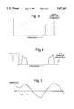
- FIGS. 1a and 1b show how a digital signal may have its sample rate increased by an integer multiple by adding zeros between signal samples in accordance with prior art techniques
- FIGS. 2a and 2b show a typical spectrum of the upsampled signal with images
- FIG. 3 shows the bandpass characteristic of an interpolating filter that will remove the images of the signal shown in FIG. 2b;
- FIG. 4 shows the spectrum of the filtered signal of FIG. 3 with the images removed
- FIG. 5 shows how the interpolating filter smoothes the sampled waveform, calculating the values of intermediate samples
- FIG. 6 shows the impulse response of a filter used to eliminate undesired images
- FIG. 7 shows the frequency response of a filter of FIG. 6 which is useful in understanding the present invention
- FIG. 8 shows a schematic diagram of the interpolating filter
- FIGS. 8a and 8b show increasing the sample rate of a digital signal by replicating the samples in accordance with the principles of the present invention
- FIG. 9 shows the impulse response of the filter of the present invention.
- FIG. 10 shows the frequency response of the filter of the present invention.
- FIG. 11 shows the composite filter frequency response of the filter of the present invention.
- the classical technique of increasing the sample rate of a digital signal by an integer multiple is to insert a number of zeroes after each sample of the signal.
- the approach is shown in FIGS. 1a and 1b.
- the signal sample rate is to be increased by a factor of two, one zero is inserted after each sample.
- the resulting signal spectrum has images of the signal spaced in frequency at distances equal to the original sample rate. Since the new sample rate is at a multiple of the original sample rate, the images constitute unwanted signals in the signal spectrum.
- FIGS. 2a and 2b show a typical spectrum of an upsampled signal with images.
- FIG. 3 shows the bandpass characteristic of a filter that will remove the images of the signal shown in FIG. 2b.
- FIG. 4 shows the spectrum of the filtered signal with the images removed. The effect of the filter in the time domain is shown in FIG. 5. The filter calculates values for intermediate samples between the samples of the original signal, filling in the zeroes of the upsampled signal.
- the digitized signal is represented by a set of integer values depending on the accuracy of the original analog-to-digital converter.
- the signal is quantized with eight bits, ten bits, or twelve bits. Some video converters, for example, use as few as six bits.
- the signal values that can be represented will depend on the number of bits in the signal. For example, an eight bit signal will have values between -128 and +127. A ten bit signal will have values between -512 and +511. A typical representation of the signal value will be a "2s complement" integer.
- FIG. 6 shows the impulse response of a suitable filter that has a flat frequency response over the range from zero to 3700 Hz.
- the frequency response of this filter is shown in FIG. 7.
- the impulse response has values that are integers at the sample points and that may be represented as eight bit numbers.
- a number is formed that has a number of bits that is equal to the sum of the number of bits in the number and the number of bits in the coefficient.
- the numbers are divided by a selected integer and the fractional part is discarded by rounding the result. Rounding of the coefficients to form integers for the filter implementation limits the performance of the filter.
- performance is improved when interpolation is performed by replicating each sample instead of inserting zeroes.
- a different filter is required to compensate for the different implementation of the interpolation process.
- the replication of samples using the present invention is easier to perform compared to inserting zeroes.
- FIG. 8 shows a schematic diagram of the interpolating filter 10.
- FIGS. 8a and 8b illustrate the technique that is used to increase the sample rate in accordance with the principles of the present invention.
- the interpolating filter 10 is used to interpolate to a sample rate that is higher than an input sample rate of the digital input signal.
- the interpolating filter 10 includes replicating means 11 comprising a sample and hold circuit 11 for sampling the digital input signal and replicating it digitally a predetermined number of times to increase the sample rate by an integer. This produces replicated samples of the input signal.
- a smoothing filter 12 is coupled to the replicating means 11 (sample and hold circuit 11) for receiving the replicated samples.
- the smoothing filter 12 has a shape with a high frequency enhancement followed by a sharp cutoff that compensates for the replicated samples of the signal.
- the smoothing filter 12 providing interpolated digital output signals therefrom that are at a sample rate higher than the input sample rate.
- Each sample of the digital input signal is replicated a requisite number of times, instead of inserting zeroes. This has the effect of producing a digital "sample and hold" of the signal.
- the sampled signal changes in steps instead of comprising a collection of pulses.
- filtering theory it is known that a sample and hold or boxcar filter has a sin(x/x) frequency response. The response rolls off at higher frequencies, distorting the shape of the signal.
- the roll-off of the sin x/x filter may be corrected.
- the same performance in the passband may be achieved as for the conventional filter that processes the signal with inserted zero value samples.
- the performance of the filter 10 in the stop band is considerably improved.
- the present filter 10 with replicated samples is easier to build, since the circuits that perform the sample and hold operation are much simpler than circuits that insert zeroes.
- FIG. 9 shows the impulse response of a filter 10 that may be used to interpolate a signal to increase the sample rate by a factor of four.
- the frequency response of the filter 10 of FIG. 9 is shown in FIG. 10.
- the sample rate is 8000 samples per second.
- the signal is a telephone voice signal with a passband from 300 to 3700 Hz with the signal down by 40 dB at 4000 Hz, suitable for digitization at 8000 samples per second.
- the interpolating filter 10 is a low pass filter that is flat +0.2 dB to 3700 Hz. The filter rolls off to more than 40 dB down by 4300 Hz for the interpolated signal in order to eliminate the image that appears at 4300 Hz.
- the effect of replicating the Samples four times instead of inserting three zeroes is to increase the energy in the signal that is filtered by a factor of four.
- a factor of four provides a total of 12 dB greater effective signal power.
- the sidelobe level of the filter has not changed. The result is that the present filtering technique has increased the image rejection power of the filter 10 by 12 dB over an implementation that uses inserted zeroes.
- the interpolation filter 10 may be generated using well-known techniques available from several sources.
- the filters 10 used as examples herein were generated using techniques described in a book by T. W. Parks and C. S. Burrus, entitled “Digital Filter Design", John Wiley and Sons, Inc. New York, 1987.
- the filters described in the present specification are low pass filters 10, but the present technique is equally applicable to bandpass filters 10, or to filters 10 of any arbitrary shape.
- the filters 10 need only be tilted up at the high frequency end of the spectrum to account for the roll-off due to the replication of the samples.
- the present interpolating filter 10 and technique is useful in the implementation of a system where signals at a number of different sample frequencies are to be resampled at a single frequency for output through a digital-to-analog converter. It is useful, but not required, for the sample frequency (rate) to be a power of two different from the output sample frequency (rate). Any integer ratio between the input sample frequency and the output sample frequency may be used. As is traditionally done in the digital signal domain, an artificial sample frequency may be used that is an integer multiple of both the input sample rate and the output sample rate. In this situation, the output samples are calculated only at the samples of the output sample rate, eliminating the samples at the artificial sample rate that are not needed at the output. In this manner, a signal may be upsampled to a sample rate that is not a simple integer multiple of the input sample rate.
Landscapes
- Physics & Mathematics (AREA)
- Engineering & Computer Science (AREA)
- General Physics & Mathematics (AREA)
- Mathematical Analysis (AREA)
- Mathematical Optimization (AREA)
- Pure & Applied Mathematics (AREA)
- Computational Mathematics (AREA)
- Data Mining & Analysis (AREA)
- Mathematical Physics (AREA)
- Theoretical Computer Science (AREA)
- Algebra (AREA)
- Databases & Information Systems (AREA)
- Software Systems (AREA)
- General Engineering & Computer Science (AREA)
- Analogue/Digital Conversion (AREA)
Abstract
Description
Claims (5)
Priority Applications (1)
| Application Number | Priority Date | Filing Date | Title |
|---|---|---|---|
| US08/422,892 US5657261A (en) | 1995-04-17 | 1995-04-17 | Interpolation of digital signals using signal sample replication |
Applications Claiming Priority (1)
| Application Number | Priority Date | Filing Date | Title |
|---|---|---|---|
| US08/422,892 US5657261A (en) | 1995-04-17 | 1995-04-17 | Interpolation of digital signals using signal sample replication |
Publications (1)
| Publication Number | Publication Date |
|---|---|
| US5657261A true US5657261A (en) | 1997-08-12 |
Family
ID=23676847
Family Applications (1)
| Application Number | Title | Priority Date | Filing Date |
|---|---|---|---|
| US08/422,892 Expired - Lifetime US5657261A (en) | 1995-04-17 | 1995-04-17 | Interpolation of digital signals using signal sample replication |
Country Status (1)
| Country | Link |
|---|---|
| US (1) | US5657261A (en) |
Cited By (12)
| Publication number | Priority date | Publication date | Assignee | Title |
|---|---|---|---|---|
| US6337645B1 (en) * | 1999-03-23 | 2002-01-08 | Microsoft Corporation | Filter for digital-to-analog converters |
| US20020012389A1 (en) * | 2000-05-24 | 2002-01-31 | Jens Wildhagen | Digital filter for IQ-generation, noise shaping and neighbour channel suppression |
| US20030071825A1 (en) * | 2001-10-11 | 2003-04-17 | Sony Computer Entertainment Inc. | Image rendering method |
| US20030118134A1 (en) * | 2001-05-09 | 2003-06-26 | Harris Fredric Joel | Non-recursive resampling digital filter structure for demodulating 3G cellular signals |
| US6657950B1 (en) * | 1999-02-19 | 2003-12-02 | Cisco Technology, Inc. | Optimal filtering and upconversion in OFDM systems |
| US20050168360A1 (en) * | 2004-02-02 | 2005-08-04 | Broadcom Corporation | Low-complexity sampling rate conversion method and apparatus for audio processing |
| US20050225460A1 (en) * | 2004-04-08 | 2005-10-13 | Jensen Henrik T | Method of near-unity fractional sampling rate alteration for high fidelity digital audio |
| US20050258993A1 (en) * | 2004-05-07 | 2005-11-24 | Dialog Semiconductor Gmbh | Sample rate adjustment |
| US7158591B2 (en) * | 2001-05-09 | 2007-01-02 | Signum Concept, Inc. | Recursive resampling digital filter structure for demodulating 3G wireless signals |
| US20080063352A1 (en) * | 2006-09-08 | 2008-03-13 | Marko Hahn | Method and apparatus for increasing the resolution of a data sequence |
| US20150219074A1 (en) * | 2012-08-15 | 2015-08-06 | Vestas Wind Systems A/S | Wind power plant control system, wind power plant including wind power plant control system and method of controlling wind power plant |
| US20150316593A1 (en) * | 2013-03-15 | 2015-11-05 | Mitsubishi Electric Corporation | Merging unit which collects information of power system |
Citations (9)
| Publication number | Priority date | Publication date | Assignee | Title |
|---|---|---|---|---|
| US4109110A (en) * | 1975-02-20 | 1978-08-22 | International Standard Electric Corporation | Digital-to-analog converter |
| US4209771A (en) * | 1977-09-30 | 1980-06-24 | Hitachi, Ltd. | Code converting method and system |
| US4270026A (en) * | 1979-11-28 | 1981-05-26 | International Telephone And Telegraph Corporation | Interpolator apparatus for increasing the word rate of a digital signal of the type employed in digital telephone systems |
| US4460890A (en) * | 1982-01-21 | 1984-07-17 | Sony Corporation | Direct digital to digital sampling rate conversion, method and apparatus |
| US4630034A (en) * | 1981-11-27 | 1986-12-16 | Nippon Electric Co., Ltd. | Sampling frequency converting apparatus |
| US4903019A (en) * | 1987-08-31 | 1990-02-20 | Sanyo Electric Co., Ltd. | Sampling frequency converter for converting a lower sampling frequency to a higher sampling frequency and a method therefor |
| US5075880A (en) * | 1988-11-08 | 1991-12-24 | Wadia Digital Corporation | Method and apparatus for time domain interpolation of digital audio signals |
| US5126737A (en) * | 1990-04-16 | 1992-06-30 | Yamaha Corporation | Method for converting a digital signal into another digital signal having a different sampling frequency |
| US5497152A (en) * | 1993-09-13 | 1996-03-05 | Analog Devices, Inc. | Digital-to-digital conversion using non-uniform sample rates |
-
1995
- 1995-04-17 US US08/422,892 patent/US5657261A/en not_active Expired - Lifetime
Patent Citations (9)
| Publication number | Priority date | Publication date | Assignee | Title |
|---|---|---|---|---|
| US4109110A (en) * | 1975-02-20 | 1978-08-22 | International Standard Electric Corporation | Digital-to-analog converter |
| US4209771A (en) * | 1977-09-30 | 1980-06-24 | Hitachi, Ltd. | Code converting method and system |
| US4270026A (en) * | 1979-11-28 | 1981-05-26 | International Telephone And Telegraph Corporation | Interpolator apparatus for increasing the word rate of a digital signal of the type employed in digital telephone systems |
| US4630034A (en) * | 1981-11-27 | 1986-12-16 | Nippon Electric Co., Ltd. | Sampling frequency converting apparatus |
| US4460890A (en) * | 1982-01-21 | 1984-07-17 | Sony Corporation | Direct digital to digital sampling rate conversion, method and apparatus |
| US4903019A (en) * | 1987-08-31 | 1990-02-20 | Sanyo Electric Co., Ltd. | Sampling frequency converter for converting a lower sampling frequency to a higher sampling frequency and a method therefor |
| US5075880A (en) * | 1988-11-08 | 1991-12-24 | Wadia Digital Corporation | Method and apparatus for time domain interpolation of digital audio signals |
| US5126737A (en) * | 1990-04-16 | 1992-06-30 | Yamaha Corporation | Method for converting a digital signal into another digital signal having a different sampling frequency |
| US5497152A (en) * | 1993-09-13 | 1996-03-05 | Analog Devices, Inc. | Digital-to-digital conversion using non-uniform sample rates |
Cited By (24)
| Publication number | Priority date | Publication date | Assignee | Title |
|---|---|---|---|---|
| US6657950B1 (en) * | 1999-02-19 | 2003-12-02 | Cisco Technology, Inc. | Optimal filtering and upconversion in OFDM systems |
| US6337645B1 (en) * | 1999-03-23 | 2002-01-08 | Microsoft Corporation | Filter for digital-to-analog converters |
| US20020012389A1 (en) * | 2000-05-24 | 2002-01-31 | Jens Wildhagen | Digital filter for IQ-generation, noise shaping and neighbour channel suppression |
| US7161979B2 (en) * | 2000-05-24 | 2007-01-09 | Sony Deutschland Gmbh | Digital filter for IQ-generation, noise shaping and neighbor channel suppression |
| US20030118134A1 (en) * | 2001-05-09 | 2003-06-26 | Harris Fredric Joel | Non-recursive resampling digital filter structure for demodulating 3G cellular signals |
| US7164741B2 (en) * | 2001-05-09 | 2007-01-16 | Signum Concept, Inc. | Non-recursive resampling digital fir filter structure for demodulating 3G cellular signals |
| US7158591B2 (en) * | 2001-05-09 | 2007-01-02 | Signum Concept, Inc. | Recursive resampling digital filter structure for demodulating 3G wireless signals |
| US7116339B2 (en) * | 2001-10-11 | 2006-10-03 | Sony Computer Entertainment Inc. | Image rendering method using recursive interpolation |
| US20030071825A1 (en) * | 2001-10-11 | 2003-04-17 | Sony Computer Entertainment Inc. | Image rendering method |
| US7378995B2 (en) | 2004-02-02 | 2008-05-27 | Broadcom Corporation | Low-complexity sampling rate conversion method and apparatus for audio processing |
| US20050168360A1 (en) * | 2004-02-02 | 2005-08-04 | Broadcom Corporation | Low-complexity sampling rate conversion method and apparatus for audio processing |
| US7180435B2 (en) * | 2004-02-02 | 2007-02-20 | Broadcom Corporation | Low-complexity sampling rate conversion method and apparatus for audio processing |
| US20070040713A1 (en) * | 2004-02-02 | 2007-02-22 | Broadcom Corporation | Low-complexity sampling rate conversion method and apparatus for audio processing |
| US20050225460A1 (en) * | 2004-04-08 | 2005-10-13 | Jensen Henrik T | Method of near-unity fractional sampling rate alteration for high fidelity digital audio |
| US7102547B2 (en) * | 2004-04-08 | 2006-09-05 | Broadcom Corporation | Method of near-unity fractional sampling rate alteration for high fidelity digital audio |
| US6970111B1 (en) * | 2004-05-07 | 2005-11-29 | Dialog Semiconductor Gmbh | Sample rate adjustment |
| US20050258993A1 (en) * | 2004-05-07 | 2005-11-24 | Dialog Semiconductor Gmbh | Sample rate adjustment |
| US20080063352A1 (en) * | 2006-09-08 | 2008-03-13 | Marko Hahn | Method and apparatus for increasing the resolution of a data sequence |
| DE102006042180A1 (en) * | 2006-09-08 | 2008-03-27 | Micronas Gmbh | Method and device for increasing the resolution of a data sequence |
| US8019172B2 (en) | 2006-09-08 | 2011-09-13 | Trident Microsystems (Far East) Ltd. | Method and apparatus for increasing the resolution of a data sequence |
| US20150219074A1 (en) * | 2012-08-15 | 2015-08-06 | Vestas Wind Systems A/S | Wind power plant control system, wind power plant including wind power plant control system and method of controlling wind power plant |
| US9822765B2 (en) * | 2012-08-15 | 2017-11-21 | Vestas Wind Systems A/S | Wind power plant control system |
| US20150316593A1 (en) * | 2013-03-15 | 2015-11-05 | Mitsubishi Electric Corporation | Merging unit which collects information of power system |
| EP2975415A4 (en) * | 2013-03-15 | 2016-11-09 | Mitsubishi Electric Corp | MERGER UNIT FOR COLLECTING ELECTRICAL NETWORK INFORMATION |
Similar Documents
| Publication | Publication Date | Title |
|---|---|---|
| US5432511A (en) | Sampling frequency conversion using interrupt control | |
| US5657261A (en) | Interpolation of digital signals using signal sample replication | |
| US5225787A (en) | Sampling frequency converter including a sigma-delta modulator | |
| JPH0629786A (en) | Low-accuracy fir filter for digital interpolation | |
| EP0561067A2 (en) | Sample rate converter | |
| JPH0681012B2 (en) | Digital delay device | |
| GB2081047A (en) | Recursive low pass digital filter | |
| US5440503A (en) | Digital filtering circuit operable as a three-stage moving average filter | |
| US4016410A (en) | Signal processor with digital filter and integrating network | |
| US7302459B2 (en) | Method and apparatus for digital sample rate conversion | |
| US5606319A (en) | Method and apparatus for interpolation and noise shaping in a signal converter | |
| US4580128A (en) | Digital signal processing device | |
| EP0512619B1 (en) | Sampling frequency converter | |
| US4689759A (en) | Process and installation for the analysis and retrieval of a sampling and interpolation signal | |
| JPH03297212A (en) | Method for converting sampling frequency of digital signal | |
| US4542369A (en) | Digital-to-analog converting device | |
| US6411238B1 (en) | Digital to analog converter with step voltage generator for smoothing analog output | |
| EP0766386B1 (en) | Apparatus for reducing quantization distortion | |
| US6229464B1 (en) | Pulse code modulated to DC centered VSB converter | |
| JPH0795817B2 (en) | Digital television signal processor with error correction | |
| JP2605284Y2 (en) | Data converter | |
| JPS5898793A (en) | Voice synthesizer | |
| JP2979712B2 (en) | Filter device | |
| US7262717B2 (en) | Sample rate conversion combined with filter | |
| JP2635668B2 (en) | Digital waveform equalizer |
Legal Events
| Date | Code | Title | Description |
|---|---|---|---|
| AS | Assignment |
Owner name: LORAL AEROSPACE CORPORATION, NEW YORK Free format text: ASSIGNMENT OF ASSIGNORS INTEREST;ASSIGNORS:WILSON, DENNIS L.;SMITH, M. CAMPBELL;REEL/FRAME:007459/0168 Effective date: 19950412 |
|
| STCF | Information on status: patent grant |
Free format text: PATENTED CASE |
|
| AS | Assignment |
Owner name: LOCKHEED MARTIN AEROSPACE CORPORATION, MARYLAND Free format text: CHANGE OF NAME;ASSIGNOR:LORAL AEROSPACE CORPORATION;REEL/FRAME:009430/0939 Effective date: 19960429 |
|
| AS | Assignment |
Owner name: LOCKHEED MARTIN CORPORATION, MARYLAND Free format text: MERGER;ASSIGNOR:LOCKHEED MARTIN AEROSPACE CORP.;REEL/FRAME:009833/0831 Effective date: 19970627 |
|
| FEPP | Fee payment procedure |
Free format text: PAYOR NUMBER ASSIGNED (ORIGINAL EVENT CODE: ASPN); ENTITY STATUS OF PATENT OWNER: LARGE ENTITY |
|
| FPAY | Fee payment |
Year of fee payment: 4 |
|
| FPAY | Fee payment |
Year of fee payment: 8 |
|
| FPAY | Fee payment |
Year of fee payment: 12 |
|
| REMI | Maintenance fee reminder mailed |