US5647331A - Liquid cooled fuel pump and vapor separator - Google Patents
Liquid cooled fuel pump and vapor separator Download PDFInfo
- Publication number
- US5647331A US5647331A US08/699,790 US69979096A US5647331A US 5647331 A US5647331 A US 5647331A US 69979096 A US69979096 A US 69979096A US 5647331 A US5647331 A US 5647331A
- Authority
- US
- United States
- Prior art keywords
- fuel
- pump
- sump
- casing
- vapor
- Prior art date
- Legal status (The legal status is an assumption and is not a legal conclusion. Google has not performed a legal analysis and makes no representation as to the accuracy of the status listed.)
- Expired - Lifetime
Links
Images


Classifications
-
- F—MECHANICAL ENGINEERING; LIGHTING; HEATING; WEAPONS; BLASTING
- F02—COMBUSTION ENGINES; HOT-GAS OR COMBUSTION-PRODUCT ENGINE PLANTS
- F02M—SUPPLYING COMBUSTION ENGINES IN GENERAL WITH COMBUSTIBLE MIXTURES OR CONSTITUENTS THEREOF
- F02M37/00—Apparatus or systems for feeding liquid fuel from storage containers to carburettors or fuel-injection apparatus; Arrangements for purifying liquid fuel specially adapted for, or arranged on, internal-combustion engines
- F02M37/04—Feeding by means of driven pumps
- F02M37/08—Feeding by means of driven pumps electrically driven
- F02M37/10—Feeding by means of driven pumps electrically driven submerged in fuel, e.g. in reservoir
-
- F—MECHANICAL ENGINEERING; LIGHTING; HEATING; WEAPONS; BLASTING
- F02—COMBUSTION ENGINES; HOT-GAS OR COMBUSTION-PRODUCT ENGINE PLANTS
- F02M—SUPPLYING COMBUSTION ENGINES IN GENERAL WITH COMBUSTIBLE MIXTURES OR CONSTITUENTS THEREOF
- F02M37/00—Apparatus or systems for feeding liquid fuel from storage containers to carburettors or fuel-injection apparatus; Arrangements for purifying liquid fuel specially adapted for, or arranged on, internal-combustion engines
- F02M37/20—Apparatus or systems for feeding liquid fuel from storage containers to carburettors or fuel-injection apparatus; Arrangements for purifying liquid fuel specially adapted for, or arranged on, internal-combustion engines characterised by means for preventing vapour lock
Definitions
- This invention relates to fuel delivery systems for internal combustion engines, and more particularly to a liquid cooled fuel pump and vapor separator for use with water cooled internal combustion engines.
- an object of the present invention to provide an improved liquid cooled fuel pump, liquid fuel reservoir and vapor separator module incorporating a liquid-to-liquid heat exchanger for the electric fuel pump and reservoir of the module for cooling both incoming tank fuel being fed to the pump and the electric motor and fuel pump contained in the module to thereby inhibit development of pump vapor lock conditions, to provide a fuel sump for collecting a reserve supply of liquid fuel in the module for delivery to the pump inlet, which is also cooled by the aforementioned heat exchange, to provide for separation of vapor from the sump fuel prior to entry to the pump with the vapor being returned to the engine intake manifold, to thereby further inhibit pump vapor lock, and to provide such an module which is economical to manufacture, rugged and reliable in use, which is compatible with a pump outlet bypass pressure regulator incorporated in the module and which has a long and useful service life.
- the invention achieves the aforementioned objects by housing a standard electric fuel pump in an aluminum body module formed by two iso-pods joined open-end-to-open-end to provide a multi-cavity housing of heat conductive material.
- the housing has two side-by-side cavities with their major axes oriented vertically in use.
- the fuel pump is installed inlet end down in one of the cavities and communicates with the pump inlet at the bottom of this cavity.
- a clearance volume surrounds the pump casing which in one embodiment contains liquid fuel and in another embodiment contains cooling water.
- the other housing cavity forms a fuel sump at its lower end and a vapor separator chamber at its upper end.
- Fuel is supplied to the vapor separator/sump cavity pulse from a fuel tank at low pressure (3-8 psi) and enters via a float operated inlet needle valve provided in the vapor separator/sump cavity.
- the fuel collects as a reserve supply within this float reservoir and the sump headspace is maintained at atmospheric pressure, or slightly thereabove.
- Vapor separating from the liquid fuel in the sump into the sump headspace is vented therefrom through a vent passageway controlled by a suitable vapor pressure regulator, this vapor preferably being conducted by a vent conduit to the engine intake manifold.
- An internal casing cross passage connects the bottom of the sump with the pump cavity in the vicinity of the pump inlet. Incoming fuel thus contacts both the fuel pump body and the vapor sump reservoir housing, and in one embodiment, the fuel surrounding the pump assists heat transfer from pump to the housing.
- the module housing is also provided with a water coolant passageway system sealed from the housing fuel containing cavities and surrounding the pump cavity.
- This coolant passageway system is connected to coolant inlet and outlets of the housing for circulation of cooling water through the housing to thereby carry away heat transferred to the housing either by transfer from the fuel in the module and/or by direct immersion of the pump in the coolant.
- the fresh or sea water boat intake normally provided for the engine cooling water is connected in series with the module coolant passageway so as to circulate this cold water therethrough on its way to the inlet of the engine cooling system, and which in turn typically discharges engine cooling water into the boat exhaust system.
- the module coolant liquid can be recirculated through a suitable heat exchanger, such as a radiator for reuse in the module cooling system.
- the module reduces the pump outlet fuel temperature to a temperature only slightly above that of the liquid coolant in the module.
- Fuel cooling can be further enhanced for providing the module with external heat radiating fins to further disperse heat from the unit either when the module is located internally or externally of the fuel tank, and preferably remote from the engine in either event.
- the module is located in a cooling stream between and remote from both the tank and engine.
- FIG. 1 is a simplified semi-diagrammatic illustration of a first embodiment of a liquid cooled fuel pump and vapor separator module as installed in a boat of the inboard-engine, single screw type and operably connected to deliver fuel between the fuel tank and boat engine;
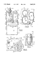
- FIG. 2 is a top plan view of the liquid cooled fuel pump and vapor separator unit shown by itself;
- FIGS. 3 and 4 are vertical cross-sectional views taken respectively on the lines 3--3 and 4--4 of FIG. 2;
- FIG. 4A is a fragmentary cross-sectional view taken on the line 4A--4A of FIG. 4;
- FIG. 5 is a horizontal cross-sectional view taken on the line 5--5 of FIG. 3;
- FIG. 6 is a vertical cross-sectional view taken on the line 6--6 of FIG. 2;
- FIG. 7 is a fragmentary enlarged view of the upper right hand portion of FIG. 4 illustrating in greater detail the vapor pressure regulator associated with the vapor dome of the unit;
- FIG. 8 is a vertical cross-sectional view taken on the line 8--8 of FIG. 2;
- FIG. 9 is a horizontal cross-sectional view taken on the line 9--9 of FIG. 8;
- FIG. 10 is a horizontal cross-sectional view taken on the line 10--10 of FIG. 3;
- FIG. 11 is a fragmentary vertical cross-sectional view taken on the line 11--11 of FIG. 5;
- FIGS. 12 and 13 are vertical side elevational views of the module respectively looking in the direction of the arrows 12 and 13 of FIG. 2;
- FIG. 14 is a bottom plan view of the module
- FIG. 15 is a view similar to FIG. 3 illustrating a second embodiment of the module of the invention.
- FIG. 1 illustrates in simplified semi-diagrammatic form marine application of a first embodiment of a liquid cooled fuel pump and vapor separator unit 20 of the invention in the form of an externally installed module mounted in the hull of a single screw power boat 22 for delivering liquid fuel from a fuel tank 24 of the boat to the fuel injectors of an inboard internal combustion marine engine 26 of the boat.
- Unit 20 is shown in conjunction with a "no-return" type fuel delivery system between and remote from tank 24 and engine 26 and is operable to receive low pressure liquid fuel e.g., gasoline, from tank 24 via a fuel feed line 28 connected between tank 24 and the fuel inlet 90 (FIGS. 4, 4A and 12) of unit 20.
- a "no-return" type fuel delivery system between and remote from tank 24 and engine 26 and is operable to receive low pressure liquid fuel e.g., gasoline, from tank 24 via a fuel feed line 28 connected between tank 24 and the fuel inlet 90 (FIGS. 4, 4A and 12) of unit 20.
- Unit 20 is operable to feed high pressure liquid fuel via a fuel delivery line 30 connected at its inlet to a fuel outlet 66 (FIG. 3) of unit 20 and connected at its downstream outlet to a conventional fuel rail 32 feeding conventional fuel injectors of engine 26.
- a standard diaphragm operated fuel pump (not shown) is mounted on engine 26 and is operably coupled between tank 24 and line 28 to pump tank fuel under low pressure (e.g., 3-8 psi) via line 28 to the inlet of unit 20.
- unit 20 comprises an aluminum die cast iso-pod type multi-cavity housing made of an upper casing 40 and a lower casing 42 fastened together at the mid-plane of the housing by a peripheral array of machine screws or bolts 44, 46.
- Casings 40 and 42 are generally die-cast aluminum hollow half shells formed with chambers and passages opening at their mutually facing ends and closed at the axially opposite ends to provide a sealed iso-pod housing as assembled in FIGS. 2-14.
- Suitable O-ring seals 48, 50, 52 are provided in grooves in the upper face of the lower casing part 42 and clamped by the facing edge of upper casing 40 in assembly of unit 20.
- Unit 20 includes a high pressure fuel pump 54 which is preferably a commercially available in-tank fuel pump as manufactured and sold by the Walbro Corporation, assignee of record herein.
- Pump 54 may be either a turbine type pump or a positive displacement type pump.
- a suitable positive displacement gear rotor type fuel pump is disclosed in U.S. Pat. No. 4,697,995, and a suitable turbine regenerative fuel pump is disclosed in U.S. Pat. No. 5,257,216, the disclosures of which are incorporated herein by reference, and hence pump 54 will not be described in further detail.
- an outlet nipple 56 of pump 54 is coupled by a resilient sleeve 58 to the bore 60 of a hollow casing boss 62 which, via a connecting passage 64, communicates with the threaded inlet coupling fitting (not shown) of fuel line 30 threadably received in the threaded passage of outlet 66 of upper casing 40.
- a conventional hermatically sealed electrical terminal connector fitting 67 is provided in the upper end of pump housing 69 for coupling external power and control leads to internal motor power and control leads.
- Pump 54 is received with a relatively large side clearance in a cylindrical cavity bore 68 conjointly formed by a pump housing portion 69 of upper casing part 40 and a pump housing portion 71 of lower casing part 42.
- the portion of bore 68 that is formed in housing portion 71 of lower casing 42 has at least three circumferentially spaced and axially extending and radially inwardly protruding mounting ribs (not shown) for telescopingly receiving the casing of pump 54 with a press fit in the ribs to thereby mount pump 54 for suspension in bore 68 with a surrounding radial clearance space 170 shown in FIGS. 3 and 6.
- Unit 20 also has a kidney-shaped fuel well or sump chamber 70 (FIG. 5) formed by a cup-like cavity 72 in lower casing 42.
- cavity 72 communicates at its upper open end with the open lower ends of a vapor separator cavity 74 and a fuel return chamber cavity 76 respectively provided in side-by-side towers 78 and 80 formed on upper casing part 40.
- Cavity 74 defines a fuel return and vapor separator chamber 82 and cavity 76 defines a vapor separator and vapor outlet chamber 84.
- Liquid fuel is supplied to fuel sump 70 of unit 20 via tank feed line 28 which is coupled at its outlet end to a hose nipple 90 (FIGS. 4 and 4A) of an inlet fitting 91 threadably mounted in an interior boss 92 of upper casing 40.
- Fuel is admired to sump 70 under the control of an inlet needle valve 94 operated through a lever arm 96 pivoted by a pin 98 on the lower end of boss 92 (FIG. 4A).
- Lever arm 96 is fixed at its pin-remote end to a kidney-shaped float 100 which maintains needle valve 94 closed when the fuel level 102 reaches the elevation shown in FIGS. 3, 4, 8 and 12.
- upper casing tower 80 provides for sump vapor collection in chamber 84 which is open at its lower end to the head space of sump 70 in lower casing 42.
- a pair of suitable perforated, kidney-shaped splash baffles 106 and 108 may be mounted in the lower ends of cavities 82 and 84 to serve as perforate covers over sump 70 to impede upward splashing of liquid fuel from sump 70 into chambers 82 and 84.
- the upper end of chamber 84 communicates via a passage 110 with the regulating chamber 112 of a conventional diaphragm-type vapor pressure regulator unit 114 mounted on the upper end of tower 80 (FIGS. 4 and 7).
- a diaphragm 116 carries a valve 118 which opens and closes a vent passage 120 in turn coupled by an outlet hose nipple 122 to a suitable fuel vapor vent line typically leading to an intake port in the intake manifold of engine 26.
- the upper diaphragm chamber 124 of regulator 114 contains a spring 126 for biasing diaphragm 116 and associated valve 118 towards closed position, and chamber 124 is coupled by a vent 128 to ambient atmosphere.
- the companion upper casing tower 78 has mounted on its upper end a conventional diaphragm-operated fuel by-pass type pressure regulator 130 having its inlet communicated (in the case of a no-return systems) by a cross passage 132 to the outlet passage 64 from pump 54.
- Unit 20 is then operable in the manner of a "no-return" type fuel delivery system to thereby provide pressure regulation of fuel in delivery line 30 by engine by-pass of pump fuel output flowing via by-pass passage 132 through regulator 130 and into an interior by-pass return tube 134 extending downwardly in chamber 82 (FIGS. 3 and 8).
- pump 54 supplies a greater quantity of fuel to pressure regulator 130 than is needed to meet the operational demand of operating engine 26.
- Regulator 130 maintains a substantially constant pressure of fuel supplied through the fuel delivery line 30 to the fuel rail 32 of engine 26, and by-passes or discharges excess fuel through its outlet tube 134 into the reservoir sump 70.
- the pressure regulator will maintain a substantially constant output pressure in line 30, such as 50 psi, with a pressure drop of about 1 psi over the full range of variation of the fuel flow rate to the engine from say 0 to 40 gallons per hour.
- Regulator 130 has a nipple 131 for connecting its spring/diaphragm regulating chamber with either ambient atmosphere, the engine intake manifold or engine exhaust manifold.
- Suitable pressure regulators for such no-return fuel systems are disclosed in U.S. Pat. No. 5,220,941 and 5,398,655, the disclosures of which are incorporated herein by reference and not described in greater detail.
- a Schrader valve 140 may also be mounted to the top of casing 40 for checking pump outlet pressure and for bleeding the system lines after a dormant period (e.g., winter lay up of boat 22).
- unit 20 is also readily converted for use in a "return-type" fuel delivery system wherein by-pass return fuel is fed from fuel rail 32 through a suitable return line (not shown) to a fuel return inlet passageway 142 (FIGS. 2 and 12) machined in a boss 143 at the upper end of tower 78.
- Passageway 142 feeds fuel from the fuel return line outlet into the regulating valve chamber of regulator 130 for discharge therefrom via tube 134 into sump 70.
- unit 20 also has a hose nipple 144 communicating with an oil drain return tube 146 extending downwardly in vapor chamber 82, through baffle 108, and opening above baffle 106 for returning oil or a fuel and oil mixture from the crankcase of engine 26 in the case of a two-stroke cycle engine using an oil-gasoline fuel mix.
- unit 20 is liquid cooled by utilizing fresh intake cooling water supplied from an existing conventional on-board engine water cooling system as typically provided in boat 22.
- the cooling water feed and return conduits (not shown) for intercoupling the water cooling passageways of unit 20 serially into the intake side of this on-board engine water cooling system are suitably coupled by threaded end fittings (not shown) to lower casing part 42 via inlet and outlet threaded port bosses 150 and 152 respectively (FIGS. 2, 3, 5 and 13).
- threaded end fittings not shown
- the upper and lower casings 40 and 42 are each provided with water cooling passageways in the form of circulation chambers 160 and 162 respectively which in this first embodiment only encircle the outer surfaces of walls 164 and 166 of the pump housing 69.
- the interior surfaces of walls 164 and 166 define the pump cavity 68 in the upper and lower casings 40 and 42.
- the configuration of the water cooling chambers 160 and 162 is shown to scale in FIGS. 3, 4, 5, 6, 9 and 10. It will be seen that this conjoint water cooling chamber circulates intake fresh or sea cold water around wall 166 on its outer side, and such cooling water is also in contact with the side wall 168 of lower casing 42 forming the one side surface of the fuel sump 70.
- the cooling water is shown by broken dash lines in the casing cooling chambers in these views.
- incoming cold water from casing inlet 150 flows in channels 160 and 162 around and adjacent the pump housing walls 164 and 166 in the arrow flow path and exits channels 160 and 162 at casing outlet 152.
- a dam pin or fib 180 is provided in channels 160 and 162 between the pump housing wall and the surrounding casing exterior wall defining such channels to prevent short circuiting flow of cooling water between inlet 150 and outlet 152.
- a standard electric fuel pump 54 is housed in a highly heat conductive aluminum body by two iso-pod casings 40 and 42.
- the small clearance volume space 170 in the pump housing directly surrounds the body of fuel pump 54 and is filled to level 102 with liquid fuel from sump 70 within the lower casing part 42.
- liquid fuel is supplied to unit 20 down through the sump head space to collect in the liquid fuel sump 70 of the vapor separator portion of the casing by the aforementioned engine crankcase pulse-driven diaphragm pump mounted on engine 26 (not shown).
- This engine pump operates to draw liquid fuel from tank 24 and slightly pressurize (3-8 psi) this fuel for supply via fuel line 28 to the inlet needle valve 94 of the vapor separator. After passing through the inlet needle valve 94, the liquid fuel resides within the float reservoir 70 at atmospheric pressure or slightly thereabove.
- Fuel pump 54 is preferably mounted such that its inlet fitting 105 (containing a conventional fuel filter element) is directed downwardly into its own chamber well 172 at the bottom of pump housing 71 of casing part 42.
- Liquid fuel is able to pass from sump 70 through casing passage 104 into chamber 172 and up around the clearance space 170 surrounding the casing of pump 54 to thereby bath the exterior of the lower end of pump 54 with such liquid fuel.
- Liquid fuel in sump 70 also contacts and flows against the heat conductive casing walls, such as wall 168 of casing 42 partially defining fuel reservoir sump 70.
- liquid fuel is able to absorb heat from the pump and retransmit it both to the ambient air cooled aluminum exterior walls of lower casing part 42 and to the interior water cooled pump housing walls.
- casing water cooling channels 160 and 162 are isolated from the fuel chambers and fuel passageways in this first embodiment by the aluminum walls of casing parts 40 and 42, these channels are in close heat exchange proximity through these heat conductive casing walls with the outside of the pump housing clearance volume 170 containing the liquid fuel.
- the liquid cooling water thus can carry away heat transmitted through the aluminum walls of the casing that was transferred to the vapor reservoir and from around the pump casing by the liquid fuel, as well as by radiation into the casing walls from the pump.
- This cooling liquid preferably from the fresh or sea water intake of boat 22, can be either disposed of by discharge into the engine cooling system as described hereinabove, or cooled and recirculated into unit 20 by an on-board conventional heat exchanger system installed on boat 22 (not shown).
- the invention provides a fuel delivery system with a compact unit 20 providing built-in fuel pump and associated fuel vapor separator to both cool the pump as well as the liquid fuel contained in the unit with a built-in liquid coolant system.
- Unit 20 is thus operable to reduce the quantity of fuel vapor generated above the liquid fuel level 102 in the head space of the reservoir 70 and in the vapor domes 82 and 84 communicating with one another via the reservoir head space.
- the vapor pressure regulator 114 may be set to maintain a slightly super-atmospheric pressure in vapor chambers 82, 84 and in the head space of sump 70 to help force fuel toward pump 54.
- vapor separator chamber 84 in conjunction with the liquid cooling system of unit 20, thus operate to eliminate or greatly reduce vapor lock of pump 54 during operation thereof when running to supply fuel to engine 26 and/or by-pass fuel from the pump back to the vapor separator chambers of unit 20.
- Unit 20 is also operable in the manner of an in-tank fuel canister often employed in fuel delivery systems for fuel-injector-equipped engines, i.e., sump 70 contains a reserve quantity of fuel so pump inlet 105 is not momentarily starved by the effects of adverse bodily shaping of the tank fuel or by adverse orientation of tank 24 during operation of boat 22, which may cause intermittent fuel starving of the in-tank inlet of fuel line 28 in tank 24.
- sump 70 contains a reserve quantity of fuel so pump inlet 105 is not momentarily starved by the effects of adverse bodily shaping of the tank fuel or by adverse orientation of tank 24 during operation of boat 22, which may cause intermittent fuel starving of the in-tank inlet of fuel line 28 in tank 24.
- the module unit 20 can take advantage of an unlimited supply of fresh or sea cooling water normally ingested by a boat scupper intake to the engine water pump for circulation through the engine cooling system and then discharged back to the surrounding body of water through the engine exhaust.
- This relatively low temperature water coolant passing through the unit 20 on the intake side of the engine water cooling system can provide a marked reduction in temperature of the liquid fuel supply delivered to the engine fuel intake system. For example, in one test a reduction of 70° F. was achieved in the pump outlet fuel temperature when providing a non-recirculated water supply at a temperature of approximately 57° F. thereby indicating a possible 13° F. temperature difference between the cooling water supply and the pump outlet fuel temperature.
- the module inlet and outlets can be serially connected in the discharge side of the engine cooling radiator for heat transfer from the module to this radiator cooled water prior to its passage to the intake of the engine cooling system.
- the unit being made of die cast aluminum, can be readily provided with suitable cooling fins (not shown) and installed in a location remote from the engine and close to a favorable air cooling source, e.g., for example being close to the vicinity to the engine radiator fan or, in a marine application, close to the outlet of an ambient air intake vent blower to further enhance reduction in pump outlet fuel temperature.
- liquid cooled fuel pump, reservoir and vapor separator module of the invention efficiently accomplishes a marked reduction of fuel temperature both within the module sump and in the module pump that greatly inhibits the tendency for the fuel to vaporize, thereby reducing vapor lock problems in both the fuel pump and in the fuel delivery system to the fuel injectors of the engine.
- FIG. 15 illustrates a second embodiment of a module 20' of the invention wherein elements identical to those previously described are given like reference numerals, and wherein slightly modified elements are given like reference numerals having a prime suffix, and the description of such elements is not repeated.
- module 20'0 is similar to module 20 except that the mast of the exterior surface of the casing of pump 54 is directly immersed in the cooling water, rather than in the fuel being fed to the pump inlet, as in module 20, wherein the pump is separated from cooling water by the fuel in clearance space 170 and by the cooling passageway water jacket walls.
- a circumferentially spaced annular row of a plurality of vertically elongated large area flow openings two of such openings 200 and 202 being seen in FIG. 15, are provided in wall 166 of pump housing 71 of lower casing port 42, the cooling water passageway system of module 20' thus now additionally includes the annular clearance volume channel 160' directly exposed to and surrounding volume mast of the axial extent of the pump casing.
- Channel 160' is sealed at its upper and lower ends by suitable resilient sealing grommets 204 and 206 respectively encircling the upper and lower ends of the major diameter main body portion of the casing of pump 54, that portion of bore 68 formed in upper casing part 40' has a counterbore 208 formed at its lower end to telescopically receive upper grommet 204 so as to seat against an annular stop shoulder 210.
- a similar counterbore 212 and associated shoulder 214 is provided in that portion of bore 68 formed in lower casing part 42' to thereby likewise receive and seat lower grommet 206.
Landscapes
- Engineering & Computer Science (AREA)
- Chemical & Material Sciences (AREA)
- Combustion & Propulsion (AREA)
- Mechanical Engineering (AREA)
- General Engineering & Computer Science (AREA)
- Fuel-Injection Apparatus (AREA)
Abstract
Description
Claims (13)
Priority Applications (1)
| Application Number | Priority Date | Filing Date | Title |
|---|---|---|---|
| US08/699,790 US5647331A (en) | 1995-09-12 | 1996-08-19 | Liquid cooled fuel pump and vapor separator |
Applications Claiming Priority (2)
| Application Number | Priority Date | Filing Date | Title |
|---|---|---|---|
| US358395P | 1995-09-12 | 1995-09-12 | |
| US08/699,790 US5647331A (en) | 1995-09-12 | 1996-08-19 | Liquid cooled fuel pump and vapor separator |
Publications (1)
| Publication Number | Publication Date |
|---|---|
| US5647331A true US5647331A (en) | 1997-07-15 |
Family
ID=21706563
Family Applications (1)
| Application Number | Title | Priority Date | Filing Date |
|---|---|---|---|
| US08/699,790 Expired - Lifetime US5647331A (en) | 1995-09-12 | 1996-08-19 | Liquid cooled fuel pump and vapor separator |
Country Status (2)
| Country | Link |
|---|---|
| US (1) | US5647331A (en) |
| JP (1) | JP3828616B2 (en) |
Cited By (49)
| Publication number | Priority date | Publication date | Assignee | Title |
|---|---|---|---|---|
| US5865160A (en) * | 1996-05-23 | 1999-02-02 | Sanshin Kogyo Kabushiki Kaisha | Fuel supply system for outboard motor |
| WO1999006689A1 (en) * | 1997-08-01 | 1999-02-11 | Ford Global Technologies, Inc. | Fuel vapour extraction system |
| US5881698A (en) * | 1997-12-01 | 1999-03-16 | Walbro Corporation | Fuel pump with regulated output |
| US5887555A (en) * | 1998-06-23 | 1999-03-30 | Thermo Power Corporation | Cooling device for a fuel pump and fuel in a marine combustion engine |
| US5908020A (en) * | 1998-07-13 | 1999-06-01 | Uis, Inc. | Marine fuel pump and cooling system |
| US6009859A (en) * | 1997-12-08 | 2000-01-04 | Walbro Corporation | Liquid-cooled in-line fuel pump |
| US6012434A (en) * | 1998-07-20 | 2000-01-11 | Outboard Marine Corporation | Fuel system vapor separator for an internal combustion engine |
| WO2000068562A1 (en) * | 1999-05-10 | 2000-11-16 | Federal-Mogul Corporation | Water cooled electric fuel pump for marine propulsion |
| US6149399A (en) * | 1998-12-21 | 2000-11-21 | Ford Global Technologies, Inc. | Fuel tank dual fuel delivery module |
| US6216672B1 (en) * | 1998-06-29 | 2001-04-17 | Suzuki Kabushiki Kaisha | Fuel supply system of outboard motor |
| US6240904B1 (en) | 2000-06-13 | 2001-06-05 | Uis, Inc. | Stand alone multi stage fuel pump |
| US6257208B1 (en) | 1999-08-17 | 2001-07-10 | Federal-Mogul World Wide, Inc. | Marine-vapor separator |
| WO2001079683A1 (en) * | 2000-04-18 | 2001-10-25 | Uis Inc. | Integrated fuel system unit with two-stage marine fuel pump |
| WO2002004804A1 (en) * | 2000-07-06 | 2002-01-17 | Bombardier Motor Corporation Of America | Dead-headed fuel delivery system using a single fuel pump |
| WO2001040638A3 (en) * | 1999-12-01 | 2002-01-17 | Bosch Gmbh Robert | Fuel supply system for an internal combustion engine |
| US6422207B1 (en) * | 2000-11-28 | 2002-07-23 | Bombardier Motor Corporation Of America | Fuel vapor separator |
| EP1164281A3 (en) * | 2000-06-16 | 2002-10-30 | Siemens Aktiengesellschaft | Device for pumping fuel and ventilating the fuel tank |
| US6575145B2 (en) * | 2000-11-27 | 2003-06-10 | Yamaha Marine Kabushiki Kaisha | Fuel supply system for four-cycle outboard motor |
| US6588449B1 (en) | 2000-08-31 | 2003-07-08 | Saturn Electronics & Engineering, Inc. | Diesel fuel shut-off device |
| US20040003796A1 (en) * | 2002-07-05 | 2004-01-08 | Keihin Corporation | Fuel injection apparatus for marine engine |
| US6679229B2 (en) * | 2001-05-14 | 2004-01-20 | Honda Giken Kogyo Kabushiki Kaisha | Fuel supply apparatus in outboard engine |
| US6718953B1 (en) | 2002-07-19 | 2004-04-13 | Brunswick Corporation | Fuel vapor separator with a flow directing component within a fuel recirculating flow path |
| US6857419B1 (en) * | 2004-04-06 | 2005-02-22 | Federal-Mogul World Wide, Inc. | Fuel vapor separator for internal combustion engine |
| US6866029B1 (en) * | 2002-10-25 | 2005-03-15 | Brunswick Corporation | Marine vessel fuel system with a fuel pump attached to an external surface of a fuel tank |
| US20050263141A1 (en) * | 2004-05-25 | 2005-12-01 | Honda Motor Co., Ltd. | Vehicle fuel supply construction |
| US20060048757A1 (en) * | 2004-09-03 | 2006-03-09 | Federal-Mogul World Wide, Inc. | Marine vapor separator with bypass line |
| US7013878B1 (en) | 2004-06-03 | 2006-03-21 | Walbro Engine Management, L.L.C. | Fuel vapor separator |
| US20060144371A1 (en) * | 2005-01-03 | 2006-07-06 | Kwang Yang Motor Co., Ltd. | Gas filtering and recirculating device for general machine |
| US20070101974A1 (en) * | 2005-10-14 | 2007-05-10 | Achor Kyle D | Marine fuel vapor separator with vent control device |
| US20070186976A1 (en) * | 2006-02-16 | 2007-08-16 | Ti Group Automotive Systems, L.L.C. | Fuel storage system for a vehicle |
| US7278408B1 (en) * | 2005-11-30 | 2007-10-09 | Brunswick Corporation | Returnless fuel system module |
| US20080041464A1 (en) * | 2006-08-16 | 2008-02-21 | Honda Motor Co., Ltd. | Fuel supply system for general purpose engine |
| US20080060618A1 (en) * | 2006-09-12 | 2008-03-13 | Mikuni Corporation | Vapor separator tank |
| US7431021B1 (en) | 2007-09-19 | 2008-10-07 | Federal - Mogul World Wide, Inc. | Fuel vapor separator |
| US20090071448A1 (en) * | 2007-03-21 | 2009-03-19 | Walbro Engine Management, L.L.C | Vapor separator |
| US20090194074A1 (en) * | 2008-02-04 | 2009-08-06 | Radue Martin L | Fuel Delivery System for Engine |
| US20090298364A1 (en) * | 2008-05-30 | 2009-12-03 | Yamaha Hatsudoki Kabushiki Kaisha | Fuel supply system for boat and outboard motor |
| US20090293843A1 (en) * | 2008-05-30 | 2009-12-03 | Yamaha Hatsudoki Kabushiki Kaisha | Fuel supply system for boat and outboard motor |
| US7832380B1 (en) | 2009-01-28 | 2010-11-16 | Brunswick Corporation | Marine fuel system with an ullage control device |
| US20120103284A1 (en) * | 2010-11-03 | 2012-05-03 | Federal-Mogul Corporation | Thermoelectric cooled pump |
| WO2013043379A1 (en) | 2011-09-23 | 2013-03-28 | Federal-Mogul Corporation | Marine fuel system with spill control feature |
| US20130206115A1 (en) * | 2012-02-10 | 2013-08-15 | Ford Global Technologies, Llc. | Methods and systems for fuel vapor control |
| US9206777B2 (en) | 2012-10-26 | 2015-12-08 | Edelbrock, Llc | Fuel system conversions for carburetor to electronic fuel injection systems, methods of production thereof |
| US10047661B1 (en) | 2017-02-14 | 2018-08-14 | Brunswick Corporation | Apparatuses and systems for cooling fuel modules for marine engines |
| WO2018160168A1 (en) * | 2017-02-28 | 2018-09-07 | Ab Volvo Penta | Fuel module for engine |
| US20190195377A1 (en) * | 2017-12-22 | 2019-06-27 | Walbro Llc | Float and hinge for a valve |
| US10851719B2 (en) | 2014-05-29 | 2020-12-01 | Cummins Power Generation Ip, Inc. | Systems for supplying fuel to fuel-injected engines in gensets |
| US11002226B2 (en) * | 2017-04-11 | 2021-05-11 | Bayerische Motoren Werke Aktiengesellschaft | Water tank device for an internal combustion engine with water injection |
| CN113847176A (en) * | 2021-08-20 | 2021-12-28 | 重庆平山泰凯化油器有限公司 | External oil pump of motorcycle |
Families Citing this family (3)
| Publication number | Priority date | Publication date | Assignee | Title |
|---|---|---|---|---|
| JP5061043B2 (en) * | 2008-06-25 | 2012-10-31 | ヤマハ発動機株式会社 | Marine fuel supply system and outboard motor |
| KR101603924B1 (en) * | 2009-04-27 | 2016-03-16 | 카터 퓨얼 시스템즈, 엘엘씨 | Marine fuel delivery system with plastic housing and method of construction thereof |
| JP6512914B2 (en) * | 2015-04-17 | 2019-05-15 | 株式会社ニッキ | Retaining member of regulator in fuel supply system |
Citations (6)
| Publication number | Priority date | Publication date | Assignee | Title |
|---|---|---|---|---|
| US4697995A (en) * | 1982-07-29 | 1987-10-06 | Walbro Corporation | Rotary positive displacement fuel pump with purge port |
| US5103793A (en) * | 1991-01-15 | 1992-04-14 | Brunswick Corporation | Vapor separator for an internal combustion engine |
| US5257916A (en) * | 1992-11-27 | 1993-11-02 | Walbro Corporation | Regenerative fuel pump |
| US5309885A (en) * | 1992-02-13 | 1994-05-10 | Outboard Marine Corporation | Marine propulsion device including a fuel injected, four-cycle internal combustion engine |
| US5375578A (en) * | 1992-03-05 | 1994-12-27 | Sanshin Kogyo Kabushiki Kaisha | High pressure fuel feeding device for fuel injection engine |
| US5389245A (en) * | 1993-08-10 | 1995-02-14 | Brunswick Corporation | Vapor separating unit for a fuel system |
-
1996
- 1996-08-19 US US08/699,790 patent/US5647331A/en not_active Expired - Lifetime
- 1996-09-09 JP JP23784596A patent/JP3828616B2/en not_active Expired - Fee Related
Patent Citations (6)
| Publication number | Priority date | Publication date | Assignee | Title |
|---|---|---|---|---|
| US4697995A (en) * | 1982-07-29 | 1987-10-06 | Walbro Corporation | Rotary positive displacement fuel pump with purge port |
| US5103793A (en) * | 1991-01-15 | 1992-04-14 | Brunswick Corporation | Vapor separator for an internal combustion engine |
| US5309885A (en) * | 1992-02-13 | 1994-05-10 | Outboard Marine Corporation | Marine propulsion device including a fuel injected, four-cycle internal combustion engine |
| US5375578A (en) * | 1992-03-05 | 1994-12-27 | Sanshin Kogyo Kabushiki Kaisha | High pressure fuel feeding device for fuel injection engine |
| US5257916A (en) * | 1992-11-27 | 1993-11-02 | Walbro Corporation | Regenerative fuel pump |
| US5389245A (en) * | 1993-08-10 | 1995-02-14 | Brunswick Corporation | Vapor separating unit for a fuel system |
Cited By (73)
| Publication number | Priority date | Publication date | Assignee | Title |
|---|---|---|---|---|
| US5865160A (en) * | 1996-05-23 | 1999-02-02 | Sanshin Kogyo Kabushiki Kaisha | Fuel supply system for outboard motor |
| WO1999006689A1 (en) * | 1997-08-01 | 1999-02-11 | Ford Global Technologies, Inc. | Fuel vapour extraction system |
| US5881698A (en) * | 1997-12-01 | 1999-03-16 | Walbro Corporation | Fuel pump with regulated output |
| US6009859A (en) * | 1997-12-08 | 2000-01-04 | Walbro Corporation | Liquid-cooled in-line fuel pump |
| US5887555A (en) * | 1998-06-23 | 1999-03-30 | Thermo Power Corporation | Cooling device for a fuel pump and fuel in a marine combustion engine |
| US6216672B1 (en) * | 1998-06-29 | 2001-04-17 | Suzuki Kabushiki Kaisha | Fuel supply system of outboard motor |
| WO2000003137A3 (en) * | 1998-07-13 | 2000-04-13 | Uis Inc | Marine fuel pump and cooling system |
| US5908020A (en) * | 1998-07-13 | 1999-06-01 | Uis, Inc. | Marine fuel pump and cooling system |
| US6012434A (en) * | 1998-07-20 | 2000-01-11 | Outboard Marine Corporation | Fuel system vapor separator for an internal combustion engine |
| US6149399A (en) * | 1998-12-21 | 2000-11-21 | Ford Global Technologies, Inc. | Fuel tank dual fuel delivery module |
| US6322410B1 (en) | 1999-05-10 | 2001-11-27 | Federal-Mogul World Wide, Inc. | Water cooled electric fuel pump for marine propulsion |
| WO2000068562A1 (en) * | 1999-05-10 | 2000-11-16 | Federal-Mogul Corporation | Water cooled electric fuel pump for marine propulsion |
| US6257208B1 (en) | 1999-08-17 | 2001-07-10 | Federal-Mogul World Wide, Inc. | Marine-vapor separator |
| WO2001040638A3 (en) * | 1999-12-01 | 2002-01-17 | Bosch Gmbh Robert | Fuel supply system for an internal combustion engine |
| US6840219B2 (en) * | 1999-12-01 | 2005-01-11 | Robert Bosch Gmbh | Fuel supply system for an internal combustion engine |
| WO2001079683A1 (en) * | 2000-04-18 | 2001-10-25 | Uis Inc. | Integrated fuel system unit with two-stage marine fuel pump |
| US6397822B1 (en) | 2000-04-18 | 2002-06-04 | Uis, Inc. | Integrated fuel system unit with two-stage marine fuel pump |
| US6240904B1 (en) | 2000-06-13 | 2001-06-05 | Uis, Inc. | Stand alone multi stage fuel pump |
| EP1164281A3 (en) * | 2000-06-16 | 2002-10-30 | Siemens Aktiengesellschaft | Device for pumping fuel and ventilating the fuel tank |
| US6581578B2 (en) | 2000-06-16 | 2003-06-24 | Mannesmann Vdo Ag | Fuel delivery and ventilation system |
| WO2002004804A1 (en) * | 2000-07-06 | 2002-01-17 | Bombardier Motor Corporation Of America | Dead-headed fuel delivery system using a single fuel pump |
| US6588449B1 (en) | 2000-08-31 | 2003-07-08 | Saturn Electronics & Engineering, Inc. | Diesel fuel shut-off device |
| US6575145B2 (en) * | 2000-11-27 | 2003-06-10 | Yamaha Marine Kabushiki Kaisha | Fuel supply system for four-cycle outboard motor |
| US6422207B1 (en) * | 2000-11-28 | 2002-07-23 | Bombardier Motor Corporation Of America | Fuel vapor separator |
| WO2002057614A3 (en) * | 2000-11-28 | 2003-06-12 | Bombardier Motor Corp Of Us | Fuel vapor separator |
| US6679229B2 (en) * | 2001-05-14 | 2004-01-20 | Honda Giken Kogyo Kabushiki Kaisha | Fuel supply apparatus in outboard engine |
| US20040003796A1 (en) * | 2002-07-05 | 2004-01-08 | Keihin Corporation | Fuel injection apparatus for marine engine |
| US6739318B2 (en) * | 2002-07-05 | 2004-05-25 | Keihin Corporation | Fuel injection apparatus for marine engine |
| US6718953B1 (en) | 2002-07-19 | 2004-04-13 | Brunswick Corporation | Fuel vapor separator with a flow directing component within a fuel recirculating flow path |
| US6866029B1 (en) * | 2002-10-25 | 2005-03-15 | Brunswick Corporation | Marine vessel fuel system with a fuel pump attached to an external surface of a fuel tank |
| US6857419B1 (en) * | 2004-04-06 | 2005-02-22 | Federal-Mogul World Wide, Inc. | Fuel vapor separator for internal combustion engine |
| WO2005100773A1 (en) * | 2004-04-06 | 2005-10-27 | Federal-Mogul Corporation | Fuel vapor separator for internal combustion engine |
| US20050263141A1 (en) * | 2004-05-25 | 2005-12-01 | Honda Motor Co., Ltd. | Vehicle fuel supply construction |
| US7287518B2 (en) * | 2004-05-25 | 2007-10-30 | Honda Motor Co., Ltd. | Vehicle fuel supply construction |
| US7013878B1 (en) | 2004-06-03 | 2006-03-21 | Walbro Engine Management, L.L.C. | Fuel vapor separator |
| US20060048757A1 (en) * | 2004-09-03 | 2006-03-09 | Federal-Mogul World Wide, Inc. | Marine vapor separator with bypass line |
| US7168414B2 (en) * | 2004-09-03 | 2007-01-30 | Federal Mogul World Wide, Inc. | Marine vapor separator with bypass line |
| US20060144371A1 (en) * | 2005-01-03 | 2006-07-06 | Kwang Yang Motor Co., Ltd. | Gas filtering and recirculating device for general machine |
| US7100580B2 (en) * | 2005-01-03 | 2006-09-05 | Kwang Yang Motor Co., Ltd. | Gas filtering and recirculating device for general machine |
| US7503314B2 (en) | 2005-10-14 | 2009-03-17 | Federal-Mogul World Wide, Inc. | Marine fuel vapor separator with vent control device |
| US20070101974A1 (en) * | 2005-10-14 | 2007-05-10 | Achor Kyle D | Marine fuel vapor separator with vent control device |
| US7278408B1 (en) * | 2005-11-30 | 2007-10-09 | Brunswick Corporation | Returnless fuel system module |
| US7520293B2 (en) | 2006-02-16 | 2009-04-21 | Ti Group Automotive Systems, L.L.C. | Fuel storage system for a vehicle |
| US20070186976A1 (en) * | 2006-02-16 | 2007-08-16 | Ti Group Automotive Systems, L.L.C. | Fuel storage system for a vehicle |
| US20080041464A1 (en) * | 2006-08-16 | 2008-02-21 | Honda Motor Co., Ltd. | Fuel supply system for general purpose engine |
| US7757670B2 (en) * | 2006-08-16 | 2010-07-20 | Honda Motor Co., Ltd. | Fuel supply system for general purpose engine |
| US20080060618A1 (en) * | 2006-09-12 | 2008-03-13 | Mikuni Corporation | Vapor separator tank |
| US20090071448A1 (en) * | 2007-03-21 | 2009-03-19 | Walbro Engine Management, L.L.C | Vapor separator |
| US7827970B2 (en) | 2007-03-21 | 2010-11-09 | Walbro Engine Management, L.L.C. | Vapor separator |
| US7431021B1 (en) | 2007-09-19 | 2008-10-07 | Federal - Mogul World Wide, Inc. | Fuel vapor separator |
| WO2009039345A3 (en) * | 2007-09-19 | 2009-05-28 | Federal Mogul Corp | Fuel vapor separator |
| US20090194074A1 (en) * | 2008-02-04 | 2009-08-06 | Radue Martin L | Fuel Delivery System for Engine |
| WO2009099581A1 (en) * | 2008-02-04 | 2009-08-13 | Kohler Co. | Fuel delivery system for engine |
| US7677225B2 (en) * | 2008-02-04 | 2010-03-16 | Kohler Co. | Fuel delivery system for engine |
| US20090298364A1 (en) * | 2008-05-30 | 2009-12-03 | Yamaha Hatsudoki Kabushiki Kaisha | Fuel supply system for boat and outboard motor |
| US20090293843A1 (en) * | 2008-05-30 | 2009-12-03 | Yamaha Hatsudoki Kabushiki Kaisha | Fuel supply system for boat and outboard motor |
| US7931010B2 (en) * | 2008-05-30 | 2011-04-26 | Yamaha Hatsudoki Kabushiki Kaisha | Fuel supply system for boat and outboard motor |
| US8079887B2 (en) * | 2008-05-30 | 2011-12-20 | Yamaha Hatsudoki Kabushiki Kaisha | Fuel supply system for boat and outboard motor |
| US7832380B1 (en) | 2009-01-28 | 2010-11-16 | Brunswick Corporation | Marine fuel system with an ullage control device |
| US20120103284A1 (en) * | 2010-11-03 | 2012-05-03 | Federal-Mogul Corporation | Thermoelectric cooled pump |
| US9234483B2 (en) * | 2010-11-03 | 2016-01-12 | Carter Fuel Systems, Llc | Thermoelectric cooled pump |
| WO2013043379A1 (en) | 2011-09-23 | 2013-03-28 | Federal-Mogul Corporation | Marine fuel system with spill control feature |
| US9151255B2 (en) | 2011-09-23 | 2015-10-06 | Carter Fuel Systems, Llc | Marine fuel system with spill control feature |
| US20130206115A1 (en) * | 2012-02-10 | 2013-08-15 | Ford Global Technologies, Llc. | Methods and systems for fuel vapor control |
| US9739243B2 (en) * | 2012-02-10 | 2017-08-22 | Ford Gloabl Technologies, LLC | Methods and systems for fuel vapor control |
| US9206777B2 (en) | 2012-10-26 | 2015-12-08 | Edelbrock, Llc | Fuel system conversions for carburetor to electronic fuel injection systems, methods of production thereof |
| US10851719B2 (en) | 2014-05-29 | 2020-12-01 | Cummins Power Generation Ip, Inc. | Systems for supplying fuel to fuel-injected engines in gensets |
| US10047661B1 (en) | 2017-02-14 | 2018-08-14 | Brunswick Corporation | Apparatuses and systems for cooling fuel modules for marine engines |
| WO2018160168A1 (en) * | 2017-02-28 | 2018-09-07 | Ab Volvo Penta | Fuel module for engine |
| US11002226B2 (en) * | 2017-04-11 | 2021-05-11 | Bayerische Motoren Werke Aktiengesellschaft | Water tank device for an internal combustion engine with water injection |
| US20190195377A1 (en) * | 2017-12-22 | 2019-06-27 | Walbro Llc | Float and hinge for a valve |
| US11274762B2 (en) * | 2017-12-22 | 2022-03-15 | Walbro Llc | Float and hinge for a valve |
| CN113847176A (en) * | 2021-08-20 | 2021-12-28 | 重庆平山泰凯化油器有限公司 | External oil pump of motorcycle |
Also Published As
| Publication number | Publication date |
|---|---|
| JP3828616B2 (en) | 2006-10-04 |
| JPH09222055A (en) | 1997-08-26 |
Similar Documents
| Publication | Publication Date | Title |
|---|---|---|
| US5647331A (en) | Liquid cooled fuel pump and vapor separator | |
| US6718953B1 (en) | Fuel vapor separator with a flow directing component within a fuel recirculating flow path | |
| US5389245A (en) | Vapor separating unit for a fuel system | |
| US5036822A (en) | Fuel supplying device for vessel propulsion unit | |
| US5797378A (en) | Fuel supply system | |
| US6527603B1 (en) | Fuel delivery system for a marine propulsion device | |
| US5215164A (en) | Lubricating device for four stroke outboard motor | |
| US7832380B1 (en) | Marine fuel system with an ullage control device | |
| US6158975A (en) | Fuel pump module | |
| US4844704A (en) | Fuel pump assembly | |
| US6009859A (en) | Liquid-cooled in-line fuel pump | |
| US3835822A (en) | Cooled fuel pump for internal combustion engines | |
| US6416373B1 (en) | Oil system vent with remote oil reservoir | |
| US5167207A (en) | Two cycle engine for small boat | |
| US7112110B1 (en) | Fuel system container for a marine vessel | |
| US6695659B2 (en) | Oil system with replaceable oil filter for two-cycle engines | |
| US4768580A (en) | Marine propulsion device oil cooling arrangement | |
| US4553585A (en) | Cooling arrangement for internal combustion engines with combined seawater-fresh water cooling | |
| US6422207B1 (en) | Fuel vapor separator | |
| US6428375B2 (en) | Fuel cooling apparatus of outboard motor | |
| US7401598B2 (en) | Outboard motor with forward air intake and air-cooled fuel pump | |
| US5025762A (en) | Two cycle engine for small boat | |
| US6244917B1 (en) | Fuel delivery system for a boat | |
| US6397822B1 (en) | Integrated fuel system unit with two-stage marine fuel pump | |
| US6601571B1 (en) | System for vaporizing liquefied petrol gas heated by engine lubricating oil |
Legal Events
| Date | Code | Title | Description |
|---|---|---|---|
| AS | Assignment |
Owner name: WALBRO CORPORATION, MICHIGAN Free format text: ASSIGNMENT OF ASSIGNORS INTEREST;ASSIGNOR:SWANSON, MARK S.;REEL/FRAME:008166/0708 Effective date: 19960809 |
|
| STCF | Information on status: patent grant |
Free format text: PATENTED CASE |
|
| CC | Certificate of correction | ||
| AS | Assignment |
Owner name: NATIONSBANK, N.A., MARYLAND Free format text: SECURITY INTEREST;ASSIGNOR:WALBRO CORPORATION;REEL/FRAME:009297/0790 Effective date: 19980529 |
|
| FPAY | Fee payment |
Year of fee payment: 4 |
|
| AS | Assignment |
Owner name: WALBRO ENGINE MANAGEMENT, L.L.C., ARIZONA Free format text: ASSIGNMENT OF ASSIGNORS INTEREST;ASSIGNOR:WALBRO CORPORATION OF DELAWARE;REEL/FRAME:014852/0976 Effective date: 20031105 |
|
| FPAY | Fee payment |
Year of fee payment: 8 |
|
| AS | Assignment |
Owner name: WALBRO CORPORATION, MICHIGAN Free format text: RELEASE OF PATENT ASSIGNMENT;ASSIGNOR:BANK OF AMERICA, N.A. (F/K/A NATIONSBANK, N.A.);REEL/FRAME:018837/0814 Effective date: 20070118 |
|
| FPAY | Fee payment |
Year of fee payment: 12 |
|
| REMI | Maintenance fee reminder mailed | ||
| AS | Assignment |
Owner name: ABLECO FINANCE LLC, AS COLLATERAL AGENT, NEW YORK Free format text: GRANT OF A SECURITY INTEREST - PATENTS;ASSIGNOR:WALBRO ENGINE MANAGEMENT, L.L.C.;REEL/FRAME:026544/0311 Effective date: 20110622 |
|
| AS | Assignment |
Owner name: FSJC VII, LLC, AS ADMINISTRATIVE AGENT, CONNECTICU Free format text: GRANT OF A SECURITY INTEREST - PATENTS;ASSIGNOR:WALBRO ENGINE MANAGEMENT L.L.C.;REEL/FRAME:026572/0124 Effective date: 20110622 |
|
| AS | Assignment |
Owner name: WALBRO ENGINE MANAGEMENT, L.L.C., ARIZONA Free format text: RELEASE BY SECURED PARTY;ASSIGNOR:FSJC VII, LLC;REEL/FRAME:029015/0608 Effective date: 20120924 Owner name: WALBRO ENGINE MANAGEMENT, L.L.C., ARIZONA Free format text: RELEASE BY SECURED PARTY;ASSIGNOR:ABLECO FINANCE LLC;REEL/FRAME:029015/0549 Effective date: 20120924 |
|
| AS | Assignment |
Owner name: MIZUHO CORPORATE BANK, LTD., JAPAN Free format text: SECURITY AGREEMENT;ASSIGNOR:WALBRO ENGINE MANAGEMENT L.L.C.;REEL/FRAME:029299/0644 Effective date: 20121108 |
|
| AS | Assignment |
Owner name: WALBRO ENGINE MANAGEMENT L.L.C., ARIZONA Free format text: RELEASE BY SECURED PARTY;ASSIGNOR:MIZUHO BANK, LTD. (FORMERLY MIZUHO CORPORATE BANK, LTD.);REEL/FRAME:035685/0736 Effective date: 20150430 Owner name: WALBRO JAPAN LTD., JAPAN Free format text: RELEASE BY SECURED PARTY;ASSIGNOR:MIZUHO BANK, LTD. (FORMERLY MIZUHO CORPORATE BANK, LTD.);REEL/FRAME:035685/0736 Effective date: 20150430 |