US5644380A - Producing a continuous-forms printer with a paper misfold detector - Google Patents
Producing a continuous-forms printer with a paper misfold detector Download PDFInfo
- Publication number
- US5644380A US5644380A US08/433,628 US43362895A US5644380A US 5644380 A US5644380 A US 5644380A US 43362895 A US43362895 A US 43362895A US 5644380 A US5644380 A US 5644380A
- Authority
- US
- United States
- Prior art keywords
- paper
- detector
- misfold
- tractor drive
- positioning
- Prior art date
- Legal status (The legal status is an assumption and is not a legal conclusion. Google has not performed a legal analysis and makes no representation as to the accuracy of the status listed.)
- Expired - Fee Related
Links
- 238000000034 method Methods 0.000 claims abstract description 6
- 238000007639 printing Methods 0.000 claims description 23
- 238000001514 detection method Methods 0.000 claims description 6
- 230000007935 neutral effect Effects 0.000 claims description 3
- 230000008569 process Effects 0.000 claims description 3
- 230000005540 biological transmission Effects 0.000 claims 3
- 230000007246 mechanism Effects 0.000 abstract description 8
- 238000004519 manufacturing process Methods 0.000 abstract 1
- 230000001133 acceleration Effects 0.000 description 2
- 230000003213 activating effect Effects 0.000 description 2
- 238000004891 communication Methods 0.000 description 2
- 230000003287 optical effect Effects 0.000 description 2
- 239000011435 rock Substances 0.000 description 2
- 241000238367 Mya arenaria Species 0.000 description 1
- 238000009825 accumulation Methods 0.000 description 1
- 230000003044 adaptive effect Effects 0.000 description 1
- 230000032683 aging Effects 0.000 description 1
- 239000011324 bead Substances 0.000 description 1
- 238000005452 bending Methods 0.000 description 1
- 239000004020 conductor Substances 0.000 description 1
- 239000000428 dust Substances 0.000 description 1
- 238000005516 engineering process Methods 0.000 description 1
- 230000005484 gravity Effects 0.000 description 1
- 230000003993 interaction Effects 0.000 description 1
- 239000010410 layer Substances 0.000 description 1
- 239000000463 material Substances 0.000 description 1
- 239000002184 metal Substances 0.000 description 1
- 238000012986 modification Methods 0.000 description 1
- 230000004048 modification Effects 0.000 description 1
- 239000002356 single layer Substances 0.000 description 1
Images


Classifications
-
- B—PERFORMING OPERATIONS; TRANSPORTING
- B65—CONVEYING; PACKING; STORING; HANDLING THIN OR FILAMENTARY MATERIAL
- B65H—HANDLING THIN OR FILAMENTARY MATERIAL, e.g. SHEETS, WEBS, CABLES
- B65H45/00—Folding thin material
- B65H45/02—Folding limp material without application of pressure to define or form crease lines
- B65H45/06—Folding webs
- B65H45/10—Folding webs transversely
- B65H45/101—Folding webs transversely in combination with laying, i.e. forming a zig-zag pile
- B65H45/1015—Folding webs provided with predefined fold lines; Refolding prefolded webs, e.g. fanfolded continuous forms
-
- B—PERFORMING OPERATIONS; TRANSPORTING
- B65—CONVEYING; PACKING; STORING; HANDLING THIN OR FILAMENTARY MATERIAL
- B65H—HANDLING THIN OR FILAMENTARY MATERIAL, e.g. SHEETS, WEBS, CABLES
- B65H43/00—Use of control, checking, or safety devices, e.g. automatic devices comprising an element for sensing a variable
- B65H43/08—Photoelectric devices
-
- B—PERFORMING OPERATIONS; TRANSPORTING
- B65—CONVEYING; PACKING; STORING; HANDLING THIN OR FILAMENTARY MATERIAL
- B65H—HANDLING THIN OR FILAMENTARY MATERIAL, e.g. SHEETS, WEBS, CABLES
- B65H2511/00—Dimensions; Position; Numbers; Identification; Occurrences
- B65H2511/50—Occurence
- B65H2511/52—Defective operating conditions
- B65H2511/522—Folds or misfolding
-
- B—PERFORMING OPERATIONS; TRANSPORTING
- B65—CONVEYING; PACKING; STORING; HANDLING THIN OR FILAMENTARY MATERIAL
- B65H—HANDLING THIN OR FILAMENTARY MATERIAL, e.g. SHEETS, WEBS, CABLES
- B65H2701/00—Handled material; Storage means
- B65H2701/10—Handled articles or webs
- B65H2701/11—Dimensional aspect of article or web
- B65H2701/112—Section geometry
- B65H2701/1123—Folded article or web
- B65H2701/11231—Fan-folded material or zig-zag or leporello
-
- B—PERFORMING OPERATIONS; TRANSPORTING
- B65—CONVEYING; PACKING; STORING; HANDLING THIN OR FILAMENTARY MATERIAL
- B65H—HANDLING THIN OR FILAMENTARY MATERIAL, e.g. SHEETS, WEBS, CABLES
- B65H2701/00—Handled material; Storage means
- B65H2701/10—Handled articles or webs
- B65H2701/18—Form of handled article or web
- B65H2701/182—Piled package
- B65H2701/1824—Web material folded in zig-zag form
Definitions
- This invention relates to high speed continuous-forms printing and, in particular, to misfold detection to prevent jamming during refold stacking of the continuous-forms subsequent to printing.
- High speed printers for rapidly generating printed information in a tangible form.
- High speed printers generally utilize xerographic or impact printing technologies. Impact printers are desirable for low cost and required where the option to print multipart forms is desired.
- the printing mechanism for impact printers generally transfer ink or other material from a print ribbon onto the paper to form images on one major surface of the paper.
- Continuous-form paper is usually supplied from a box in which the paper is stacked in a fan-fold pattern.
- the paper may be single layer or may be multi-layer to provide multi-part forms.
- Continuous-form paper is perforated along lateral lines for dividing the continuous length into separable rectangular sheets or forms. Each of the separable sheets is rectangular and is typically 11.5 inches high by 14 and 7/8 inches wide.
- the paper is folded along the perforations in a zigzag manner reminiscent of oriental hand fans in which each lateral perforation is folded in the opposite direction from the preceding fold to form a stack.
- Tractor drives engage a longitudinal row of holes along each edge of the paper for moving the paper longitudinally from the source box of paper, through the printing mechanism and downward toward a horizontal surface upon which it refolds into an output stack of printed, continuous forms.
- the tractor drives tend to distort the paper at the tractor holes in the edges of the paper so the refold stack is bowed upward at the edges.
- the paper length remains slightly folded along the lateral perforations after unstacking and printing and the descending paper length naturally tends to refold onto the stack at each lateral perforation in the same direction that it was originally folded.
- the longitudinal movement of the paper through the printer is not continuous. Usually the movement is stopped as each line is printed on the sheets. Also, the paper tends to move quickly through blank lines and even more quickly through blank pages. For a very high speed paper tractor, the paper output is often accelerated so that descending paper bends as it falls into the stack and fails to properly refold onto the stack.
- the printer may not operate continuously.
- the output typically consists of separate reports which are transmitted to the printer as desired so that the printer is idle for minutes or even for hours between jobs.
- information handling systems tend to be idle for long periods due to schedules of working shifts, weekends and holidays.
- the paper in the printer may be idle with a lateral perforation in a straightened configuration so as to forget the original fold direction at the perforation; or the paper may be idle in a bent configuration and retain the bend so that it does not properly refold onto the output stack.
- U.S. Pat. No. 4,810,239 to Moss discloses a misfolding paper detector. "When a jam causes a portion of the paper forms to be forced upwardly from the stack, that portion urges the interposing member upwardly also to block the projected beam and disable the printer.”
- U.S. Pat. No. 4,030,720 discloses "a photoelectric switch . . . to detect the paper.”
- U.S. Pat. Nos. 4,227,683 to Spangler et al. and 4,504,051 to Bittner et al. disclose optically sensing the height of a stack of fanfold paper to control an elevator which vertically positions the stack.
- the tractor drives of a high speed printer move a length of continuous-form paper longitudinally up from a box of fanfold stacked paper, through a print mechanism, through the tractor drives, across paper directing means, and downward for refolding onto a fanfold stack.
- the refolding length of paper misfolds and the misfolding paper accumulates in a jumble between the tractor drives and paper directing means or between the paper directing means and the output paper stack.
- a paper misfold detector is provided at the paper directing means to detect any tangle of misfolding paper either above the stack or between the tractor drives and paper directing means.
- FIG. 1 schematically illustrates a side view of the printer of this invention with a misfold detector positioned at paper directing means to detect jumbling of paper either between the tractor and paper detecting means or between the detection means and the stack.
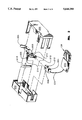
- FIG. 2 is an isometric exploded view of the misfold detector of FIG. 1.
- FIG. 3 shows a partial section of the misfold detector and the paper directing means of the printer of FIG. 1 with the paper normally moving longitudinally through the paper directing means without misfolding.
- FIG. 4 shows a partial section of the misfold detector and the paper directing means of the printer of FIG. 1 with misfolding paper above the stack activating the misfold detector.
- FIG. 5 shows a partial section of the misfold detector and the paper directing means of the printer of FIG. 1 with misfolding paper between the tractor drives and the paper directing means activating the misfold detector.
- FIG. 6 is an isometric view showing the misfold detector positioned on the paper directing means of the invention and the plug for connection to the printer.
- FIG. 7 is an enlargement of the portion of FIG. 6 showing the misfold detector mounted on paper deflecting means.
- FIG. 8 is a view of the circuit board of the printer into which a cable delivers signals from the misfold detector switch.
- FIG. 9 shows the routing of a cable from the printer output area to the circuit board of FIG. 8 for delivery of misfold detector signals.
- FIG. 1 shows printer 100 of the invention.
- Pins 102 of tractor drives 104 engage into sprocket holes (not shown) along each longitudinal edge of a continuous-form length 106 of paper, to move the continuous paper longitudinally from a source 108 of fanfold paper, through printing mechanism 110, through paper directing means 112 and downward at 116 toward generally horizontal surface 118 onto which the paper refolds onto output stack 120 in the same fanfold pattern as in the source.
- a set of chains 130 on the front side of the length 106 of paper hang vertically down from printer frame member 132; and similarly a set of chains 134 on the back side of the paper hang from printer frame member 136.
- the chains usually comprise hollow metal beads on a string or wire, or small interlocking links or any similar elongated member which does not catch the paper.
- the sets of chains interact with the folding length of paper.
- Source 108 of paper may be, for example, a cardboard box containing a paper stack folded at perforations.
- the pattern of the folds is similar to the pattern used in hand held oriental fans in which each fold 160 is bent, as shown, in the opposite direction in relation to previous fold 162 and subsequent fold 164.
- Misfold detector 180 is positioned at the paper directing means 112 to detect the jumble of paper accumulating either above or below the paper directing means as a result of misfolding.
- the printer of the invention may be provided using an optional kit to convert an existing printer to the printer of the invention.
- the kit includes the misfold detector of the invention and means for mounting the misfold detector switch in position to detect both misfolds between the tractor drive unit and the paper directing means and misfolds between the paper directing switch and the stack. Also the kit would contain means for signal communication between the misfold detector and the existing printer to operate tractor drives 104 depending on a signal from the paper misfold detector for stopping of printing when misfolds are detected.
- FIG. 2 shows misfold detector 180.
- Sensor 204 includes an emitter leg 208 and a detector leg 210.
- One end 212 of plate 206 is positioned between emitter leg 208 and detector leg 210.
- End 212 contains transparent window 214 through which a light beam (not shown) from the emitter leg 208 is directed to the detection leg 210 when the window is positioned between the legs.
- the plate 206 is attached to axle 216 which inserts through a hole in the base to allow plate 206 to rock about the axle.
- Bar spring 218 is inserted into split 222 in axle 216 to bias the plate in neutral position with the window between the two legs of the sensor.
- Lever 224 extends from plate 206 and any misfolding paper pushes on the lever to bend spring 218 and rock plate 206 so that the light beam is interrupted by the end 212 of plate 206 and the misfolding is detected.
- Base 202 limits the motion of plate 206 to protect spring 218 from excessive strain.
- Cover 226 snaps into position over base 202 in concert with base 202 protects the parts of the detector.
- Plug 128 is connected to the printer so that a signal indicating misfolding can be delivered through cable 230 to the printer to stop printing.
- Cable 230 is preferably a 4 conductor cable and plug 128 is preferably a 4 circuit in-line panel mount such as identified on page 8 of Catalog 87-803--Streamlined 8-88 for Soft-Shell Pin and Socket Connectors by AMP Incorporated of Harrisburg Pa., herein referred to as AMP Catalog 87-803.
- strain relief 232 is provided to prevent damage to the connection between the cable 230 and the plug 128 such as shown at page 10 in AMP Catalog 87-803.
- FIG. 3 shows the moving length of paper 106 traveling over paper directing means 112 and pulled downward by gravity toward the output paper stack 120 (see FIG. 1).
- the paper doesn't touch lever 224 and thus spring 218 biases window 214 in position for beam 250 directed from emitter leg 208 to travel through plate 206.
- FIG. 4 is similar to FIG. 3 except that misfold 252 of length 106 of moving paper between tractor drives 104 (see FIG. 1) and paper directing means 112, pushes down on lever 224 bending spring 218 and rocking plate 206 so beam 250, shown in phantom, is obstructed.
- the detector will generate a signal in cable 230 indicating misfolding and printing will be stopped.
- FIG. 5 is similar to FIG. 3 except the misfold 254 is between paper directing means 112 and printed output paper stack 120 (see FIG. 1). Paper misfold 254 pushes upward on detector lever 224, obstructing beam 250 and resulting in a signal output through cable 230 indicating misfolding.
- FIGS. 6 and 7 shows paper misfold detector 180 attached to paper deflecting means 112.
- Paper deflection means 112 includes a welded wire grid frame attachable to the printer.
- a bracket 302 is welded to wire 304, and base 202 is bolted (not shown) to bracket 302.
- Cable 224 is routed through spiral plastic wrapping 306 to the edge of the frame at 308. Wrapping 366 prevents interaction between the paper and the cable.
- Plug 128 is in position to connect into a receptacle (not shown) into the printer.
- the detector is positioned laterally in relation to length 106 of paper to be in communication with any misfolding paper for any common form width.
- FIG. 8 shows circuit board 309 with a connector 310 of 4 in-line protruding pins with which the misfold detector communicates to stop the printing if misfold is detected for preventing damage to the paper, jamming of paper movement, loss of data and complex procedures to restart printing.
- FIG. 9 shows the routing of connecting cable 312 between socket 314 into which plug 128 (see FIG. 2) is inserted and plug 316 which connects to the four in-line pins of circuit board 309 of FIG. 8.
- Socket or cap 314 is preferably a 4 circuit in-line cap such as shown at page 8 in AMP Catalog 87-803.
Landscapes
- Handling Of Sheets (AREA)
- Controlling Sheets Or Webs (AREA)
Abstract
A method for producing a printer wherein tractor drives move a length of fan-fold, continuous-form paper upwardly from a stacked source thereof, through a print mechanism, across a paper directing assembly and then downwardly to refold onto an output stack, the method including steps for detecting misfolds of the fan-fold paper in the printer.
Description
This is a division of application Ser. No. 08/165,230 filed Dec. 10, 1993, entitled "An Optical Sensor For A Jam-Free Continuous-Forms Printer", now U.S. Pat. No. 5,450,158 which is a division of application Ser. No. 07/938,182 filed Aug. 31, 1992 entitled "Jam-Free Continuous-Forms Printer", now U.S. Pat. No. 5,321,464 which are incorporated herein by reference.
Application Ser. No. 07/924,136 entitled "High Speed Continuous Forms Printer", now U.S. Pat. No. 5,300,008 incorporated herein by reference, discloses one or more upper chains and one or more lower chains to sweep against the refolding output stack at different times during different ranges of stack height.
Application Ser. No. 07/938,183 entitled Printer and Folder With Chains Having Light Weight Pendants Hanging Therefrom, now U.S. Pat. No. 5,350,246 incorporated herein by reference, discloses longate wire loops at the lower ends of chains to prevent entangling the chains with refolding paper.
This invention relates to high speed continuous-forms printing and, in particular, to misfold detection to prevent jamming during refold stacking of the continuous-forms subsequent to printing.
Information handling systems utilize high speed printers for rapidly generating printed information in a tangible form. High speed printers generally utilize xerographic or impact printing technologies. Impact printers are desirable for low cost and required where the option to print multipart forms is desired. The printing mechanism for impact printers generally transfer ink or other material from a print ribbon onto the paper to form images on one major surface of the paper.
Continuous-form paper is usually supplied from a box in which the paper is stacked in a fan-fold pattern. The paper may be single layer or may be multi-layer to provide multi-part forms. Continuous-form paper is perforated along lateral lines for dividing the continuous length into separable rectangular sheets or forms. Each of the separable sheets is rectangular and is typically 11.5 inches high by 14 and 7/8 inches wide. The paper is folded along the perforations in a zigzag manner reminiscent of oriental hand fans in which each lateral perforation is folded in the opposite direction from the preceding fold to form a stack.
Tractor drives engage a longitudinal row of holes along each edge of the paper for moving the paper longitudinally from the source box of paper, through the printing mechanism and downward toward a horizontal surface upon which it refolds into an output stack of printed, continuous forms. The tractor drives tend to distort the paper at the tractor holes in the edges of the paper so the refold stack is bowed upward at the edges. Typically, the paper length remains slightly folded along the lateral perforations after unstacking and printing and the descending paper length naturally tends to refold onto the stack at each lateral perforation in the same direction that it was originally folded.
Since the introduction of fanfold paper refolding, practitioners have faced the problem that occasionally the paper will fail to refold along the lateral perforations in the proper direction, eventually a jumble of output builds up resulting in tearing of the sprocket holes as the tractors drive the paper against the jumble resulting in jamming of paper movement through the tractor drives. It is known that the misfolding is related to the bowing of the stack due to the tractor damage and to the height of the paper discharge above the top of the stack and is also related to the intermittent characteristics of feeding of the paper through the printer.
The longitudinal movement of the paper through the printer is not continuous. Usually the movement is stopped as each line is printed on the sheets. Also, the paper tends to move quickly through blank lines and even more quickly through blank pages. For a very high speed paper tractor, the paper output is often accelerated so that descending paper bends as it falls into the stack and fails to properly refold onto the stack.
Also, the printer may not operate continuously. The output typically consists of separate reports which are transmitted to the printer as desired so that the printer is idle for minutes or even for hours between jobs. In addition, information handling systems tend to be idle for long periods due to schedules of working shifts, weekends and holidays. The paper in the printer may be idle with a lateral perforation in a straightened configuration so as to forget the original fold direction at the perforation; or the paper may be idle in a bent configuration and retain the bend so that it does not properly refold onto the output stack.
Once the stack is started in the proper location with the continuous length of paper refolding in the previous fan-fold directions, proper refolding tends to continue without any additional aid. However, occasionally the paper fails to refold in the desired direction which produces an unfolded jumble of printed output, and eventually applies forces to the paper moving through the tractor. The tractor tears out the sprocket holes in the paper causing the paper to stop moving through the printer.
In order to minimize data loss due to paper jamming practitioners have instituted jam detection schemes. For example, the rotation of a follower wheel in contact with the longitudinally moving length of paper can be compared with the movement of the tractor drives to detect jams.
U.S. Pat. No. 4,810,239 to Moss, incorporated herein by reference, discloses a misfolding paper detector. "When a jam causes a portion of the paper forms to be forced upwardly from the stack, that portion urges the interposing member upwardly also to block the projected beam and disable the printer." U.S. Pat. No. 4,030,720 discloses "a photoelectric switch . . . to detect the paper." U.S. Pat. Nos. 4,227,683 to Spangler et al. and 4,504,051 to Bittner et al. disclose optically sensing the height of a stack of fanfold paper to control an elevator which vertically positions the stack.
In unrelated arts optical means are used to sense jams. For example, U.S. Pat. No. 4,734,744 to Yamamoto which relates to copy machines, "the jam is detected if the [light] beam is not obstructed at regular intervals" and U.S. Pat. No. 4,716,286 to Taylor, which relates to money dispensing, discloses "sensors provided at spaced intervals along the common acceleration device determine if bills have reached the acceleration device . . . the adaptive technique compensates for changes in the sensor such as component aging and dust accumulation."
Accordingly, it is an object of this invention to provide a high speed continuous-forms printer which detects misfolding in the printed output refolding area prior to resulting jamming of paper movement through the printing mechanism.
It is another object to provide a process for reliably and economically operating a high speed continuous-forms printer without any loss of data resulting from occasional misfolding in the printed output refolding area leading to jamming of paper movement through the tractors.
It is another object of this invention to provide a high speed continuous forms printer adopted for using a misfold detector in the printed output refolding area to prevent jamming of paper movement through the printing mechanism and resulting loss of data.
It is finally an object of this invention to provide a detector adopted for converting an existing high speed continuous forms printer to the printer of this invention which detects misfolding prior to jamming of paper movement through the printing mechanism and resulting data loss.
In the applicant's invention the tractor drives of a high speed printer move a length of continuous-form paper longitudinally up from a box of fanfold stacked paper, through a print mechanism, through the tractor drives, across paper directing means, and downward for refolding onto a fanfold stack. Occasionally the refolding length of paper misfolds and the misfolding paper accumulates in a jumble between the tractor drives and paper directing means or between the paper directing means and the output paper stack. A paper misfold detector is provided at the paper directing means to detect any tangle of misfolding paper either above the stack or between the tractor drives and paper directing means.
Other features and advantages of this invention will become apparent from the following detailed description of the presently preferred embodiment and alternative embodiments of the invention, taken in conjunction with the accompanying drawings.
FIG. 1 schematically illustrates a side view of the printer of this invention with a misfold detector positioned at paper directing means to detect jumbling of paper either between the tractor and paper detecting means or between the detection means and the stack.
FIG. 2 is an isometric exploded view of the misfold detector of FIG. 1.
FIG. 3 shows a partial section of the misfold detector and the paper directing means of the printer of FIG. 1 with the paper normally moving longitudinally through the paper directing means without misfolding.
FIG. 4 shows a partial section of the misfold detector and the paper directing means of the printer of FIG. 1 with misfolding paper above the stack activating the misfold detector.
FIG. 5 shows a partial section of the misfold detector and the paper directing means of the printer of FIG. 1 with misfolding paper between the tractor drives and the paper directing means activating the misfold detector.
FIG. 6 is an isometric view showing the misfold detector positioned on the paper directing means of the invention and the plug for connection to the printer.
FIG. 7 is an enlargement of the portion of FIG. 6 showing the misfold detector mounted on paper deflecting means.
FIG. 8 is a view of the circuit board of the printer into which a cable delivers signals from the misfold detector switch.
FIG. 9 shows the routing of a cable from the printer output area to the circuit board of FIG. 8 for delivery of misfold detector signals.
FIG. 1 shows printer 100 of the invention. Pins 102 of tractor drives 104 engage into sprocket holes (not shown) along each longitudinal edge of a continuous-form length 106 of paper, to move the continuous paper longitudinally from a source 108 of fanfold paper, through printing mechanism 110, through paper directing means 112 and downward at 116 toward generally horizontal surface 118 onto which the paper refolds onto output stack 120 in the same fanfold pattern as in the source. A set of chains 130 on the front side of the length 106 of paper hang vertically down from printer frame member 132; and similarly a set of chains 134 on the back side of the paper hang from printer frame member 136. The chains usually comprise hollow metal beads on a string or wire, or small interlocking links or any similar elongated member which does not catch the paper. The sets of chains interact with the folding length of paper.
The printer of the invention may be provided using an optional kit to convert an existing printer to the printer of the invention. The kit includes the misfold detector of the invention and means for mounting the misfold detector switch in position to detect both misfolds between the tractor drive unit and the paper directing means and misfolds between the paper directing switch and the stack. Also the kit would contain means for signal communication between the misfold detector and the existing printer to operate tractor drives 104 depending on a signal from the paper misfold detector for stopping of printing when misfolds are detected.
FIG. 2 shows misfold detector 180. Within base 202 is positioned opaque sensor 204 and optic plate 206. Sensor 204 includes an emitter leg 208 and a detector leg 210. One end 212 of plate 206 is positioned between emitter leg 208 and detector leg 210. End 212 contains transparent window 214 through which a light beam (not shown) from the emitter leg 208 is directed to the detection leg 210 when the window is positioned between the legs. The plate 206 is attached to axle 216 which inserts through a hole in the base to allow plate 206 to rock about the axle. Bar spring 218 is inserted into split 222 in axle 216 to bias the plate in neutral position with the window between the two legs of the sensor. Lever 224 extends from plate 206 and any misfolding paper pushes on the lever to bend spring 218 and rock plate 206 so that the light beam is interrupted by the end 212 of plate 206 and the misfolding is detected. Base 202 limits the motion of plate 206 to protect spring 218 from excessive strain. Cover 226 snaps into position over base 202 in concert with base 202 protects the parts of the detector. Plug 128 is connected to the printer so that a signal indicating misfolding can be delivered through cable 230 to the printer to stop printing. Cable 230 is preferably a 4 conductor cable and plug 128 is preferably a 4 circuit in-line panel mount such as identified on page 8 of Catalog 87-803--Streamlined 8-88 for Soft-Shell Pin and Socket Connectors by AMP Incorporated of Harrisburg Pa., herein referred to as AMP Catalog 87-803. Preferably, strain relief 232 is provided to prevent damage to the connection between the cable 230 and the plug 128 such as shown at page 10 in AMP Catalog 87-803.
FIG. 3 shows the moving length of paper 106 traveling over paper directing means 112 and pulled downward by gravity toward the output paper stack 120 (see FIG. 1). The paper doesn't touch lever 224 and thus spring 218 biases window 214 in position for beam 250 directed from emitter leg 208 to travel through plate 206.
FIG. 4 is similar to FIG. 3 except that misfold 252 of length 106 of moving paper between tractor drives 104 (see FIG. 1) and paper directing means 112, pushes down on lever 224 bending spring 218 and rocking plate 206 so beam 250, shown in phantom, is obstructed. The detector will generate a signal in cable 230 indicating misfolding and printing will be stopped.
FIG. 5 is similar to FIG. 3 except the misfold 254 is between paper directing means 112 and printed output paper stack 120 (see FIG. 1). Paper misfold 254 pushes upward on detector lever 224, obstructing beam 250 and resulting in a signal output through cable 230 indicating misfolding.
FIGS. 6 and 7 shows paper misfold detector 180 attached to paper deflecting means 112. Paper deflection means 112 includes a welded wire grid frame attachable to the printer. A bracket 302 is welded to wire 304, and base 202 is bolted (not shown) to bracket 302. Cable 224 is routed through spiral plastic wrapping 306 to the edge of the frame at 308. Wrapping 366 prevents interaction between the paper and the cable. Plug 128 is in position to connect into a receptacle (not shown) into the printer. The detector is positioned laterally in relation to length 106 of paper to be in communication with any misfolding paper for any common form width.
FIG. 8 shows circuit board 309 with a connector 310 of 4 in-line protruding pins with which the misfold detector communicates to stop the printing if misfold is detected for preventing damage to the paper, jamming of paper movement, loss of data and complex procedures to restart printing.
FIG. 9 shows the routing of connecting cable 312 between socket 314 into which plug 128 (see FIG. 2) is inserted and plug 316 which connects to the four in-line pins of circuit board 309 of FIG. 8. Socket or cap 314 is preferably a 4 circuit in-line cap such as shown at page 8 in AMP Catalog 87-803.
While the currently preferred embodiment of this invention has been illustrated and described, various changes and modifications may be made therein within the scope of this invention which is defined by the following claims.
Claims (2)
1. A process for producing a printer, comprising the steps of:
providing printing means for producing images on the surface of a length of paper;
positioning tractor drive means in line with the printing means for moving the length of paper longitudinally through the printing means by engaging in holes along the longitudinal edges of the paper;
positioning surface means in line with and below the tractor drive means for stacking the continuous paper in a fanfold arrangement after printing;
positioning guide means in line between the tractor drive means and surface means for directing the paper from the tractor drive means downward toward the surface means for stacking in the fanfold arrangement;
positioning a misfold detector at the guide means for detecting misfolds either between the tractor drive means and guide means or between the guide means and the fanfold stack of paper by
positioning a lever so that misfolds between the tractor drive and guide means tend to move the lever in a first direction and misfolds between the guide means and the stack on the surface means tend to move the lever in an opposite direction; and
providing indicator means for generating a misfold signal if the lever is moved in either the first or the opposite the directions.
2. A process for producing a printer, comprising the steps of:
providing printing means for producing images on the surface of a length of paper;
positioning tractor drive means in line with the printing means for moving the length of paper longitudinally through the printing means by engaging in holes along the longitudinal edges of the paper;
positioning surface means in line with and below the tractor drive means for stacking the continuous paper in a fanfold arrangement after printing;
positioning guide means in line between the tractor drive means and surface means for directing the paper from the tractor drive means downward toward the surface means for stacking in the fanfold arrangement;
positioning a misfold detector at the guide means for detecting misfolds either between the tractor drive means and guide means or between the guide means and the fanfold stack of paper by
providing a lever positioned for interacting with misfolding paper;
providing a spring to bias the lever into a neutral position when paper is not misfolding;
providing a continuously active transmitter and a detector of the transmissions communicating with the lever so that when the lever is moved out of the neutral position by misfolding paper the transmissions received by the detector are changed and the change is detectable; and
providing means for transmitting a misfold detection signal depending on the detection of a change in the received transmissions.
Priority Applications (1)
| Application Number | Priority Date | Filing Date | Title |
|---|---|---|---|
| US08/433,628 US5644380A (en) | 1992-08-31 | 1995-05-03 | Producing a continuous-forms printer with a paper misfold detector |
Applications Claiming Priority (3)
| Application Number | Priority Date | Filing Date | Title |
|---|---|---|---|
| US07/938,182 US5321464A (en) | 1992-08-31 | 1992-08-31 | Jam-free continuous-forms printer |
| US08/165,230 US5450158A (en) | 1992-08-31 | 1993-12-10 | Optical sensor for a jam-free continuous-forms printer |
| US08/433,628 US5644380A (en) | 1992-08-31 | 1995-05-03 | Producing a continuous-forms printer with a paper misfold detector |
Related Parent Applications (1)
| Application Number | Title | Priority Date | Filing Date |
|---|---|---|---|
| US08/165,230 Division US5450158A (en) | 1992-08-31 | 1993-12-10 | Optical sensor for a jam-free continuous-forms printer |
Publications (1)
| Publication Number | Publication Date |
|---|---|
| US5644380A true US5644380A (en) | 1997-07-01 |
Family
ID=25471030
Family Applications (3)
| Application Number | Title | Priority Date | Filing Date |
|---|---|---|---|
| US07/938,182 Expired - Fee Related US5321464A (en) | 1992-08-31 | 1992-08-31 | Jam-free continuous-forms printer |
| US08/165,230 Expired - Lifetime US5450158A (en) | 1992-08-31 | 1993-12-10 | Optical sensor for a jam-free continuous-forms printer |
| US08/433,628 Expired - Fee Related US5644380A (en) | 1992-08-31 | 1995-05-03 | Producing a continuous-forms printer with a paper misfold detector |
Family Applications Before (2)
| Application Number | Title | Priority Date | Filing Date |
|---|---|---|---|
| US07/938,182 Expired - Fee Related US5321464A (en) | 1992-08-31 | 1992-08-31 | Jam-free continuous-forms printer |
| US08/165,230 Expired - Lifetime US5450158A (en) | 1992-08-31 | 1993-12-10 | Optical sensor for a jam-free continuous-forms printer |
Country Status (1)
| Country | Link |
|---|---|
| US (3) | US5321464A (en) |
Cited By (3)
| Publication number | Priority date | Publication date | Assignee | Title |
|---|---|---|---|---|
| US6111995A (en) * | 1998-05-07 | 2000-08-29 | Keyence Corporation | Multi-optical-path photoelectric switch |
| US6253996B1 (en) * | 1997-06-20 | 2001-07-03 | Oki Electric Industry Co., Ltd. | Medium handling apparatus |
| US7461484B2 (en) | 2002-02-15 | 2008-12-09 | Steelcase Inc. | Customizable partition system |
Families Citing this family (22)
| Publication number | Priority date | Publication date | Assignee | Title |
|---|---|---|---|---|
| US5321464A (en) * | 1992-08-31 | 1994-06-14 | International Business Machines Corporation | Jam-free continuous-forms printer |
| DE19633384B4 (en) * | 1995-10-30 | 2007-11-22 | Pentax Technologies Corp., Broomfield | Stacking system for continuous paper |
| KR0185047B1 (en) * | 1996-09-17 | 1999-05-15 | 김광호 | Printer feeder and method for preventing paper jams and creases |
| DE29716523U1 (en) * | 1997-09-05 | 1997-11-20 | Francotyp-Postalia AG & Co., 16547 Birkenwerder | Franking machine |
| US6750589B2 (en) * | 2002-01-24 | 2004-06-15 | Honeywell International Inc. | Method and circuit for the control of large arrays of electrostatic actuators |
| US7188837B2 (en) * | 2004-02-27 | 2007-03-13 | Hewlett-Packard Development Company, L.P. | Media detection |
| JP6077556B2 (en) | 2011-11-10 | 2017-02-08 | パックサイズ,エルエルシー | Conversion machine |
| WO2013106180A1 (en) * | 2012-01-09 | 2013-07-18 | Packsize Llc | Converting machine with an upward outfeed guide |
| US10093438B2 (en) | 2014-12-29 | 2018-10-09 | Packsize Llc | Converting machine |
| US10850469B2 (en) | 2016-06-16 | 2020-12-01 | Packsize Llc | Box forming machine |
| RU2737267C2 (en) | 2016-06-16 | 2020-11-26 | Пэксайз Ллс | System for production of workpieces for boxes and corresponding method |
| US11242214B2 (en) | 2017-01-18 | 2022-02-08 | Packsize Llc | Converting machine with fold sensing mechanism |
| SE541921C2 (en) | 2017-03-06 | 2020-01-07 | Packsize Llc | A box erecting method and system |
| SE540672C2 (en) | 2017-06-08 | 2018-10-09 | Packsize Llc | Tool head positioning mechanism for a converting machine, and method for positioning a plurality of tool heads in a converting machine |
| US11173685B2 (en) | 2017-12-18 | 2021-11-16 | Packsize Llc | Method for erecting boxes |
| US11247427B2 (en) | 2018-04-05 | 2022-02-15 | Avercon BVBA | Packaging machine infeed, separation, and creasing mechanisms |
| US11305903B2 (en) | 2018-04-05 | 2022-04-19 | Avercon BVBA | Box template folding process and mechanisms |
| DE112019003075T5 (en) | 2018-06-21 | 2021-03-25 | Packsize Llc | PACKAGING DEVICE AND SYSTEMS |
| SE543046C2 (en) | 2018-09-05 | 2020-09-29 | Packsize Llc | A box erecting method and system |
| US11524474B2 (en) | 2018-11-30 | 2022-12-13 | Packsize Llc | Adjustable cutting and creasing heads for creating angled cuts and creases |
| WO2020146334A1 (en) | 2019-01-07 | 2020-07-16 | Packsize Llc | Box erecting machine |
| US11701854B2 (en) | 2019-03-14 | 2023-07-18 | Packsize Llc | Packaging machine and systems |
Citations (5)
| Publication number | Priority date | Publication date | Assignee | Title |
|---|---|---|---|---|
| US3735975A (en) * | 1971-04-02 | 1973-05-29 | Eastman Kodak Co | Apparatus for fan fold stacking continuous strips of material |
| US4504051A (en) * | 1979-04-12 | 1985-03-12 | Genicom Corporation | Continuous forms refolder for high speed printers |
| US4566054A (en) * | 1983-07-20 | 1986-01-21 | Asahi Kogaku Kogyo Kabushiki Kaisha | Rack for mounting two electronic devices connectable to and disconnectable from each other |
| US4810239A (en) * | 1987-11-05 | 1989-03-07 | Storage Technology Corporation | Forms stacker jam detector |
| US5350246A (en) * | 1992-08-03 | 1994-09-27 | International Business Machines Corporation | High speed continuous-forms printer |
Family Cites Families (21)
| Publication number | Priority date | Publication date | Assignee | Title |
|---|---|---|---|---|
| GB1054192A (en) * | 1964-03-05 | 1967-01-04 | ||
| US4025187A (en) * | 1974-09-05 | 1977-05-24 | Xerox Corporation | Buckle control system |
| GB1501439A (en) * | 1975-05-06 | 1978-02-15 | Rank Xerox Ltd | Document handling apparatus |
| US4030720A (en) * | 1976-02-17 | 1977-06-21 | Jones Gary E | Paper stacker |
| US4213601A (en) * | 1978-11-06 | 1980-07-22 | Documation Incorporated | Printer elevator control mechanism |
| US4227683A (en) * | 1979-04-12 | 1980-10-14 | General Electric Company | Stack height sensor and elevator control for a continuous forms refolder |
| GB2051011B (en) * | 1979-05-08 | 1984-01-18 | Wofenet Ltd | Detachable continuous stationery feeding apparatus for photocopier |
| US4264200A (en) * | 1979-09-17 | 1981-04-28 | Xerox Corporation | Platen module for computer fanfold reproduction |
| US4313672A (en) * | 1979-09-17 | 1982-02-02 | Xerox Corporation | Stepper motor drive system in computer fanfold reproduction |
| US4300710A (en) * | 1979-11-29 | 1981-11-17 | Gradco-Dendoki, Inc. | Continuous form feeder |
| US4469320A (en) * | 1982-05-03 | 1984-09-04 | Xerox Corporation | Dual mode stack sensor |
| US4494948A (en) * | 1982-07-06 | 1985-01-22 | Sperry Corporation | Air controlled paper stacker |
| US4486093A (en) * | 1983-05-04 | 1984-12-04 | Mcnew Thomas A | System for passing elongated paper through a reproducing apparatus |
| US4597748A (en) * | 1984-10-04 | 1986-07-01 | Wolf Robert A | Method and apparatus for forming gauze pads |
| US4716286A (en) * | 1985-02-07 | 1987-12-29 | Brandt, Inc. | Electro-optical paper dispenser controller having a variable gain amplifier with digital input control means |
| US4714946A (en) * | 1985-11-27 | 1987-12-22 | International Business Machines Corporation | Continuous form feeder for a reproducing machine and process |
| JPS62194264A (en) * | 1986-02-20 | 1987-08-26 | Sharp Corp | Jam detecting device for intermediate tray part |
| US4878085A (en) * | 1987-04-28 | 1989-10-31 | Storage Technology Corporation | Cylinder and hub locking method and apparatus |
| US5081487A (en) * | 1991-01-25 | 1992-01-14 | Xerox Corporation | Cut sheet and computer form document output tray unit |
| US5321464A (en) * | 1992-08-31 | 1994-06-14 | International Business Machines Corporation | Jam-free continuous-forms printer |
| US5300008A (en) * | 1992-08-31 | 1994-04-05 | International Business Machines Corporation | Printer and folder with chains having light weight pendants hanging therefrom |
-
1992
- 1992-08-31 US US07/938,182 patent/US5321464A/en not_active Expired - Fee Related
-
1993
- 1993-12-10 US US08/165,230 patent/US5450158A/en not_active Expired - Lifetime
-
1995
- 1995-05-03 US US08/433,628 patent/US5644380A/en not_active Expired - Fee Related
Patent Citations (5)
| Publication number | Priority date | Publication date | Assignee | Title |
|---|---|---|---|---|
| US3735975A (en) * | 1971-04-02 | 1973-05-29 | Eastman Kodak Co | Apparatus for fan fold stacking continuous strips of material |
| US4504051A (en) * | 1979-04-12 | 1985-03-12 | Genicom Corporation | Continuous forms refolder for high speed printers |
| US4566054A (en) * | 1983-07-20 | 1986-01-21 | Asahi Kogaku Kogyo Kabushiki Kaisha | Rack for mounting two electronic devices connectable to and disconnectable from each other |
| US4810239A (en) * | 1987-11-05 | 1989-03-07 | Storage Technology Corporation | Forms stacker jam detector |
| US5350246A (en) * | 1992-08-03 | 1994-09-27 | International Business Machines Corporation | High speed continuous-forms printer |
Cited By (3)
| Publication number | Priority date | Publication date | Assignee | Title |
|---|---|---|---|---|
| US6253996B1 (en) * | 1997-06-20 | 2001-07-03 | Oki Electric Industry Co., Ltd. | Medium handling apparatus |
| US6111995A (en) * | 1998-05-07 | 2000-08-29 | Keyence Corporation | Multi-optical-path photoelectric switch |
| US7461484B2 (en) | 2002-02-15 | 2008-12-09 | Steelcase Inc. | Customizable partition system |
Also Published As
| Publication number | Publication date |
|---|---|
| US5450158A (en) | 1995-09-12 |
| US5321464A (en) | 1994-06-14 |
Similar Documents
| Publication | Publication Date | Title |
|---|---|---|
| US5644380A (en) | Producing a continuous-forms printer with a paper misfold detector | |
| US6581922B2 (en) | Sheet processing apparatus above image forming means and image forming apparatus | |
| DE69802128T2 (en) | Label printer with label edge sensor | |
| US4504162A (en) | Serial printer provided with cutter | |
| JP2003063072A (en) | Double side printing apparatus, double side printing system, and method for controlling sheet feed | |
| EP0386937A1 (en) | Color discrimination apparatus for color ink ribbon | |
| US5874901A (en) | Electronic equipment | |
| US5300008A (en) | Printer and folder with chains having light weight pendants hanging therefrom | |
| JP5507559B2 (en) | Member that detects the amount of media across multiple trays | |
| US7188837B2 (en) | Media detection | |
| US5150977A (en) | Recording apparatus with detector for paper edge and end of ribbon sensing | |
| US5350246A (en) | High speed continuous-forms printer | |
| JP3337277B2 (en) | Paper size detection device | |
| US6257781B1 (en) | Apparatus for tensioning a drive belt and for absorbing end-of-travel shock | |
| JP3432371B2 (en) | Printer | |
| US5961233A (en) | Continuous paper cutting device for a thermal printer | |
| US5478163A (en) | Method for guiding a document in a document-processing unit | |
| US20090122128A1 (en) | Tachograph for a motor vehicle, paper strip for a tachograph and method for aligning a longitudinally displaceable paper strip with respect to a printing device in a tachograph | |
| JP3808988B2 (en) | Continuous paper transport control system | |
| WO2001000517A1 (en) | Bail assembly | |
| US5180238A (en) | Dot impact printer | |
| KR100400635B1 (en) | Paper folding cassette for automatic post sealing apparatus | |
| JP2922585B2 (en) | Sheet size detection device | |
| JP2557851B2 (en) | Printer device | |
| JPS631196B2 (en) |
Legal Events
| Date | Code | Title | Description |
|---|---|---|---|
| FEPP | Fee payment procedure |
Free format text: PAYOR NUMBER ASSIGNED (ORIGINAL EVENT CODE: ASPN); ENTITY STATUS OF PATENT OWNER: LARGE ENTITY |
|
| FPAY | Fee payment |
Year of fee payment: 4 |
|
| REMI | Maintenance fee reminder mailed | ||
| REMI | Maintenance fee reminder mailed | ||
| LAPS | Lapse for failure to pay maintenance fees | ||
| LAPS | Lapse for failure to pay maintenance fees |
Free format text: PATENT EXPIRED FOR FAILURE TO PAY MAINTENANCE FEES (ORIGINAL EVENT CODE: EXP.); ENTITY STATUS OF PATENT OWNER: LARGE ENTITY |
|
| STCH | Information on status: patent discontinuation |
Free format text: PATENT EXPIRED DUE TO NONPAYMENT OF MAINTENANCE FEES UNDER 37 CFR 1.362 |
|
| FP | Lapsed due to failure to pay maintenance fee |
Effective date: 20050701 |