US5642964A - In-ground conduit system for geothermal applications - Google Patents
In-ground conduit system for geothermal applications Download PDFInfo
- Publication number
- US5642964A US5642964A US08/611,297 US61129796A US5642964A US 5642964 A US5642964 A US 5642964A US 61129796 A US61129796 A US 61129796A US 5642964 A US5642964 A US 5642964A
- Authority
- US
- United States
- Prior art keywords
- ground
- pipe
- conduit system
- heat
- hole
- Prior art date
- Legal status (The legal status is an assumption and is not a legal conclusion. Google has not performed a legal analysis and makes no representation as to the accuracy of the status listed.)
- Expired - Lifetime
Links
Images


Classifications
-
- E—FIXED CONSTRUCTIONS
- E21—EARTH DRILLING; MINING
- E21B—EARTH DRILLING, e.g. DEEP DRILLING; OBTAINING OIL, GAS, WATER, SOLUBLE OR MELTABLE MATERIALS OR A SLURRY OF MINERALS FROM WELLS
- E21B23/00—Apparatus for displacing, setting, locking, releasing, or removing tools, packers or the like in the boreholes or wells
- E21B23/01—Apparatus for displacing, setting, locking, releasing, or removing tools, packers or the like in the boreholes or wells for anchoring the tools or the like
-
- F—MECHANICAL ENGINEERING; LIGHTING; HEATING; WEAPONS; BLASTING
- F24—HEATING; RANGES; VENTILATING
- F24T—GEOTHERMAL COLLECTORS; GEOTHERMAL SYSTEMS
- F24T10/00—Geothermal collectors
- F24T10/10—Geothermal collectors with circulation of working fluids through underground channels, the working fluids not coming into direct contact with the ground
-
- Y—GENERAL TAGGING OF NEW TECHNOLOGICAL DEVELOPMENTS; GENERAL TAGGING OF CROSS-SECTIONAL TECHNOLOGIES SPANNING OVER SEVERAL SECTIONS OF THE IPC; TECHNICAL SUBJECTS COVERED BY FORMER USPC CROSS-REFERENCE ART COLLECTIONS [XRACs] AND DIGESTS
- Y02—TECHNOLOGIES OR APPLICATIONS FOR MITIGATION OR ADAPTATION AGAINST CLIMATE CHANGE
- Y02E—REDUCTION OF GREENHOUSE GAS [GHG] EMISSIONS, RELATED TO ENERGY GENERATION, TRANSMISSION OR DISTRIBUTION
- Y02E10/00—Energy generation through renewable energy sources
- Y02E10/10—Geothermal energy
Definitions
- the invention relates generally to the field of geothermal heating and air conditioning systems and in particularly to pipe systems used for in-ground heat exchange.
- the invention provides a system having in-ground conduit system which is simpler to install than previous conduit systems.
- Heat pump systems are increasingly popular for efficient heating and cooling of loads, for example as part of a heating-ventilation-air conditioning (HVAC) system for buildings.
- Heat pump systems generally include heat exchangers thermally coupled to the load and to a heat source or heat sink, the heat exchangers being connected in a refrigerant or coolant loop which includes a compressor and an expander. The compressor raises the pressure (and therefore the temperature) of the refrigerant and the expander lowers the pressure, producing a lower temperature in the refrigerant.
- a "ground source” heat pump which has the source/sink heat exchanger thermally conductively coupled to the ground, can extract a virtually limitless supply of thermal energy from the earth and transfer the energy to the load.
- a heat pump cools a load by extracting thermal energy from the load and transferring it to the earth for dissipation therein. In this manner the ground functions as either a heat sink or heat source.
- Modern day heat pumps for HVAC systems are equipped with reversing features such as valves to arrange the flow of refrigerant so that they may both heat and cool the load, as needed.
- a ground source heat pump requires a subterranean heat exchanger. While it is possible to use intermediate heat exchangers for transferring heat through thermally coupled fluid flow paths or the like, preferably the refrigerant or coolant is pumped through the pipes by the compressor and serves directly as the carrier for conveying the thermal energy to or from the ground. Thus, extra heat transfer losses, such as those inherent in ground water source systems, are avoided.
- the coolant is relatively heated by compression and cooled by expansion, leading to the respective heat exchangers, thereby raising the temperature of the hot side heat exchanger above the temperature of the load and lowering the temperature of the cool side heat exchanger below the temperature of the source, whereupon heat transfer occurs. Compression and expansion normally include a change of state of the coolant between liquid and gaseous states.
- the load heat exchanger is typically above ground and the ground heat exchanger is preferably well below the surface of the ground.
- Connecting pipes for the ground heat exchanger, and the pipes defined by the heat exchanger itself, can be horizontal, vertical or slanted.
- a typical installation may include combinations of these orientations, depending upon particular design criteria.
- the problem encountered in the installation of the pipes, particularly in a vertical or slanted orientation, is the tendency of the pipe to rise upward in the vertical or slanted hole after installation.
- a bore-hole is drilled and a double run of pipe connected by a U-bend fitting is inserted into the bore-hole.
- the pipe is usually inserted into the bore-hole by utilizing weights attached ot the U-bend fitting to force the pipe into the hole.
- the weights are usually retrieved using a line attached to the weights.
- the steel bars used for weights to force the piping into the well are retrieved, the piping has a tendency to come out of the well with the weights.
- an in-ground conduit system for a ground source heat pump comprising at least one conduit loop having two substantially parallel members connected by a U-shaped pipe member having a vertex and further comprising at least one wing member mounted on the conduit loop at or near the vertex such that the wing member contacts the ground in such a way as to resist upward movement of the conduit loop.
- a method of preventing a pipe conduit loop from moving upward in a bore-hole is achieved by attaching at least one wing member to the pipe such that the wing member extends out from the pipe such that in lowering the pipe into the bore-hole the wing member points generally upward so that the wing member will allow the pipe to be lowered into the bore-hole but will contact the ground so as to resist upward movement of the pipe.
- FIG. 1 is a simplified illustration of a geothermal heat pump system utilizing a vertical in-ground conduit system.
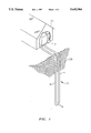
- FIG. 2 is an isometric illustration of a U-bend fitting for an in-ground conduit system having two wing members.
- FIG. 3 is an elevation view of the embodiment illustrated in FIG. 2.
- FIG. 4 is a section taken along line 4--4 of the embodiment of FIG. 3.
- FIG. 5 is an illustration of the use of the embodiment of FIGS. 2-4.
- FIG. 6 is an illustration of an alternate embodiment of the invention.
- FIG. 1 illustrates a geothermal heat pump system utilizing a vertical in-ground conduit system.
- Heat exchange fluid circulating through heat pump 2 moves through underground pipe 4, circulates through U-shaped pipe 6, moves up through underground pipe 8 and returns to heat pump 2.
- Underground pipes 4 and 8, along with U-shaped pipe 6, form in-ground conduit system 3.
- underground pipes 4 and 8 will be straight, substantially parallel to each other and have a vertical or slanted orientation, preferably a vertical orientation.
- the heat transfer fluid absorbs heat from the earth 28 during its circulation through the in-ground conduit system 3 and returns to the heat pump where the heat pump compresses the warm heat transfer fluid to a higher temperature, extracts the heat from it, and distributes the heat extracted through conventional duct systems in the building 10.
- FIG. 1 illustrates an example of a geothermal heat pump system using a single vertical ground loop for simplicity. However, most systems use more than one vertical loop, usually one loop for each ton of air conditioning capacity is used. The multiple loops are fused in parallel to a header pipe carrying the heat transfer fluid to and from the building. Alternately, systems can be arranged to use a slanted in-ground conduit system rather than a vertical in-ground conduit system.
- FIGS. 2-5 an embodiment of the present invention utilizing a pair wing members in accordance with the invention can be seen.
- U-bend fitting 12 can be seen.
- U-bend fitting 12 comprises U-shaped pipe 6, mounting bracket 14 and wing members 16 and 18.
- Mounting bracket 14 has a hole 20 (FIG. 4).
- the bracket 14 is positioned on U-shaped pipe 6 such that the hole is in the area of the vertex of the U-shaped pipe 6.
- Mounting bracket 14 can be attached to the U-shaped pipe 6 after it has been molded or, preferably, mounting bracket 14 is molded as an integral part of the U-shaped pipe 6.
- Wing members 16 and 18 are formed from a single length of material such as a suitable relatively small diameter plastic pipe. Although wing members 16 and 18 can be formed from any suitable material and can be separate pieces attached at hole 20, they are illustrated as being formed from a single length of material, shown as a tube. While the material forming wing members 16 and 18 can be any suitable material which is resilient enough to allow the in-ground conduit system to be lowered into a well hole and yet strong enough to prevent upward movement of the conduit system, as described below, it is presently preferred to use polyethylene as the material.
- the length of material is inserted into hole 20 provided in mounting bracket 14. After the length of the material is centered within the hole the length of material is bent until it crimps on both sides of the U-bend. This locks the material into mounting bracket 14.
- U-bend fitting 12 is attached to underground pipe 4 at end 22 of U-shaped pipe 6.
- end 24 of U-shaped pipe 6 is connected to underground pipe 8.
- the U-shaped pipe 6 is connected to underground pipes 4 and 8 so as to allow fluid flow communication such that the underground pipes along with the U-shaped pipe 6 accommodate a continuous loop for the fluid flow.
- Wing members 16 and 14 are positioned so that they point outward and upward from in-ground conduit system 3. Thus, when the pipe is being lowered into hole 26, the wing members will flex upwards to allow in-ground conduit system 3 to enter the hole and be lowered therein. However, when upward pressure is applied, wing members 14 and 16 will catch on the sides of the bore-hole coming into contact with the ground 28 and thus resisting the in-ground conduit system 3 from moving upward.
- FIG. 6 illustrates a second embodiment of an apparatus according to the invention.
- wing members 14 and 16 are mounted onto underground pipe 4.
- Wing members 14 and 16 can be mounted onto pipe 4 by any suitable method.
- Wing members 14 and 16 are positioned so that they flex toward the conduit loop when in-ground conduit system 3 is being lowered down into hole 26 and then contact the ground so as to resist upward movement of the pipe.
Abstract
An in-ground conduit system for a ground source heat pump is provided. The in-ground conduit system is a conduit-loop having at least one wing member mounted on the conduit loop such that the wing member contacts the ground in such a way so as to resist upward movement of the conduit loop.
Description
This application is a division of application Ser. No. 08/336,447, filed Nov. 9, 1994, now U.S. Pat. No. 5,533,356.
The invention relates generally to the field of geothermal heating and air conditioning systems and in particularly to pipe systems used for in-ground heat exchange. The invention provides a system having in-ground conduit system which is simpler to install than previous conduit systems.
Geothermal heating and air conditioning systems, i.e. heat pump systems, are increasingly popular for efficient heating and cooling of loads, for example as part of a heating-ventilation-air conditioning (HVAC) system for buildings. Heat pump systems generally include heat exchangers thermally coupled to the load and to a heat source or heat sink, the heat exchangers being connected in a refrigerant or coolant loop which includes a compressor and an expander. The compressor raises the pressure (and therefore the temperature) of the refrigerant and the expander lowers the pressure, producing a lower temperature in the refrigerant.
In heating a load, a "ground source" heat pump, which has the source/sink heat exchanger thermally conductively coupled to the ground, can extract a virtually limitless supply of thermal energy from the earth and transfer the energy to the load. A heat pump cools a load by extracting thermal energy from the load and transferring it to the earth for dissipation therein. In this manner the ground functions as either a heat sink or heat source. Modern day heat pumps for HVAC systems are equipped with reversing features such as valves to arrange the flow of refrigerant so that they may both heat and cool the load, as needed.
A ground source heat pump requires a subterranean heat exchanger. While it is possible to use intermediate heat exchangers for transferring heat through thermally coupled fluid flow paths or the like, preferably the refrigerant or coolant is pumped through the pipes by the compressor and serves directly as the carrier for conveying the thermal energy to or from the ground. Thus, extra heat transfer losses, such as those inherent in ground water source systems, are avoided. The coolant is relatively heated by compression and cooled by expansion, leading to the respective heat exchangers, thereby raising the temperature of the hot side heat exchanger above the temperature of the load and lowering the temperature of the cool side heat exchanger below the temperature of the source, whereupon heat transfer occurs. Compression and expansion normally include a change of state of the coolant between liquid and gaseous states.
The load heat exchanger is typically above ground and the ground heat exchanger is preferably well below the surface of the ground. Connecting pipes for the ground heat exchanger, and the pipes defined by the heat exchanger itself, can be horizontal, vertical or slanted. A typical installation may include combinations of these orientations, depending upon particular design criteria. The problem encountered in the installation of the pipes, particularly in a vertical or slanted orientation, is the tendency of the pipe to rise upward in the vertical or slanted hole after installation.
Generally, in installation of the slanted or vertical pipe, a bore-hole is drilled and a double run of pipe connected by a U-bend fitting is inserted into the bore-hole. The pipe is usually inserted into the bore-hole by utilizing weights attached ot the U-bend fitting to force the pipe into the hole. After the pipe is inserted, the weights are usually retrieved using a line attached to the weights. However, when the steel bars used for weights to force the piping into the well are retrieved, the piping has a tendency to come out of the well with the weights.
It would be advantageous to have a low cost method of resolving the foregoing problem.
It is an object of this invention to provide an in-ground conduit system which can have a vertical or slanted orientation and avoid the problem of the conduit system moving upward in the vertical or slanted hole.
In accordance with the present invention, there is provided an in-ground conduit system for a ground source heat pump comprising at least one conduit loop having two substantially parallel members connected by a U-shaped pipe member having a vertex and further comprising at least one wing member mounted on the conduit loop at or near the vertex such that the wing member contacts the ground in such a way as to resist upward movement of the conduit loop.
In accordance with another aspect of the present invention, there is provided a method of preventing a pipe conduit loop from moving upward in a bore-hole. This is achieved by attaching at least one wing member to the pipe such that the wing member extends out from the pipe such that in lowering the pipe into the bore-hole the wing member points generally upward so that the wing member will allow the pipe to be lowered into the bore-hole but will contact the ground so as to resist upward movement of the pipe.
FIG. 1 is a simplified illustration of a geothermal heat pump system utilizing a vertical in-ground conduit system.
FIG. 2 is an isometric illustration of a U-bend fitting for an in-ground conduit system having two wing members.
FIG. 3 is an elevation view of the embodiment illustrated in FIG. 2.
FIG. 4 is a section taken along line 4--4 of the embodiment of FIG. 3.
FIG. 5 is an illustration of the use of the embodiment of FIGS. 2-4.
FIG. 6 is an illustration of an alternate embodiment of the invention.
With continuing attention to the drawings wherein applied reference numerals indicate parts similarly hereinafter identified, FIG. 1 illustrates a geothermal heat pump system utilizing a vertical in-ground conduit system. Heat exchange fluid circulating through heat pump 2 moves through underground pipe 4, circulates through U-shaped pipe 6, moves up through underground pipe 8 and returns to heat pump 2. Underground pipes 4 and 8, along with U-shaped pipe 6, form in-ground conduit system 3. Typically underground pipes 4 and 8 will be straight, substantially parallel to each other and have a vertical or slanted orientation, preferably a vertical orientation. During the heating cycle, the heat transfer fluid absorbs heat from the earth 28 during its circulation through the in-ground conduit system 3 and returns to the heat pump where the heat pump compresses the warm heat transfer fluid to a higher temperature, extracts the heat from it, and distributes the heat extracted through conventional duct systems in the building 10.
During the cooling cycle, heat transfer fluid circulating through in-ground conduit system 3 ejects heat which is absorbed by the earth 28. The cooled heat transfer fluid then returns to the heat pump to pick up more heat removed from the building 10. FIG. 1 illustrates an example of a geothermal heat pump system using a single vertical ground loop for simplicity. However, most systems use more than one vertical loop, usually one loop for each ton of air conditioning capacity is used. The multiple loops are fused in parallel to a header pipe carrying the heat transfer fluid to and from the building. Alternately, systems can be arranged to use a slanted in-ground conduit system rather than a vertical in-ground conduit system.
With both the vertical and slanted in-ground conduit system difficulties arise installing the pipe because of the tendency of the pipe to move upward. Typically, this problem is encountered during installation when the weights, which were used to place the in-ground conduit system into the drilled hole, are taken out of the hole. At that time, the pipe has a tendency to move upward with the weights as they are being removed.
The present invention solves this problem by utilizing wing members attached to the in-ground conduit system of slanted or vertical pipes. Turning now to FIGS. 2-5, an embodiment of the present invention utilizing a pair wing members in accordance with the invention can be seen. In FIGS. 2-4, U-bend fitting 12 can be seen. U-bend fitting 12 comprises U-shaped pipe 6, mounting bracket 14 and wing members 16 and 18.
Referring now to FIG. 5, U-bend fitting 12 is attached to underground pipe 4 at end 22 of U-shaped pipe 6. Similarly, end 24 of U-shaped pipe 6 is connected to underground pipe 8. The U-shaped pipe 6 is connected to underground pipes 4 and 8 so as to allow fluid flow communication such that the underground pipes along with the U-shaped pipe 6 accommodate a continuous loop for the fluid flow.
FIG. 6 illustrates a second embodiment of an apparatus according to the invention. In FIG. 6, wing members 14 and 16 are mounted onto underground pipe 4. Wing members 14 and 16 can be mounted onto pipe 4 by any suitable method. Wing members 14 and 16 are positioned so that they flex toward the conduit loop when in-ground conduit system 3 is being lowered down into hole 26 and then contact the ground so as to resist upward movement of the pipe.
Changes may be made in the instruction, combination and arrangement of parts or elements as heretofore set forth in the specification and as shown in the drawings without departing from the spirit and scope of the invention, as defined in the following claims.
Claims (1)
1. U-bend fitting comprising:
U-shaped pipe having a vertex, a first member and a second member substantially parallel to said first; and
at least one wing member mounted onto said U-shaped pipe in the area of the vertex; and wherein said at least one wing member comprises a first wing member and a second wing member formed from a length of material having a first end portion and a second end portion wherein said length of material is crimped at a point between said first end portion and said second end portion and wherein the resulting crimped section is mounted in the area of the vertex of said U-shaped member such that said first end portion forms said first wing member and said second end portion forms said second wing member.
Priority Applications (1)
| Application Number | Priority Date | Filing Date | Title |
|---|---|---|---|
| US08/611,297 US5642964A (en) | 1994-11-09 | 1996-03-05 | In-ground conduit system for geothermal applications |
Applications Claiming Priority (2)
| Application Number | Priority Date | Filing Date | Title |
|---|---|---|---|
| US08/336,447 US5533356A (en) | 1994-11-09 | 1994-11-09 | In-ground conduit system for geothermal applications |
| US08/611,297 US5642964A (en) | 1994-11-09 | 1996-03-05 | In-ground conduit system for geothermal applications |
Related Parent Applications (1)
| Application Number | Title | Priority Date | Filing Date |
|---|---|---|---|
| US08/336,447 Division US5533356A (en) | 1994-11-09 | 1994-11-09 | In-ground conduit system for geothermal applications |
Publications (1)
| Publication Number | Publication Date |
|---|---|
| US5642964A true US5642964A (en) | 1997-07-01 |
Family
ID=23316134
Family Applications (3)
| Application Number | Title | Priority Date | Filing Date |
|---|---|---|---|
| US08/336,447 Expired - Fee Related US5533356A (en) | 1994-11-09 | 1994-11-09 | In-ground conduit system for geothermal applications |
| US08/611,296 Expired - Fee Related US5639184A (en) | 1994-11-09 | 1996-03-05 | In-ground conduit system for geothermal applications |
| US08/611,297 Expired - Lifetime US5642964A (en) | 1994-11-09 | 1996-03-05 | In-ground conduit system for geothermal applications |
Family Applications Before (2)
| Application Number | Title | Priority Date | Filing Date |
|---|---|---|---|
| US08/336,447 Expired - Fee Related US5533356A (en) | 1994-11-09 | 1994-11-09 | In-ground conduit system for geothermal applications |
| US08/611,296 Expired - Fee Related US5639184A (en) | 1994-11-09 | 1996-03-05 | In-ground conduit system for geothermal applications |
Country Status (1)
| Country | Link |
|---|---|
| US (3) | US5533356A (en) |
Cited By (15)
| Publication number | Priority date | Publication date | Assignee | Title |
|---|---|---|---|---|
| US6293120B1 (en) * | 1999-10-18 | 2001-09-25 | Kabushiki Kaisha Toko Kogyo | Building air conditioning system using geothermal energy |
| US6585047B2 (en) * | 2000-02-15 | 2003-07-01 | Mcclung, Iii Guy L. | System for heat exchange with earth loops |
| US6604577B2 (en) | 2000-12-05 | 2003-08-12 | Eric P. Mulder | Geothermal heat pump cleaning control system and method |
| US20040120773A1 (en) * | 2002-12-18 | 2004-06-24 | Alcatel | Protection element, method for laying cable in a groove system and cable layout |
| US20040238183A1 (en) * | 2003-05-29 | 2004-12-02 | Roesch Mark A. | Wellbore apparatus |
| US20050121169A1 (en) * | 2003-12-09 | 2005-06-09 | Mcnair Edward F. | Geothermal heating and/or cooling apparatus and method of using same |
| EP1853789A1 (en) * | 2005-02-28 | 2007-11-14 | Raymond Joseph Roussy | A method of geothermal loop installation |
| US20100040419A1 (en) * | 2005-02-28 | 2010-02-18 | Roussy Raymond | Method and system for installing micropiles with a sonic drill |
| US20100095617A1 (en) * | 2008-10-16 | 2010-04-22 | General Electric Wind Energy Gmbh | Wind turbine tower foundation containing power and control equipment |
| US20100124462A1 (en) * | 2005-02-28 | 2010-05-20 | Roussy Raymond J | Method and system for installing geothermal transfer apparatuses with a sonic drill |
| US20100155141A1 (en) * | 2005-02-28 | 2010-06-24 | Roussy Raymond | Method and system for installing geothermal transfer apparatuses with a sonic drill |
| WO2010122394A1 (en) * | 2009-04-20 | 2010-10-28 | Anzoic Energy Inc. | Subterranean continuous loop heat exchanger, method of manufacture and method to heat, cool or store energy with same |
| US20120282032A1 (en) * | 2009-02-04 | 2012-11-08 | Alain Desmeules | Geothermal flexible conduit loop single pass installation system for dense soils and rock |
| US9279228B1 (en) | 2013-03-14 | 2016-03-08 | Hercules Machinery Corporation | Pull-out resistant piles |
| CN111076452A (en) * | 2019-12-06 | 2020-04-28 | 东南大学 | Hollow row pile ground source heat exchange system based on underground prefabricated comprehensive pipe gallery |
Families Citing this family (26)
| Publication number | Priority date | Publication date | Assignee | Title |
|---|---|---|---|---|
| US6276438B1 (en) | 1995-09-12 | 2001-08-21 | Thomas R. Amerman | Energy systems |
| US6585036B2 (en) | 1995-09-12 | 2003-07-01 | Enlink Geoenergy Services, Inc. | Energy systems |
| US7017650B2 (en) * | 1995-09-12 | 2006-03-28 | Enlink Geoenergy Services, Inc. | Earth loop energy systems |
| US6250371B1 (en) | 1995-09-12 | 2001-06-26 | Enlink Geoenergy Services, Inc. | Energy transfer systems |
| US5590715A (en) * | 1995-09-12 | 1997-01-07 | Amerman; Thomas R. | Underground heat exchange system |
| US6041862A (en) * | 1995-09-12 | 2000-03-28 | Amerman; Thomas R. | Ground heat exchange system |
| US6672371B1 (en) | 1995-09-12 | 2004-01-06 | Enlink Geoenergy Services, Inc. | Earth heat exchange system |
| US6860320B2 (en) * | 1995-09-12 | 2005-03-01 | Enlink Geoenergy Services, Inc. | Bottom member and heat loops |
| US5833181A (en) * | 1997-03-18 | 1998-11-10 | Signlite Services, Inc. | Outdoor support post apparatus |
| US5992507A (en) * | 1998-03-20 | 1999-11-30 | Phillips Petroleum Company | Geothermal community loop field |
| DE10202261A1 (en) * | 2002-01-21 | 2003-08-07 | Waterkotte Waermepumpen Gmbh | Heat source or heat sink system with thermal earth coupling |
| US6955219B2 (en) | 2003-07-03 | 2005-10-18 | Enlink Geoenergy Services, Inc. | Earth loop installation with sonic drilling |
| US7418128B2 (en) * | 2003-07-31 | 2008-08-26 | Microsoft Corporation | Elastic distortions for automatic generation of labeled data |
| US7213649B2 (en) * | 2004-03-26 | 2007-05-08 | Mcnair Edward F | Geothermal pipe weight |
| US7438501B2 (en) | 2006-05-16 | 2008-10-21 | Layne Christensen Company | Ground freezing installation accommodating thermal contraction of metal feed pipes |
| JP4913497B2 (en) * | 2006-08-04 | 2012-04-11 | 株式会社リコー | Image forming apparatus and charging bias adjusting method |
| US7891440B2 (en) * | 2008-02-22 | 2011-02-22 | Roussy Raymond J | Method and system for installing geothermal transfer apparatuses with a sonic drill and a removable or retrievable drill bit |
| US8118115B2 (en) | 2008-02-22 | 2012-02-21 | Roussy Raymond J | Method and system for installing geothermal heat exchangers, micropiles, and anchors using a sonic drill and a removable or retrievable drill bit |
| US20090277602A1 (en) * | 2008-05-12 | 2009-11-12 | Tai-Her Yang | Temperature equalization air supply system of natural thermal energy with intermediate thermal storage |
| WO2010014910A1 (en) * | 2008-07-31 | 2010-02-04 | Walford Technologies, Inc | Geothermal heating, ventilating and cooling system |
| CA2704820A1 (en) | 2009-05-19 | 2010-11-19 | Thermapan Industries Inc. | Geothermal heat pump system |
| US9291286B2 (en) * | 2009-08-06 | 2016-03-22 | WCA Group LLC | Hollow drill rod for slurry application in a geothermal loop |
| US20110061832A1 (en) * | 2009-09-17 | 2011-03-17 | Albertson Luther D | Ground-to-air heat pump system |
| JP5974251B2 (en) * | 2012-08-21 | 2016-08-23 | ジャパンパイル株式会社 | Equipment for installing heat exchange tubes using underground heat in ready-made piles |
| US10094860B2 (en) * | 2015-03-30 | 2018-10-09 | Carrier Corporation | System and method for estimating energy consumption of an HVAC system |
| US10219415B2 (en) * | 2017-02-13 | 2019-02-26 | Facebook, Inc. | Server facility cooling system |
Citations (2)
| Publication number | Priority date | Publication date | Assignee | Title |
|---|---|---|---|---|
| US2554661A (en) * | 1947-06-20 | 1951-05-29 | Drayer Hanson Inc | Apparatus for exchanging heat with subterranean regions |
| US4538673A (en) * | 1984-05-02 | 1985-09-03 | Geo-Systems, Inc. | Drilled well series and paralleled heat exchange systems |
Family Cites Families (9)
| Publication number | Priority date | Publication date | Assignee | Title |
|---|---|---|---|---|
| CH579247A5 (en) * | 1973-07-04 | 1976-08-31 | Chapuis Henri | |
| SE426342B (en) * | 1982-04-23 | 1982-12-27 | Foerenade Fabriksverken | DEVICE FOR SEA LOCATED ROD HEAT EXCHANGERS FOR ANCHORING THE HEAT EXCHANGER AT THE SJONS BOTTEN |
| US4688717A (en) * | 1984-11-19 | 1987-08-25 | Curtis A. Jungwirth | Reverse cycle heating system for a building |
| US5108068A (en) * | 1989-08-30 | 1992-04-28 | Gingras Marc M | Support system for free standing poles or posts |
| US4993483A (en) * | 1990-01-22 | 1991-02-19 | Charles Harris | Geothermal heat transfer system |
| EP0578636B1 (en) * | 1990-10-22 | 1996-07-03 | BELLETTE, Rodney Walter | Anchorage device for use in sand or sandy soils |
| US5161561A (en) * | 1991-05-30 | 1992-11-10 | Jamieson Bruce W | Outdoor service system |
| US5224357A (en) * | 1991-07-05 | 1993-07-06 | United States Power Corporation | Modular tube bundle heat exchanger and geothermal heat pump system |
| US5305976A (en) * | 1992-11-09 | 1994-04-26 | Jack D. Blanchard | Stake supported post |
-
1994
- 1994-11-09 US US08/336,447 patent/US5533356A/en not_active Expired - Fee Related
-
1996
- 1996-03-05 US US08/611,296 patent/US5639184A/en not_active Expired - Fee Related
- 1996-03-05 US US08/611,297 patent/US5642964A/en not_active Expired - Lifetime
Patent Citations (2)
| Publication number | Priority date | Publication date | Assignee | Title |
|---|---|---|---|---|
| US2554661A (en) * | 1947-06-20 | 1951-05-29 | Drayer Hanson Inc | Apparatus for exchanging heat with subterranean regions |
| US4538673A (en) * | 1984-05-02 | 1985-09-03 | Geo-Systems, Inc. | Drilled well series and paralleled heat exchange systems |
Cited By (25)
| Publication number | Priority date | Publication date | Assignee | Title |
|---|---|---|---|---|
| US6293120B1 (en) * | 1999-10-18 | 2001-09-25 | Kabushiki Kaisha Toko Kogyo | Building air conditioning system using geothermal energy |
| US6585047B2 (en) * | 2000-02-15 | 2003-07-01 | Mcclung, Iii Guy L. | System for heat exchange with earth loops |
| US6604577B2 (en) | 2000-12-05 | 2003-08-12 | Eric P. Mulder | Geothermal heat pump cleaning control system and method |
| US20040120773A1 (en) * | 2002-12-18 | 2004-06-24 | Alcatel | Protection element, method for laying cable in a groove system and cable layout |
| US20040238183A1 (en) * | 2003-05-29 | 2004-12-02 | Roesch Mark A. | Wellbore apparatus |
| US6920924B2 (en) | 2003-05-29 | 2005-07-26 | The Lamson & Sessions Co. | Wellbore apparatus |
| US20050121169A1 (en) * | 2003-12-09 | 2005-06-09 | Mcnair Edward F. | Geothermal heating and/or cooling apparatus and method of using same |
| US7048037B2 (en) * | 2003-12-09 | 2006-05-23 | Mcnair Edward F | Geothermal heating and/or cooling apparatus and method of using same |
| US8136611B2 (en) | 2005-02-28 | 2012-03-20 | Roussy Raymond | Method and system for installing micropiles with a sonic drill |
| US8132631B2 (en) | 2005-02-28 | 2012-03-13 | Roussy Raymond J | Method of geothermal loop installation |
| US20100040419A1 (en) * | 2005-02-28 | 2010-02-18 | Roussy Raymond | Method and system for installing micropiles with a sonic drill |
| EP1853789A4 (en) * | 2005-02-28 | 2010-03-17 | Raymond Joseph Roussy | A method of geothermal loop installation |
| US8210281B2 (en) | 2005-02-28 | 2012-07-03 | Roussy Raymond | Method and system for installing geothermal transfer apparatuses with a sonic drill |
| US20100124462A1 (en) * | 2005-02-28 | 2010-05-20 | Roussy Raymond J | Method and system for installing geothermal transfer apparatuses with a sonic drill |
| US20100155141A1 (en) * | 2005-02-28 | 2010-06-24 | Roussy Raymond | Method and system for installing geothermal transfer apparatuses with a sonic drill |
| EP1853789A1 (en) * | 2005-02-28 | 2007-11-14 | Raymond Joseph Roussy | A method of geothermal loop installation |
| US8002502B2 (en) | 2005-02-28 | 2011-08-23 | Raymond J. Roussy | Method and system for installing cast-in-place concrete piles with a sonic drill |
| US20080083565A1 (en) * | 2005-02-28 | 2008-04-10 | Roussy Raymond J | Method of geothermal loop installation |
| US20100095617A1 (en) * | 2008-10-16 | 2010-04-22 | General Electric Wind Energy Gmbh | Wind turbine tower foundation containing power and control equipment |
| US20120282032A1 (en) * | 2009-02-04 | 2012-11-08 | Alain Desmeules | Geothermal flexible conduit loop single pass installation system for dense soils and rock |
| US9188368B2 (en) * | 2009-02-04 | 2015-11-17 | Brooke Erin Desantis | Geothermal flexible conduit loop single pass installation system for dense soils and rock |
| WO2010122394A1 (en) * | 2009-04-20 | 2010-10-28 | Anzoic Energy Inc. | Subterranean continuous loop heat exchanger, method of manufacture and method to heat, cool or store energy with same |
| CN102483271A (en) * | 2009-04-20 | 2012-05-30 | 安佐伊克能源公司 | Subterranean continuous loop heat exchanger, method of manufacture and method to heat, cool or store energy with same |
| US9279228B1 (en) | 2013-03-14 | 2016-03-08 | Hercules Machinery Corporation | Pull-out resistant piles |
| CN111076452A (en) * | 2019-12-06 | 2020-04-28 | 东南大学 | Hollow row pile ground source heat exchange system based on underground prefabricated comprehensive pipe gallery |
Also Published As
| Publication number | Publication date |
|---|---|
| US5533356A (en) | 1996-07-09 |
| US5639184A (en) | 1997-06-17 |
Similar Documents
| Publication | Publication Date | Title |
|---|---|---|
| US5642964A (en) | In-ground conduit system for geothermal applications | |
| US5025634A (en) | Heating and cooling apparatus | |
| US4257239A (en) | Earth coil heating and cooling system | |
| US4566532A (en) | Geothermal heat transfer | |
| US8833098B2 (en) | Direct exchange heating/cooling system | |
| US7451612B2 (en) | Geothermal exchange system incorporating a thermally superconducting medium | |
| US6450247B1 (en) | Air conditioning system utilizing earth cooling | |
| CN1330922C (en) | Heat pipe loop with pump assistance | |
| US6751974B1 (en) | Sub-surface and optionally accessible direct expansion refrigerant flow regulating device | |
| US20030221436A1 (en) | Recoverable ground source heat pump | |
| CN100491869C (en) | Geothermal heat exchanger and heat pump type air conditioner utilizing geothermal heat | |
| US7080524B2 (en) | Alternate sub-surface and optionally accessible direct expansion refrigerant flow regulating device | |
| US7146823B1 (en) | Horizontal and vertical direct exchange heating/cooling system sub-surface tubing installation means | |
| KR20090110904A (en) | Multi-faceted designs for a direct exchange geothermal heating/cooling system | |
| US10443909B2 (en) | Sub-surface insulation and well depth reduction for DX geothermal heat pump and refrigeration system | |
| US5509462A (en) | Ground source cooling system | |
| US4754614A (en) | Prime-motor-driven room warming/cooling and hot water supplying apparatus | |
| US4688717A (en) | Reverse cycle heating system for a building | |
| KR100812316B1 (en) | Heat pump system for using heat of rainwater heat source and geothermal | |
| CN101586855A (en) | Ground source cold accumulation device and ground source cold accumulation system | |
| US20040069013A1 (en) | Refrigerating or heat pump system with heat rejection at supercritical pressure | |
| CA1166242A (en) | Geothermal heat transfer | |
| KR100620907B1 (en) | Subterranean heat a house fever seive also heat pump type cooling and heating by subterranean heat a house fever seive | |
| US20190017733A1 (en) | Heat exchanger for use with earth-coupled air conditioning systems | |
| Kavanaugh | Ground-coupling with water source heat pumps |
Legal Events
| Date | Code | Title | Description |
|---|---|---|---|
| STCF | Information on status: patent grant |
Free format text: PATENTED CASE |
|
| FPAY | Fee payment |
Year of fee payment: 4 |
|
| FPAY | Fee payment |
Year of fee payment: 8 |
|
| FPAY | Fee payment |
Year of fee payment: 12 |
|
| REMI | Maintenance fee reminder mailed |