US564254A - Drying-closet - Google Patents
Drying-closet Download PDFInfo
- Publication number
- US564254A US564254A US564254DA US564254A US 564254 A US564254 A US 564254A US 564254D A US564254D A US 564254DA US 564254 A US564254 A US 564254A
- Authority
- US
- United States
- Prior art keywords
- chamber
- closet
- air
- bearing
- shaft
- Prior art date
- Legal status (The legal status is an assumption and is not a legal conclusion. Google has not performed a legal analysis and makes no representation as to the accuracy of the status listed.)
- Expired - Lifetime
Links
- 238000001035 drying Methods 0.000 description 7
- 238000010438 heat treatment Methods 0.000 description 5
- ZQTQPYJGMWHXMO-UHFFFAOYSA-N OOOOOOOOOOOOOOOOO Chemical compound OOOOOOOOOOOOOOOOO ZQTQPYJGMWHXMO-UHFFFAOYSA-N 0.000 description 4
- 241001168210 Mogulones Species 0.000 description 2
- 238000005266 casting Methods 0.000 description 2
- 238000005192 partition Methods 0.000 description 2
- 241001442654 Percnon planissimum Species 0.000 description 1
- 238000010521 absorption reaction Methods 0.000 description 1
- 238000010276 construction Methods 0.000 description 1
- 238000007599 discharging Methods 0.000 description 1
- 239000000463 material Substances 0.000 description 1
- 239000002184 metal Substances 0.000 description 1
- 238000000034 method Methods 0.000 description 1
- 238000003825 pressing Methods 0.000 description 1
- 208000022638 pyogenic arthritis-pyoderma gangrenosum-acne syndrome Diseases 0.000 description 1
- 239000007787 solid Substances 0.000 description 1
- 238000009423 ventilation Methods 0.000 description 1
- XLYOFNOQVPJJNP-UHFFFAOYSA-N water Substances O XLYOFNOQVPJJNP-UHFFFAOYSA-N 0.000 description 1
- 239000002023 wood Substances 0.000 description 1
Images

Classifications
-
- F—MECHANICAL ENGINEERING; LIGHTING; HEATING; WEAPONS; BLASTING
- F26—DRYING
- F26B—DRYING SOLID MATERIALS OR OBJECTS BY REMOVING LIQUID THEREFROM
- F26B15/00—Machines or apparatus for drying objects with progressive movement; Machines or apparatus with progressive movement for drying batches of material in compact form
Definitions
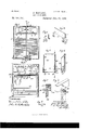
- My invention relates chiefly to improvements in closets for drying clothes, and the objects of my improvement are, first, to provide a hot closet in which avery strong blast may be used Without carrying dirt from the outside, or from the bearings or other parts of the closet, to the drying-chamber, in order to dry as quickly as possible without danger of soiling the clothes; second, to provide means for evenly distributing the blast in the drying-chamber without materially obstructing its passage; third, to provide means for concentrating the blast in a certain part of the drying-chamber when so desired; fourth, to provide a solid support for the fan, independent of the frame of the hot closet; fifth, to provide continuously-lubricated and adjustable bearings for the shaft which carries the fan; sixth, to provide means for ventilating the hot closet, which at the same time keep the inside bearings of the shaft carrying the fan cool; seventh, to provide movable draws or racks for the closet, which are noiseless in their operation, and so constructed that tie-rods, which are in the way, may be dispensed with
- Figure 1 is a central vertical longitudinal section of the closet along the line 1 1, Fig. 10.
- Fig. 2 is a vertical longitudinal section along the line 2 2, Fig. 10.
- Fig. 3 is a View of a detail.
- Fig. 4 is a View of another detail.
- Fig. 5 is an end elevation of a draw.
- Fig. 6 is a vertical section along the line 6 (i, Fig. 5.
- Fig. 7 is a vertical cross-section along the line 7 7, Fig. 8, of a clamp used to hold clothes while drying.
- Fig. 8 is an isometric View of the same part.
- Fig. 9 is a plan view of a detail.
- Fig. 10 is in part a vertical cross-section along the line 10 10, Fig. 1, and in part a vertical cross-section of parts located above the top of the hot closet.
- Fig. 11 is an end eleva- Serial No. 551,303, (No model.)
- Fig.' 12 is a vertical crosssection along the line 12 12, Fig. 11.
- Fig. 13 is an elevation of a detail.
- Fig. 14 is a plan View of a bearing, and Fig. 15 is a vertical cross-section of the same part along the line 15 15,- Fig. 14..
- the hot closet is preferably divided into four chambersviz., a central chamber A, a chamber B in the top of the closet, and chambers O O on each side of the chamber A.
- Partitions 4 4 divide the chamber A from the chambers O 0, except at the bottom, to which they do not extend.
- the chamber A is partially divided from the chamber B by the top 5, preferably beveled to prevent lint or dirt collecting on it, substantially as shown. Through the top 5 of the chamber A there is an air-passage 5.
- the chambers C O communicate with the chamber B at their upper ends, and with the chamber A at their lower ends.
- 1 1 are the end walls, 0 c the side walls, and 2 the top of the closet.
- the chamber A preferably contains two radiators 3 3, which may be of ordinary con-' struction.
- a centrifugal fan 6 is located above the opening 5 in the top 5 of the chamber A . It may be of ordinary construction, but its upper side is preferably closed by a top 10, which is preferably beveled to prevent dirt or lint from accumulating upon it, and also to make it easier to reach and clean.
- the fan 6 is attached to the vertical shaft 7, from which it receives its motion. This shaft extends up through an opening 2 in the top 2 of the closet. The opening is preferably just large enough to permit the shaft to pass through without touching.
- the shaft 7 turns in bearings, preferably constructed and arranged as follows: The upper bearing is preferably selfadjusting and self-oiling. An oil-cup 11 is preferably carried by the shaft, whose bottom 12 is bored to fit the shaft 7, to which it is attached.
- An oil-tight joint is made around the shaft, preferably by means of a ring 13, of lead or other suitable material.
- the cup preferably contains an annular enlargement just below its upper edge. The enlargement a point a little below the center of the bear ing.
- On the outside of each arm a groove 16, having beveled sides, is formed, and 111 this groove a small block E, having beveled.
- the slot 6 allows the plate E to be moved vertically in the groove 16, in which it is located.
- the plate E has a cavity 19 near its lower end, preferably, to receive the end of a set-screw 20, for holding the bearing in place.
- the bearing D is preferably suspended from the ceiling or other support above by means of a bracket F, having arms 9, to whose lower end a ring 21 is attached, and through which ring the set-screws pass.
- the casting D being pivoted on the set-screws 20 at points about on a level with the center of the bearing, allows the bearing to adjust itself to the shaft.
- the bearing may be raised or lowered by means of the slots 17 in the plate E.
- a pulley 8 is preferably attached to the shaft 7, whose hub and rim are preferably connected by means of a disk, which prevents any oil from dropping from the upper bearing of the shaft 7, either onto the top of the closet or through the openin g therein and into the chamber B beneath.
- the lower bearing G consists of the box 22, for holding a supply of oil, and having the flange 23, by which it is bolted to the fioor, and on the inside of which, a short distance from the bottom, preferably, a seat 24 for a ball 25 is formed.
- the ball 25 contains a bearing 9 for the lower end of the shaft.
- the bottom of this hearing is connected with the space belowthe ball by means of a hole 29. by a hole 28, with a chamber 27 below it, and said chamber 27 is connected with the space above the ball-seat by one or more holes 26.
- Preferably only enough oil is used in the box 22 to properly'lubricate the lower bearing.
- the lower bearing of the shaft 7 is preferably protected from heat from the radiators and the hot air surrounding it by a casing 30, which encirclesthe bearing and preferably extends up to a point higher than the bottom
- the seat 24E of the ball is connected of the partitions 4..
- the interior of this cas ing 30 is connected with the outer air by means of a cold-air inlet 31.
- the top of the casing 30 is open.
- I preferably use a pipe 32 for carrying off the hot air and vapor from the closet. That portion within the closet extends across the chamber A preferably close to the passage leading from one of the chambers 0 into chamber A, and air and vapor is preferably given access to the interior of the pipe through perforations which are preferably formed in the side of the pipe facing said air-passage.
- the portion of the pipe outside of said hot closetp' referably extends upward to about the top or above it, as represented in Fig. 2. The draft through this outside flue and the fact that the air is driven into the perforations in said pipe by the force with which it passes from the chamber C toward the chamber A cause a continuous escape of hot air and vapor during the operation of the apparatus.
- the fan 6 gives the air a rotary motion which tends to throw most of the air on each side to one end of the chamber C on that side instead of distributing it evenly.
- the plate at the other extreme end is preferably vertical, but not necessarily so.
- the lower edges of these plates are preferably each fastened to a rod 34,the ends of which preferably rest in notches 3i in the slats 35, which are preferably fastened to the sides of the drying-chamber, as shown.
- the rod 34: of the end plate, which is preferably vertical, is preferably longer than the others, and passes through the wall 0 of the hot closet to the outside, and has a lever 36 attached thereto, which maybe provided with a hook 37 to engage in a screweye 37 in the wall of the hot closet.
- the other plates are connected with the plates with which the lever 36 is connected by means, preferably, of the links 38, staples 39, and hooks 40.
- any number of the plates 38 may be disconnected from the vertical plate and allowed to assume a horizontal position, thus covering the whole or a part of the drying-chamber beneath, and cutting off the blast therefrom, thus concentrating the blast on the part of the drying-chamber which is not covered, or, where the whole top of one of the drying-chambers C is covered, concentrating the entire blast from the fan upon the other chamber.
- Movable draws or racks are used to hang the clothes on, preferably.
- These draws preferably each consists of two end boards 41 41, each preferably provided with a strengthening-piece 42 across one end. The. ends of the boards 41 are preferably connected by tie-rods 43, passing through the strengthening-piece 42.
- the piece 42 is preferably rectangular in cross-section, and has a flange 44 on one edge, which overlaps the end board to which it is connected, and is preferably bolted thereto.
- the lugs 45 each has cast on its outer end, or otherwise attached to it, a short arm 46, having the bearings 47, and in the bearings 47 in each pair of lugs a shaft 48, carrying rollers 49 49, is journaled.
- the rollers 49 are preferably keyed to the shaft 48, or attached thereto by other suitable means.
- the end of the boards 41 opposite that to which the rollers 49 are attached is braced by the rods 50, one end of each of which is attached to one of the rods 43, preferably by screwing it onto the end of said rod, and the other end of which is bolted or otherwise attached to the end board, substantially as shown in Figs. 5 and 6. Both ends of each draw are preferably alike.
- the draws one above the otherin pairs, as represented in Fig. 2. Their size or height may be adapted to the size of the articles to be dried therein.
- the lower one runs on a track 52, Fig. 10, and is preferably the smaller.
- the upper one in such cases runs on rails 52 52, whose ends, as do those of the rails in the lower track, extend out beyond the end of the chamber O, in which the draws are used.
- the lower draw is preferably provided with one or more bars 53, upon which collars and cuffs may be hung. These bars are preferably removably connected with the ends of the draw. If desired, the whole chamber may be occupied by a single draw, like 41 which preferably rests upon rails running on the floor.
- WVhere two draws are arranged as shown, one above the other, they may be used as one for drying large articles. WVhen so used, the bars 53 are preferably lifted out of the lower draw.
- the rollers on which the draws run preferably fit the rails on which they run.
- Their bearings 47 are preferably lined with antifrictionmetal to prevent them from squeaking, as it is undesirable to use oil in a hot closet for any purpose.
- One or more bars 58 are attached to the upper ends of the end boards 41, and to these bars 58 I attach clamps which each consist of a pair of pins 55, preferably made of wood, and rounded and pointed at one end and perforated at the opposite end.
- the pair of pins 55 constituting the clamp, are hung on a pin 5'7, projecting from the bar 58, and are held against the bar and against each other by a staple 59 and a spring 60, the staple being driven into the bar over the pins and the spring preferably slipped over the staple, with one end hooked therein and the other end pressing against the pins.
- the rounded ends of the pins extend below the edge of the bar 58. The goods are slipped up between the pins, and are held by the tension of the spring.
- the draws are preferably drawn out through one end of the chamber in which they are respectively located.
- the end of the chamber is left open to permit of this, and is prefer ably closed by the end board or end boards of the draw or draws used therein when such draw or draws are in place, as shown in Fig. 2.
- the operation of my improved closet is preferably as follows: Cold air enters the chamber A through the air-inlet 31 and casing 30, and tends to keep the bearing of the lower end of the shaft '7 cool.
- the air is heated in the chamber A by the radiators 3 or other suitable means. I prefer to always heat the air above 212 Fahrenheit, and the best results are obtained when it is heated to about 220.
- the fan 6 being set in motion by means of power transmitted through the pulley 8 to the shaft 7, upon which the fan is mounted, exhausts the air from the chamber A, draws it up into the chamber B, andforces it thence down into the chambers C O. From the chambers C C it in part passes back into the chamber A, and in part escapes from the hot closet through the outlet-pipe 32.
- I claim 1 The combination in a hot closet of a central air-chamber A, means for heating air lo cated therein; a drying-chamber O at the side of chamber A; a cold-air inlet opening into the bottom part of chamber A; the chamber 13 at the top of the closet; passages connecting chamber 13 with the tops of chambers A and C; a passage connectiu g the bottoms of chambers A and C an escape-flue leading upward from near the bottom of the chamber A, and means causing the air to circulate through said chambers substantially as described.
- a hot closet of a chamber containing means heating air admitted thereto; a cold-air inlet near the bottom of said chamber; a hot-air outlet near the bottom of the hot closet; one or more drying-chambeis whose tops are connected by hot-air passages, with the top of said heatingchamber, and whose bottoms are connected with the bottom of said heatin g-chamber; an d means for forcing the hot air to circulate from said hcatingchamber down through said drying chamber or chambers, and thence in whole orin part, back into said heating-chant ber; substantially as described.
Landscapes
- Engineering & Computer Science (AREA)
- Mechanical Engineering (AREA)
- General Engineering & Computer Science (AREA)
- Drying Of Solid Materials (AREA)
Description
v 11 1 2 Sheets-Sheet 1.
J. MGGLONE.
DRYING GLOSET.
Patnted July 21, 1896.
(No Model.)
2 Sheets-Sheet 2. J. MOG'LONE.
DRYING CLOSET.
No. 564,254. Patented July 21, 1896.
OOOOOOOOOOOOOOOOO OOOOOOOOOOOOOOOOO 00 000000000000000 2 5 0 ooooooooooooooooos MW OOOOOOOOOOOOOOOOO OOOOOOOOOOOOOOOOO Azies MQXM IKE "cams Papas cu. FNOTOUTHQ. WASHXNGTGN. n. c
UNITED STATES PATENT FFIoE.
JOHN MOGLONE, OF ST. LOUIS, MISSOURI.
DRYING-CLOSET.
SPECIFICATION forming part of Letters Patent No. 564,254, dated July 21, 1896.
Applicati n filed May 31, 1895.
T aZZ whom, it may concern: 1
Be it known that I, JOHN MOGLONE, a citizen of the United States, residing at St. Louis, in the State of Missouri, have invented a new and useful Improvement in Hot Closets, of which the following is a specification.
My invention relates chiefly to improvements in closets for drying clothes, and the objects of my improvement are, first, to provide a hot closet in which avery strong blast may be used Without carrying dirt from the outside, or from the bearings or other parts of the closet, to the drying-chamber, in order to dry as quickly as possible without danger of soiling the clothes; second, to provide means for evenly distributing the blast in the drying-chamber without materially obstructing its passage; third, to provide means for concentrating the blast in a certain part of the drying-chamber when so desired; fourth, to provide a solid support for the fan, independent of the frame of the hot closet; fifth, to provide continuously-lubricated and adjustable bearings for the shaft which carries the fan; sixth, to provide means for ventilating the hot closet, which at the same time keep the inside bearings of the shaft carrying the fan cool; seventh, to provide movable draws or racks for the closet, which are noiseless in their operation, and so constructed that tie-rods, which are in the way, may be dispensed with, and, eighth, to provide means for holding the clothes while drying. I attain these objects by the mechanism illustrated in the accompanying drawings, in which Figure 1 is a central vertical longitudinal section of the closet along the line 1 1, Fig. 10. Fig. 2 is a vertical longitudinal section along the line 2 2, Fig. 10. Fig. 3is a View of a detail. Fig. 4is a View of another detail. Fig. 5 is an end elevation of a draw. Fig. 6 is a vertical section along the line 6 (i, Fig. 5. Fig. 7 is a vertical cross-section along the line 7 7, Fig. 8, of a clamp used to hold clothes while drying. Fig. 8 is an isometric View of the same part. Fig. 9 is a plan view of a detail. Fig. 10 is in part a vertical cross-section along the line 10 10, Fig. 1, and in part a vertical cross-section of parts located above the top of the hot closet.
Fig. 11 is an end eleva- Serial No. 551,303, (No model.)
tion of a detail. Fig.' 12 is a vertical crosssection along the line 12 12, Fig. 11. Fig. 13 is an elevation of a detail. Fig. 14 is a plan View of a bearing, and Fig. 15 is a vertical cross-section of the same part along the line 15 15,- Fig. 14..
Similar letters and numerals refer to similar parts throughout the several views.
The hot closet is preferably divided into four chambersviz., a central chamber A, a chamber B in the top of the closet, and chambers O O on each side of the chamber A. Partitions 4 4 divide the chamber A from the chambers O 0, except at the bottom, to which they do not extend. The chamber A is partially divided from the chamber B by the top 5, preferably beveled to prevent lint or dirt collecting on it, substantially as shown. Through the top 5 of the chamber A there is an air-passage 5.
The chambers C O communicate with the chamber B at their upper ends, and with the chamber A at their lower ends. 1 1 are the end walls, 0 c the side walls, and 2 the top of the closet.
The chamber A preferably contains two radiators 3 3, which may be of ordinary con-' struction.
Above the opening 5 in the top 5 of the chamber A a centrifugal fan 6 is located. It may be of ordinary construction, but its upper side is preferably closed by a top 10, which is preferably beveled to prevent dirt or lint from accumulating upon it, and also to make it easier to reach and clean. The fan 6 is attached to the vertical shaft 7, from which it receives its motion. This shaft extends up through an opening 2 in the top 2 of the closet. The opening is preferably just large enough to permit the shaft to pass through without touching. The shaft 7turns in bearings, preferably constructed and arranged as follows: The upper bearing is preferably selfadjusting and self-oiling. An oil-cup 11 is preferably carried by the shaft, whose bottom 12 is bored to fit the shaft 7, to which it is attached. An oil-tight joint is made around the shaft, preferably by means of a ring 13, of lead or other suitable material. The cup preferably contains an annular enlargement just below its upper edge. The enlargement a point a little below the center of the bear ing. On the outside of each arm a groove 16, having beveled sides, is formed, and 111 this groove a small block E, having beveled.
edges, is fitted and held to the arm by a bolt 18, passing through a slot e in the upper end of the plate E. The slot 6 allows the plate E to be moved vertically in the groove 16, in which it is located. The plate E has a cavity 19 near its lower end, preferably, to receive the end of a set-screw 20, for holding the bearing in place. The bearing D is preferably suspended from the ceiling or other support above by means of a bracket F, having arms 9, to whose lower end a ring 21 is attached, and through which ring the set-screws pass. The casting D being pivoted on the set-screws 20 at points about on a level with the center of the bearing, allows the bearing to adjust itself to the shaft. The bearing may be raised or lowered by means of the slots 17 in the plate E.
Beneath the upper bearing and between it and the top of the hot closet a pulley 8 is preferably attached to the shaft 7, whose hub and rim are preferably connected by means of a disk, which prevents any oil from dropping from the upper bearing of the shaft 7, either onto the top of the closet or through the openin g therein and into the chamber B beneath.
The lower bearing G consists of the box 22, for holding a supply of oil, and having the flange 23, by which it is bolted to the fioor, and on the inside of which, a short distance from the bottom, preferably, a seat 24 for a ball 25 is formed. The ball 25 contains a bearing 9 for the lower end of the shaft. The bottom of this hearing is connected with the space belowthe ball by means of a hole 29. by a hole 28, with a chamber 27 below it, and said chamber 27 is connected with the space above the ball-seat by one or more holes 26. Preferably only enough oil is used in the box 22 to properly'lubricate the lower bearing. As the shaft rotates the oil is thrown outward and upward in the bearing, but is able to pass down again through the passage or passages 26 to the chamber 27. This keeps the bearing clean and perfectly lubricated. Any dirt which may come from the wear of thebearing or other source settles in the chamber 27 below the seat.
The lower bearing of the shaft 7 is preferably protected from heat from the radiators and the hot air surrounding it by a casing 30, which encirclesthe bearing and preferably extends up to a point higher than the bottom The seat 24E of the ball is connected of the partitions 4.. The interior of this cas ing 30 is connected with the outer air by means of a cold-air inlet 31. The top of the casing 30 is open.
I preferably use a pipe 32 for carrying off the hot air and vapor from the closet. That portion within the closet extends across the chamber A preferably close to the passage leading from one of the chambers 0 into chamber A, and air and vapor is preferably given access to the interior of the pipe through perforations which are preferably formed in the side of the pipe facing said air-passage. The portion of the pipe outside of said hot closetp'referably extends upward to about the top or above it, as represented in Fig. 2. The draft through this outside flue and the fact that the air is driven into the perforations in said pipe by the force with which it passes from the chamber C toward the chamber A cause a continuous escape of hot air and vapor during the operation of the apparatus.
The fan 6 gives the air a rotary motion which tends to throw most of the air on each side to one end of the chamber C on that side instead of distributing it evenly. To avoid that difficulty, I place a number of plates 33 33, &c., and which are preferably rectangular, crosswise in the chamber B above each of the chambers C. These plates may be vertical, or the plates at the end toward which the air is moving may be advantageously inclined, as shown, so as to slightly obstruct the air at that end. The plate at the other extreme end is preferably vertical, but not necessarily so. The lower edges of these plates are preferably each fastened to a rod 34,the ends of which preferably rest in notches 3i in the slats 35, which are preferably fastened to the sides of the drying-chamber, as shown. The rod 34: of the end plate, which is preferably vertical, is preferably longer than the others, and passes through the wall 0 of the hot closet to the outside, and has a lever 36 attached thereto, which maybe provided with a hook 37 to engage in a screweye 37 in the wall of the hot closet. The other plates are connected with the plates with which the lever 36 is connected by means, preferably, of the links 38, staples 39, and hooks 40. If desired, any number of the plates 38 may be disconnected from the vertical plate and allowed to assume a horizontal position, thus covering the whole or a part of the drying-chamber beneath, and cutting off the blast therefrom, thus concentrating the blast on the part of the drying-chamber which is not covered, or, where the whole top of one of the drying-chambers C is covered, concentrating the entire blast from the fan upon the other chamber. As will be obvious, it is necessary where the whole of the cham her 0 is to be closed to bring the plate 33 to which the lever is attached to a substantially horizontal position as well as the other 'plates,and where that is done it is unnecessary to disconnect the plates from each other. By simply unlinking the plates from each other they may be lifted out and removed for cleansing.
Movable draws or racks are used to hang the clothes on, preferably. These draws preferably each consists of two end boards 41 41, each preferably provided with a strengthening-piece 42 across one end. The. ends of the boards 41 are preferably connected by tie-rods 43, passing through the strengthening-piece 42. The piece 42 is preferably rectangular in cross-section, and has a flange 44 on one edge, which overlaps the end board to which it is connected, and is preferably bolted thereto. On each end of this part, which is preferably a casting, and at right angles thereto, there is a hollow lug 45, through which the tie-rods 43 43 pass. The object of these lugs is to give the rods a larger bearing than they otherwise would have. The lugs 45 each has cast on its outer end, or otherwise attached to it, a short arm 46, having the bearings 47, and in the bearings 47 in each pair of lugs a shaft 48, carrying rollers 49 49, is journaled. The rollers 49 are preferably keyed to the shaft 48, or attached thereto by other suitable means. The end of the boards 41 opposite that to which the rollers 49 are attached is braced by the rods 50, one end of each of which is attached to one of the rods 43, preferably by screwing it onto the end of said rod, and the other end of which is bolted or otherwise attached to the end board, substantially as shown in Figs. 5 and 6. Both ends of each draw are preferably alike.
I prefer to arrange the draws one above the otherin pairs, as represented in Fig. 2. Their size or height may be adapted to the size of the articles to be dried therein. 'The lower one runs on a track 52, Fig. 10, and is preferably the smaller. The upper one in such cases runs on rails 52 52, whose ends, as do those of the rails in the lower track, extend out beyond the end of the chamber O, in which the draws are used. The lower draw is preferably provided with one or more bars 53, upon which collars and cuffs may be hung. These bars are preferably removably connected with the ends of the draw. If desired, the whole chamber may be occupied by a single draw, like 41 which preferably rests upon rails running on the floor. WVhere two draws are arranged as shown, one above the other, they may be used as one for drying large articles. WVhen so used, the bars 53 are preferably lifted out of the lower draw. The rollers on which the draws run preferably fit the rails on which they run. Their bearings 47 are preferably lined with antifrictionmetal to prevent them from squeaking, as it is undesirable to use oil in a hot closet for any purpose.
I prefer to hang large articles of clothing within the draws as follows: One or more bars 58 are attached to the upper ends of the end boards 41, and to these bars 58 I attach clamps which each consist of a pair of pins 55, preferably made of wood, and rounded and pointed at one end and perforated at the opposite end. The pair of pins 55, constituting the clamp, are hung on a pin 5'7, projecting from the bar 58, and are held against the bar and against each other by a staple 59 and a spring 60, the staple being driven into the bar over the pins and the spring preferably slipped over the staple, with one end hooked therein and the other end pressing against the pins. The rounded ends of the pins extend below the edge of the bar 58. The goods are slipped up between the pins, and are held by the tension of the spring. These clamps can be cheaply made, are handy to use, and will not tarnish the clothes like a metal clamp.
The draws are preferably drawn out through one end of the chamber in which they are respectively located. The end of the chamber is left open to permit of this, and is prefer ably closed by the end board or end boards of the draw or draws used therein when such draw or draws are in place, as shown in Fig. 2.
The operation of my improved closet is preferably as follows: Cold air enters the chamber A through the air-inlet 31 and casing 30, and tends to keep the bearing of the lower end of the shaft '7 cool. The air is heated in the chamber A by the radiators 3 or other suitable means. I prefer to always heat the air above 212 Fahrenheit, and the best results are obtained when it is heated to about 220. The fan 6 being set in motion by means of power transmitted through the pulley 8 to the shaft 7, upon which the fan is mounted, exhausts the air from the chamber A, draws it up into the chamber B, andforces it thence down into the chambers C O. From the chambers C C it in part passes back into the chamber A, and in part escapes from the hot closet through the outlet-pipe 32. The circulation is thus made rapid and continuous, and the clothes are dried almost in stantly, not simply by the ordinary slow absorption of the moisture by the air, but chie fly by rapidly heating the clothes and the water therein to a temperature above 212 and expelling the vapor or steam. WVhen this method is followed, less ventilation is necessary than would otherwise be required, and a small hot closet is enabled to dry a large quantity of clothes.
I do not wish to be confined to the precise forms of the parts shown, as any one reading this specification would be able to vary in many ways the precise form and arrangement illustrated and described without departing from the essence of my invention. The number of dryingchambers is not essential, though I prefer to use two.
I claim 1. The combination in a hot closet of a central air-chamber A, means for heating air lo cated therein; a drying-chamber O at the side of chamber A; a cold-air inlet opening into the bottom part of chamber A; the chamber 13 at the top of the closet; passages connecting chamber 13 with the tops of chambers A and C; a passage connectiu g the bottoms of chambers A and C an escape-flue leading upward from near the bottom of the chamber A, and means causing the air to circulate through said chambers substantially as described.
2. The combination of the chamber A; a chamber C; a passage connecting the top of the chamber A with the top of chamber G; a passage connecting the bottom of chamber 0 with the bottom of chamber A; means in the chamber A heating the air; means causing the air to circulate from the top of chamber A into the top of chamber O and from the bottom of G, into the bottom of chamber A; means admitting cold air, to the lower part of chamber A; an escape-pipe 32, in part in chamber A, extending across in front of said passage leading .from the bottom of chamber (1 to chamber A, and perforated onthe side of the part in chamber A, next the chamber 0, and having an upright part extending above the top of chamber A and discharging outside of the apparatus substantially as described.
3. The combination in, a hot closet of a chamber, containing means heating air admitted thereto; a cold-air inlet near the bottom of said chamber; a hot-air outlet near the bottom of the hot closet; one or more drying-chambeis whose tops are connected by hot-air passages, with the top of said heatingchamber, and whose bottoms are connected with the bottom of said heatin g-chamber; an d means for forcing the hot air to circulate from said hcatingchamber down through said drying chamber or chambers, and thence in whole orin part, back into said heating-chant ber; substantially as described.
The combination of the central chamber A; means therein forheating air; an air-inlet admitting air to the bottom of the chamber; a chamberliabove the chamber A; a passage for air from the top of the chamber A into the bottom of chamber 13; chambers C C, opening .at top into chamber 3, and at one side near the bottom, into ehamberA; a hot-air outlet 3"- and means exhausting air from chamber The combination in a hot closet of the heating'chamber A; the chamber B above it; a passage through the top of chamber Ainto the bottom of chamber 13; one or more drying-chambers, Whose top or tops are connected by passages with chamber B 5 a fan 0 in chamber B, arranged above the passage from chamber A into chamber B; a vertical. shaft, whose lower end is j ournaled in a bearing near the bottom of chamberA, and which bearing is surrounded by a casing 30, through which the cold air introduced into chamber A passes; substantially as described.
(3. The combination in a hot closet of a fan forcing the air therein to circulate, supported on a vertical shaft whose upper end turns in a bearing lubricated by means of an oil-cu p carried by the shaft, and into which the hearing extends; substantially as described.
7 The combination in a hot closet of the shaft 7, carrying a rotary fan, and journaled at the upper end in a bearing pivotally sup ported bya bracket, and having vertical play; substantially as described.
8. The combination in a hot closet of the vertical shaft 7 carrying av rotary fan, journaled at the upper end in a bearing pivotally supported, and having vertical play, and extending down into an oil-cup carried by the shaft; and a horizontal pulley secured to the shaft between the oil-cup and the top of the closet, and having its rim secured. to its hub by a continuous plate; substantially as and for the purposes described.
ll. The combination in a hot closet of the vertical shaft, carrying a rotary fan, and journaled at its lower end within the closet in a ball seated in a bearing and journaled at its upper end, above the closet, in a bearing hun gin pivots, an dhavin g vertical play 5 substantially as described.
10. The combination of the shaft 7 havin g its lower end journaled in the ball 24: seated in the bearing 25 in a box 22, having an oilreservoir 27 below the ball-bearing with which the shaft-bearing is connected by holes 28 and 2t) and one or more passages connecting the reservoir 27 with the interior of the box 22 above the ball-bearing; substantially as described.
\Vitness my hand this 25th day of May, 1805.
JOHN MCGLONE.
XVitnesses:
W. R. CHENEY, H. HUMPERT.
Publications (1)
| Publication Number | Publication Date |
|---|---|
| US564254A true US564254A (en) | 1896-07-21 |
Family
ID=2632973
Family Applications (1)
| Application Number | Title | Priority Date | Filing Date |
|---|---|---|---|
| US564254D Expired - Lifetime US564254A (en) | Drying-closet |
Country Status (1)
| Country | Link |
|---|---|
| US (1) | US564254A (en) |
-
0
- US US564254D patent/US564254A/en not_active Expired - Lifetime
Similar Documents
| Publication | Publication Date | Title |
|---|---|---|
| US473263A (en) | Drying-machine | |
| US1213999A (en) | Drying apparatus. | |
| US1028899A (en) | Grain-drier. | |
| US1592078A (en) | Apparatus for heating, cooling, or drying materials | |
| US426321A (en) | Sylvania | |
| USRE16699E (en) | Apparatus for heatitc | |
| US211821A (en) | Improvement in driers for cotton, wool | |
| US339874A (en) | Grain-drier | |
| US2921382A (en) | Shrimp preparing machine | |
| US1328396A (en) | Fruit, vegetable, and other food dehydrating furnace and its cooperating apparatus | |
| US351432A (en) | Apparatus | |
| US1570552A (en) | Combined boiling, washing, condensing, and drying machine | |
| US284579A (en) | Jorn j | |
| US189432A (en) | Improvement in lumber-driers | |
| US646327A (en) | Drying-room. | |
| US272744A (en) | morgan | |
| US336758A (en) | Laundry-drier | |
| US805935A (en) | Stocking-drying apparatus. | |
| US206860A (en) | Improvement in fruit-driers | |
| US253609A (en) | johnston | |
| US217102A (en) | Improvement in clothes-drying machines | |
| US1956070A (en) | Refrigerator | |
| US506651A (en) | charles w | |
| US153131A (en) | Improvement in fruit-driers | |
| US318704A (en) | Grain-drier |