US5637052A - Control system for motor vehicles equipped with a torque converter and a lock-up clutch - Google Patents
Control system for motor vehicles equipped with a torque converter and a lock-up clutch Download PDFInfo
- Publication number
- US5637052A US5637052A US08/577,938 US57793895A US5637052A US 5637052 A US5637052 A US 5637052A US 57793895 A US57793895 A US 57793895A US 5637052 A US5637052 A US 5637052A
- Authority
- US
- United States
- Prior art keywords
- lock
- clutch
- torque converter
- gear ratio
- torque
- Prior art date
- Legal status (The legal status is an assumption and is not a legal conclusion. Google has not performed a legal analysis and makes no representation as to the accuracy of the status listed.)
- Expired - Fee Related
Links
Images


Classifications
-
- F—MECHANICAL ENGINEERING; LIGHTING; HEATING; WEAPONS; BLASTING
- F16—ENGINEERING ELEMENTS AND UNITS; GENERAL MEASURES FOR PRODUCING AND MAINTAINING EFFECTIVE FUNCTIONING OF MACHINES OR INSTALLATIONS; THERMAL INSULATION IN GENERAL
- F16H—GEARING
- F16H61/00—Control functions within control units of change-speed- or reversing-gearings for conveying rotary motion ; Control of exclusively fluid gearing, friction gearing, gearings with endless flexible members or other particular types of gearing
- F16H61/14—Control of torque converter lock-up clutches
- F16H61/143—Control of torque converter lock-up clutches using electric control means
-
- F—MECHANICAL ENGINEERING; LIGHTING; HEATING; WEAPONS; BLASTING
- F16—ENGINEERING ELEMENTS AND UNITS; GENERAL MEASURES FOR PRODUCING AND MAINTAINING EFFECTIVE FUNCTIONING OF MACHINES OR INSTALLATIONS; THERMAL INSULATION IN GENERAL
- F16H—GEARING
- F16H61/00—Control functions within control units of change-speed- or reversing-gearings for conveying rotary motion ; Control of exclusively fluid gearing, friction gearing, gearings with endless flexible members or other particular types of gearing
- F16H61/02—Control functions within control units of change-speed- or reversing-gearings for conveying rotary motion ; Control of exclusively fluid gearing, friction gearing, gearings with endless flexible members or other particular types of gearing characterised by the signals used
- F16H61/0202—Control functions within control units of change-speed- or reversing-gearings for conveying rotary motion ; Control of exclusively fluid gearing, friction gearing, gearings with endless flexible members or other particular types of gearing characterised by the signals used the signals being electric
- F16H61/0204—Control functions within control units of change-speed- or reversing-gearings for conveying rotary motion ; Control of exclusively fluid gearing, friction gearing, gearings with endless flexible members or other particular types of gearing characterised by the signals used the signals being electric for gearshift control, e.g. control functions for performing shifting or generation of shift signal
- F16H61/0213—Control functions within control units of change-speed- or reversing-gearings for conveying rotary motion ; Control of exclusively fluid gearing, friction gearing, gearings with endless flexible members or other particular types of gearing characterised by the signals used the signals being electric for gearshift control, e.g. control functions for performing shifting or generation of shift signal characterised by the method for generating shift signals
-
- F—MECHANICAL ENGINEERING; LIGHTING; HEATING; WEAPONS; BLASTING
- F16—ENGINEERING ELEMENTS AND UNITS; GENERAL MEASURES FOR PRODUCING AND MAINTAINING EFFECTIVE FUNCTIONING OF MACHINES OR INSTALLATIONS; THERMAL INSULATION IN GENERAL
- F16H—GEARING
- F16H61/00—Control functions within control units of change-speed- or reversing-gearings for conveying rotary motion ; Control of exclusively fluid gearing, friction gearing, gearings with endless flexible members or other particular types of gearing
- F16H2061/0015—Transmission control for optimising fuel consumptions
-
- F—MECHANICAL ENGINEERING; LIGHTING; HEATING; WEAPONS; BLASTING
- F16—ENGINEERING ELEMENTS AND UNITS; GENERAL MEASURES FOR PRODUCING AND MAINTAINING EFFECTIVE FUNCTIONING OF MACHINES OR INSTALLATIONS; THERMAL INSULATION IN GENERAL
- F16H—GEARING
- F16H61/00—Control functions within control units of change-speed- or reversing-gearings for conveying rotary motion ; Control of exclusively fluid gearing, friction gearing, gearings with endless flexible members or other particular types of gearing
- F16H2061/0075—Control functions within control units of change-speed- or reversing-gearings for conveying rotary motion ; Control of exclusively fluid gearing, friction gearing, gearings with endless flexible members or other particular types of gearing characterised by a particular control method
- F16H2061/0096—Control functions within control units of change-speed- or reversing-gearings for conveying rotary motion ; Control of exclusively fluid gearing, friction gearing, gearings with endless flexible members or other particular types of gearing characterised by a particular control method using a parameter map
-
- F—MECHANICAL ENGINEERING; LIGHTING; HEATING; WEAPONS; BLASTING
- F16—ENGINEERING ELEMENTS AND UNITS; GENERAL MEASURES FOR PRODUCING AND MAINTAINING EFFECTIVE FUNCTIONING OF MACHINES OR INSTALLATIONS; THERMAL INSULATION IN GENERAL
- F16H—GEARING
- F16H61/00—Control functions within control units of change-speed- or reversing-gearings for conveying rotary motion ; Control of exclusively fluid gearing, friction gearing, gearings with endless flexible members or other particular types of gearing
- F16H61/14—Control of torque converter lock-up clutches
- F16H61/143—Control of torque converter lock-up clutches using electric control means
- F16H2061/145—Control of torque converter lock-up clutches using electric control means for controlling slip, e.g. approaching target slip value
-
- F—MECHANICAL ENGINEERING; LIGHTING; HEATING; WEAPONS; BLASTING
- F16—ENGINEERING ELEMENTS AND UNITS; GENERAL MEASURES FOR PRODUCING AND MAINTAINING EFFECTIVE FUNCTIONING OF MACHINES OR INSTALLATIONS; THERMAL INSULATION IN GENERAL
- F16H—GEARING
- F16H59/00—Control inputs to control units of change-speed- or reversing-gearings for conveying rotary motion
- F16H59/14—Inputs being a function of torque or torque demand
- F16H59/18—Inputs being a function of torque or torque demand dependent on the position of the accelerator pedal
-
- F—MECHANICAL ENGINEERING; LIGHTING; HEATING; WEAPONS; BLASTING
- F16—ENGINEERING ELEMENTS AND UNITS; GENERAL MEASURES FOR PRODUCING AND MAINTAINING EFFECTIVE FUNCTIONING OF MACHINES OR INSTALLATIONS; THERMAL INSULATION IN GENERAL
- F16H—GEARING
- F16H59/00—Control inputs to control units of change-speed- or reversing-gearings for conveying rotary motion
- F16H59/36—Inputs being a function of speed
- F16H59/44—Inputs being a function of speed dependent on machine speed, e.g. the vehicle speed
-
- F—MECHANICAL ENGINEERING; LIGHTING; HEATING; WEAPONS; BLASTING
- F16—ENGINEERING ELEMENTS AND UNITS; GENERAL MEASURES FOR PRODUCING AND MAINTAINING EFFECTIVE FUNCTIONING OF MACHINES OR INSTALLATIONS; THERMAL INSULATION IN GENERAL
- F16H—GEARING
- F16H59/00—Control inputs to control units of change-speed- or reversing-gearings for conveying rotary motion
- F16H59/50—Inputs being a function of the status of the machine, e.g. position of doors or safety belts
Definitions
- the present invention relates to a control system for motor vehicles, and in particular to a control system for controlling motor vehicles equipped with a power transmission system combining a torque converter and a lock-up clutch.
- a lock-up clutch is known to demonstrate partially engaged conditions involving varying degrees of slippage depending on the operating condition of the motor vehicle.
- this previously proposed control system is designed on the assumption that the lock-up clutch is either fully engaged or fully disengaged, and is therefore not capable of performing in an optimum fashion when the vehicle is operating under conditions in which the lock-up clutch is partially engaged in varying degrees.
- a primary object of the present invention is to provide a control system for controlling motor vehicles equipped with a power transmission system combining a torque converter and a lock-up clutch which can operate in an optimum fashion even when the lock-up clutch is partially engaged.
- a second object of the present invention is to improve the previously proposed control system for controlling motor vehicles equipped with a power transmission system combining a torque converter and a lock-up clutch so that a significant improvement can be made in fuel economy.
- a control system for a motor vehicle including a power source, a power transmission system having a gear train of a variable gear ratio, and a torque converter, equipped with a lock-up clutch, connected between the power source and the power transmission system, comprising: capacity control means for changing a transmission capacity of the lock-up clutch according to a current operating condition of the motor vehicle; efficiency computing means for computing transmission efficiencies of the torque converter and the lock-up clutch according to the current operating condition of the motor vehicle; gear ratio computing means for computing an optimum gear ratio for achieving an optimum fuel economy under the current operating condition; and optimum gear ratio selecting means for selecting an optimum gear ratio according to results of computation by the efficiency computing means and the gear ratio computing means.
- the torque converter consists of a fluid torque converter.
- the transmission efficiency of the torque converter is determined from a transmission torque and a rotational speed of the torque converter, and the transmission efficiency of the lock-up clutch is determined by a value indicating an operating condition of the capacity control means.
- the control system further comprises target drive force computing means for computing a target drive force value of power output control means of the power source according to the gear ratio selected by the optimum gear ratio selecting means, and the transmission efficiencies of the torque converter and the lock-up clutch.
- the transmission efficiency of the torque converter is determined by the efficiency computing means for a plurality of different drive forces.
- FIG. 1 is a schematic block diagram showing an essential part the motor vehicle to which the present invention is applied;
- FIG. 2 is a flow chart showing the basic steps of computing various control signals according to the present invention
- FIG. 3 is a graph showing the dependence of fuel consumption on the output torque TE and the rotational speed NE of the engine
- FIG. 4 is a graph showing the relationship between the slip ratio etr and the pump capacity Tau of the torque converter
- FIG. 5 is a graph showing the relationship between the slip ratio etr and the torque ratio k of the torque converter
- FIG. 6 is a graph showing the relationship between the slip ratio etr and TTR ⁇ 10 6 /NT 2 of the torque converter
- FIG. 7 is a graph showing the relationship between the slip ratio etr and the efficiency of the torque converter
- FIG. 8 is a graph showing the dependence of the state of the lock-up clutch on the throttle opening ⁇ th of the engine and the vehicle speed NV;
- FIG. 9 is a graph showing the dependence of the lock-up clutch efficiency ⁇ on the throttle opening ⁇ th of the engine and the vehicle speed NV;
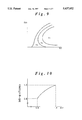
- FIG. 10 is a graph showing the relationship between the slip ratio etr and the lock-up clutch efficiency ⁇ ;
- FIG. 11 is a flow chart showing the procedure for computing the target engine output torque.
- FIG. 12 is a flow chart showing the procedure for computing the pressure PthB that is to be applied to the lock-up clutch.
- the motor vehicle to which the present invention is applied comprises an internal combustion engine 1, a power transmission system 2, a torque converter 3, incorporated with a lock-up clutch, interposed between the output shaft of the engine 1 and the input shaft of the power transmission system 2, and an ECU 5 for producing control signals for controlling the fuel injection unit and the throttle control unit of the engine 1, a control unit for the lock-up clutch 4, and a control unit for changing the gear ratio of the power transmission system 2.
- the ECU 5 receives data signals indicating the operating conditions of the vehicle such as the accelerator pedal stroke, the throttle opening angle, the vehicle speed and the rotational speed of the engine.
- the torque converter 3 and the lock-up clutch 4 are connected in parallel with each other in the path of power transmission, and can therefore individually and jointly transmit torque between the engine 1 and the power transmission system 2.
- the arithmetic computation unit of the ECU 5 conducts arithmetic operations as outlined in the flow chart of FIG. 2 to produce various control signals.
- a target drive force (traction) F is computed in step 1.
- the target drive force F is given as a mathematical function of the accelerator pedal stroke AP and the vehicle speed (rotational speed of the non-driven wheels) NV or given by
- This mathematical function may be based on a simple algebraic formula or other sophisticated techniques such as the fuzzy estimation theory.
- step 2 the gear ratio or the shift position that would achieve an minimum fuel consumption under the current operating conditions is determined by taking into account the efficiency of the torque converter 3.
- the optimum gear ratio is determined so as to satisfy the relationship between the engine torque and the engine rotational speed at the relevant point on the curve of optimum fuel consumption (BSFC) given in FIG. 3.
- BSFC optimum fuel consumption
- TE the engine torque
- TV the drive shaft torque
- R the gear ratio
- NE the engine rotational speed
- r the effective radius of the tires.
- the contour graph of FIG. 3 is drawn by connecting points of identical fuel consumption, and the curve of optimum fuel consumption (BSFC) which is given by low regions in the graph can be approximated by the following formula:
- the ideal gear ratio R can be expressed as follows: ##EQU2##
- the gear ratio R may be selected so that the fuel cut mode be preferentially selected during deceleration.
- the fuel cut mode involves an extremely lean condition or a total elimination of fuel supply.
- the gear ratio may be forced to a value which produces such a fuel cut condition. Thereby, a favorable fuel economy can be accomplished.
- the torque converter efficiency and the lock-up clutch efficiency are computed in the following steps.
- the values of the toque converter slip ratio etr ( BT/NE) at the shift position Sh which is closest to the ideal gear ratio R (based on the assumption that the slip ratio of the torque converter is zero) obtained from the above equation, and at the upper and lower adjacent shift positions Sh-1 and Sh+1 from an inverse map which is described hereinafter, and the shift position that will produce the optimum torque converter efficiency is determined by comparing the three values of the toque converter slip ratio.
- the values of the toque converter slip ratio may be determined for the computed ideal gear ratio and at the upper and lower adjacent gear ratios which are higher and lower by a prescribed gear ratio increment R 0 , respectively, so that the optimum gear ratio may be obtained by comparing the values of the toque converter slip ratio at these three different gear ratios either through a selection process or by interpolation. More specifically, ##EQU3## where Tpm is the pump absorption torque, Tau is the pump capacity, TTR is the torque converter transmission torque, k is the torque ratio, and NT is the pump rotational speed.
- FIG. 4 shows the relationship between the pump capacity Tau and the torque converter slip ratio etr
- FIG. 5 shows the relationship between the torque converter slip ratio etr and the torque ratio k
- FIG. 6 shows the relationship between the torque converter slip ratio etr and (TTR ⁇ 10 6 /NT 2 ).
- the torque converter slip ratio inverse map illustrated in FIG. 6 is thus obtained from the maps of Tau and k for etr so that the torque converter slip ratio etr can be readily obtained when the torque converter transmission torque TTR and the turbine rotational speed NT are given.
- the pressure applied to the lock-up clutch 4 is computed from the throttle opening angle ⁇ th .
- the torque converter transmission torque TTR is computed from the lock-up clutch transmission torque TLC and the turbine torque TT.
- the mark " ⁇ ” used in FIG. 3 indicates the ideal gear ratio R obtained from Equation (1)
- the mark “.increment.” used in FIG. 6 indicates the lower speed shift position or the higher gear ratio which is higher than the ideal gear ratio by one increment.
- the torque converter slip ratios corresponding to these gear ratios “ ⁇ ” and “.increment.” are indicated by “ ⁇ ” and " ⁇ ”, respectively, in FIG. 6.
- the corresponding torque converter efficiencies are indicated in FIG. 7. In this particular case, in terms of the torque converter efficiency, the gear ratio which is one increment to the lower speed range from the ideal gear ratio is determined to be optimum.
- step 3 the lock-up clutch efficiency is computed.
- TLC lock-up clutch transmission torque
- FIG. 8 The possible conditions of the lock-up clutch are illustrated in FIG. 8.
- the condition of the lock-up clutch is determined by the lock-up clutch actuation signal produced from the arithmetic unit of the ECU, and the central and right hand side ON regions differ from each other in the condition of the capacity control valve, the right hand side ON region corresponding to a tighter engagement of the lock-up clutch.
- the actual lock-up clutch efficiency B is determined as illustrated in FIG.
- step 4 the final shift position is determined.
- the relationship between the torque converter slip ratio etr and the lock-up clutch efficiency ⁇ is shown in FIG. 10.
- the optimum gear ratio is determined to be the one which is one increment on the lower speed side from the ideal gear ratio R. Therefore, the values of the torque converter slip ratio etr at the shift position Sh corresponding to the ideal gear ratio R and at the shift positions which are immediately above and below this shift position (Sh+1 and Sh-1) from the inverse map are obtained from the inverse map, and one of the shift positions is selected which provides the optimum torque converter slip ratio etr and lock-up clutch efficiency ⁇ .
- step 5 the target engine torque is computed.
- the target engine torque TECMD can be obtained according to the flow given in FIG. 11. First of all, the target engine torque TECMD is determined from the target drive shaft torque TDSOBJ, and the gear ratio IGEAR computed from the final shift position determined in step 4 (step 11). Then, it is determined if the on/off switching valve Aso1 of the lock-up clutch is on or off (step 12). If this valve is off, the lock-up clutch transmission torque TLC is reduced to zero as discussed earlier (step 13).
- TTR ⁇ 10 6 /NT 2 is then substituted into XetrW (step 14), and the value of XetrW is compared with a prescribed value Xetr0.
- the value Xetr0 is a threshold value which determines which of two halves of the torque converter inversion map should be used depending on the magnitude of XetrW. If XetrW>Xetr0, as it means that the engine of the vehicle is idling or the vehicle is at a start up condition involving a low speed and a high engine torque, the first inversion map ertCMDW involving a larger range with coarser increments is selected so as to achieve a low torque converter slip ratio (step 16).
- the second inversion map ertCMDN involving a smaller range with fine increments is selected after substituting TTR ⁇ 10 6 /NT 2 is into XetrN (step 17) as it is likely that there are large changes in the torque converter slip ratio (step 18).
- the target torque ratio KTRCMD is looked up (step 19), and the target engine torque TECMD is computed as TTCMD/(KTRCMD+TLC) (step 20).
- step 21 If Aso1 is on in step 12, as it means that TLC is not equal to zero, it is determined if the capacity control valve Bso1 is on or off (step 21). If Bso1 is off, the PthB pressure is computed for each of the shift positions according to the subroutine given in FIG. 12 (step 22). The lock-up clutch transmission torque TLC is looked up from the TLC-PthB pressure map (lock-up clutch being in the loose condition) (step 23). TLN is then adjusted and substituted by TLCN so as to account for a delay in the operation of the lock-up clutch (step 29).
- a lock-up clutch is known to demonstrate a certain time delay from the time a control signal is applied thereto and to the time the state of the lock-up clutch synchronizes with the control signal. To account for this delay, the lock-up clutch transmission torque TLC is treated as involving a first-order time delay. The modified lock-up clutch transmission torque TLCN is compared with the target turbine torque TTCMD (step 24). Thus, the transient behavior of the lock-up clutch is accurately accounted for, and it contributes to accurate determination of the engine torque.
- the above described procedure corresponds to the procedure for computing the torque converter transmission torque TTR, and determines which of the two conditions is applicable depending on how the torque is transmitted by the torque converter 3 and the lock-up clutch 4. If it is determined that TTCMD ⁇ TLC, it means that the lock-up clutch is tightly engaged. The lock-up clutch is otherwise under the loose condition or the semi-tight condition.
- step 24 If a lock-up clutch loose or semi-tight condition (TTCMD>TLCN) is detected in step 24, the target turbine torque TTCMD is computed as TTCMD-TLCN (step 25), and the program flow advances to step 14. If Bso1 is detected to be on in step 21, it is determined if the lock-up clutch is in tight or semi-tight condition and if the condition mode for Bso1 is feedback control or leaned data control depending on if Bso1 is fully open or not (step 26). If Bso1 is determined to be fully open, the PthB pressure is computed for each shift position according to the subroutine given in FIG. 12 (step 27), an the lock-up clutch transmission torque TLC is looked up from the TLC-PthB pressure map for the lock-up tight and semi-tight conditions (step 28) before the program flow advances to steps 29 and 24.
- step 26 If it is determined that Bso1 is not fully open in step 26, it means that the feedback control or the learned data control at the third or fourth shift position is currently in progress, and the current shift position is determined (step 30). If the third shift position is detected, the target torque converter slip ratio etrCMD is set to 0.98 (step 31). Otherwise, the target torque converter slip ratio etrCMD is set to 0.96 (step 32). This is because the control for keeping the lock-up clutch capacity TCL fixed will also keep the torque ratio fixed.
- step 24 If the result of the determination step in step 24 is "yes", or steps 31 or 32 has been passed through, as it can be assumed that a smooth torque transmission without any slippage has been in progress substantially only with the lock-up clutch, TLN is then adjusted and substituted by TLCN in step 34, similarly as was done in step 29, the target engine torque TECMD is set to be equal to the target turbine torque TTCMD (step 34).
Landscapes
- Engineering & Computer Science (AREA)
- General Engineering & Computer Science (AREA)
- Mechanical Engineering (AREA)
- Control Of Fluid Gearings (AREA)
- Control Of Transmission Device (AREA)
- Control Of Driving Devices And Active Controlling Of Vehicle (AREA)
Abstract
In a control system for controlling motor vehicles in such a manner that the drive force of the vehicle is determined by the accelerator pedal stroke and the vehicle speed, the fuel consumption is minimized by appropriately selecting the gear ratio of the power transmission system under each current operating condition. In particular, the present invention accounts for the slip ratio of the lock-up clutch as well as the transmission efficiency of the torque converter by noting the fact that the lock-up clutch operates under semi-tight conditions as well as under tight and loose conditions.
Description
The present invention relates to a control system for motor vehicles, and in particular to a control system for controlling motor vehicles equipped with a power transmission system combining a torque converter and a lock-up clutch.
To maximize the fuel efficiency of motor vehicles equipped with torque converters, it has been increasingly preferred to install a lock-up clutch which substantially rigidly engages the torque converter to positively prevent slippage of the torque converter. With regard to such motor vehicles, it was previously proposed in Japanese patent laid-open publication No. 5-262169 to compute a target output torque of the driven road wheels (axle torque) according to the current vehicle speed and the given throttle opening of the internal combustion engine of the vehicle, and to control the gear ratio of the power transmission system and the throttle opening of the engine so as to achieve the target output torque by taking into account the operating condition of the lock-up clutch.
A lock-up clutch is known to demonstrate partially engaged conditions involving varying degrees of slippage depending on the operating condition of the motor vehicle. However, this previously proposed control system is designed on the assumption that the lock-up clutch is either fully engaged or fully disengaged, and is therefore not capable of performing in an optimum fashion when the vehicle is operating under conditions in which the lock-up clutch is partially engaged in varying degrees.
In view of such problems of the prior art, a primary object of the present invention is to provide a control system for controlling motor vehicles equipped with a power transmission system combining a torque converter and a lock-up clutch which can operate in an optimum fashion even when the lock-up clutch is partially engaged.
A second object of the present invention is to improve the previously proposed control system for controlling motor vehicles equipped with a power transmission system combining a torque converter and a lock-up clutch so that a significant improvement can be made in fuel economy.
According to the present invention, these and other objects can be accomplished by providing a control system for a motor vehicle including a power source, a power transmission system having a gear train of a variable gear ratio, and a torque converter, equipped with a lock-up clutch, connected between the power source and the power transmission system, comprising: capacity control means for changing a transmission capacity of the lock-up clutch according to a current operating condition of the motor vehicle; efficiency computing means for computing transmission efficiencies of the torque converter and the lock-up clutch according to the current operating condition of the motor vehicle; gear ratio computing means for computing an optimum gear ratio for achieving an optimum fuel economy under the current operating condition; and optimum gear ratio selecting means for selecting an optimum gear ratio according to results of computation by the efficiency computing means and the gear ratio computing means.
Thus, even when the lock-up clutch is only partially engaged, and therefore involves a certain amount of slippage, it is possible to accurately compute the optimum gear ratio that would minimize the fuel consumption under each combination of operating conditions by computing the current transmission efficiency of the lock-up clutch, and taking into account the current slip ratio of the torque converter. Typically, the torque converter consists of a fluid torque converter.
According to a preferred embodiment of the present invention, the transmission efficiency of the torque converter is determined from a transmission torque and a rotational speed of the torque converter, and the transmission efficiency of the lock-up clutch is determined by a value indicating an operating condition of the capacity control means. Preferably, the control system further comprises target drive force computing means for computing a target drive force value of power output control means of the power source according to the gear ratio selected by the optimum gear ratio selecting means, and the transmission efficiencies of the torque converter and the lock-up clutch. To optimize the operating condition of the vehicle, it is preferable if the transmission efficiency of the torque converter is determined by the efficiency computing means for a plurality of different drive forces.
Now the present invention is described in the following with reference to the appended drawings, in which:
FIG. 1 is a schematic block diagram showing an essential part the motor vehicle to which the present invention is applied;
FIG. 2 is a flow chart showing the basic steps of computing various control signals according to the present invention;
FIG. 3 is a graph showing the dependence of fuel consumption on the output torque TE and the rotational speed NE of the engine;
FIG. 4 is a graph showing the relationship between the slip ratio etr and the pump capacity Tau of the torque converter;
FIG. 5 is a graph showing the relationship between the slip ratio etr and the torque ratio k of the torque converter;
FIG. 6 is a graph showing the relationship between the slip ratio etr and TTR·106 /NT2 of the torque converter;
FIG. 7 is a graph showing the relationship between the slip ratio etr and the efficiency of the torque converter;
FIG. 8 is a graph showing the dependence of the state of the lock-up clutch on the throttle opening θth of the engine and the vehicle speed NV;
FIG. 9 is a graph showing the dependence of the lock-up clutch efficiency η on the throttle opening θth of the engine and the vehicle speed NV;
FIG. 10 is a graph showing the relationship between the slip ratio etr and the lock-up clutch efficiency η;
FIG. 11 is a flow chart showing the procedure for computing the target engine output torque; and
FIG. 12 is a flow chart showing the procedure for computing the pressure PthB that is to be applied to the lock-up clutch.
Referring to FIG. 1, the motor vehicle to which the present invention is applied comprises an internal combustion engine 1, a power transmission system 2, a torque converter 3, incorporated with a lock-up clutch, interposed between the output shaft of the engine 1 and the input shaft of the power transmission system 2, and an ECU 5 for producing control signals for controlling the fuel injection unit and the throttle control unit of the engine 1, a control unit for the lock-up clutch 4, and a control unit for changing the gear ratio of the power transmission system 2. The ECU 5 receives data signals indicating the operating conditions of the vehicle such as the accelerator pedal stroke, the throttle opening angle, the vehicle speed and the rotational speed of the engine. The torque converter 3 and the lock-up clutch 4 are connected in parallel with each other in the path of power transmission, and can therefore individually and jointly transmit torque between the engine 1 and the power transmission system 2.
The arithmetic computation unit of the ECU 5 conducts arithmetic operations as outlined in the flow chart of FIG. 2 to produce various control signals. First of all, a target drive force (traction) F is computed in step 1. The target drive force F is given as a mathematical function of the accelerator pedal stroke AP and the vehicle speed (rotational speed of the non-driven wheels) NV or given by
F=F(AP,NV).
This mathematical function may be based on a simple algebraic formula or other sophisticated techniques such as the fuzzy estimation theory.
In step 2, the gear ratio or the shift position that would achieve an minimum fuel consumption under the current operating conditions is determined by taking into account the efficiency of the torque converter 3. Initially, by assuming that the slip ratio is substantially zero (as normally would be the case with the manual power transmission system), the optimum gear ratio is determined so as to satisfy the relationship between the engine torque and the engine rotational speed at the relevant point on the curve of optimum fuel consumption (BSFC) given in FIG. 3. ##EQU1## where TE is the engine torque, TV is the drive shaft torque, R is the gear ratio, NE is the engine rotational speed, and r is the effective radius of the tires. The contour graph of FIG. 3 is drawn by connecting points of identical fuel consumption, and the curve of optimum fuel consumption (BSFC) which is given by low regions in the graph can be approximated by the following formula:
TE=a·NE+b
where a and b are appropriately selected constants. Based on these relationships, the ideal gear ratio R can be expressed as follows: ##EQU2## In a vehicle engine control system using a fuel cut mode (F/C), the gear ratio R may be selected so that the fuel cut mode be preferentially selected during deceleration. Typically, the fuel cut mode involves an extremely lean condition or a total elimination of fuel supply. In other words, the gear ratio may be forced to a value which produces such a fuel cut condition. Thereby, a favorable fuel economy can be accomplished.
Then, the torque converter efficiency and the lock-up clutch efficiency are computed in the following steps. The values of the toque converter slip ratio etr (=BT/NE) at the shift position Sh which is closest to the ideal gear ratio R (based on the assumption that the slip ratio of the torque converter is zero) obtained from the above equation, and at the upper and lower adjacent shift positions Sh-1 and Sh+1 from an inverse map which is described hereinafter, and the shift position that will produce the optimum torque converter efficiency is determined by comparing the three values of the toque converter slip ratio. If the power transmission system is capable of changing the gear ratio in a continuous manner, the values of the toque converter slip ratio may be determined for the computed ideal gear ratio and at the upper and lower adjacent gear ratios which are higher and lower by a prescribed gear ratio increment R0, respectively, so that the optimum gear ratio may be obtained by comparing the values of the toque converter slip ratio at these three different gear ratios either through a selection process or by interpolation. More specifically, ##EQU3## where Tpm is the pump absorption torque, Tau is the pump capacity, TTR is the torque converter transmission torque, k is the torque ratio, and NT is the pump rotational speed.
FIG. 4 shows the relationship between the pump capacity Tau and the torque converter slip ratio etr, FIG. 5 shows the relationship between the torque converter slip ratio etr and the torque ratio k, and FIG. 6 shows the relationship between the torque converter slip ratio etr and (TTR·106 /NT2). The torque converter slip ratio inverse map illustrated in FIG. 6 is thus obtained from the maps of Tau and k for etr so that the torque converter slip ratio etr can be readily obtained when the torque converter transmission torque TTR and the turbine rotational speed NT are given.
Following is an example of the procedure for computing the values of the torque converter slip ratio etr when the lock-up clutch 4 is "loose", "semi-tight" and "tight" according to the turbine torque TT and the turbine rotational speed NT at the downstream end of the torque converter 3 and the lock-up clutch 4. It is assumed that the lock-up clutch is controlled both by an on-off switching valve and a capacity control valve. The "loose" condition is produced when only the on-off switching valve is opened, and the torque converter supplements or makes up for the deficiency of the lock-up clutch. The "semi-tight" and "tight" conditions of the lock-up clutch are produced by partially and completely opening the capacity control valve, respectively, in addition to opening the on-off switching valve.
The relationships between the turbine torque TT, the lock-up clutch transmission torque TLC, and the torque converter transmission torque TTR are computed in the following manner.
(1) The pressure applied to the lock-up clutch 4 is computed from the throttle opening angle θth.
PthB=PthB(θ.sub.th)
(2) The lock-up clutch transmission torque TLC is computed from the pressure applied to the lock-up clutch 4.
TLC=TLC(PthB)
(3) The torque converter transmission torque TTR is computed from the lock-up clutch transmission torque TLC and the turbine torque TT.
TTR=TT-TLC
When the lock-up clutch 4 is tightly engaged, TTR<0, and the necessary torque is transmitted solely by the lock-up clutch.
TE=TLC=TT, and NE-NT Hence, etr=1.
When TTR≧0, etr is obtained from the torque converter inverse map (FIG. 6), or
etr=f.sup.1 (TTR·10.sup.6 /NT.sup.2)
The mark "▪" used in FIG. 3 indicates the ideal gear ratio R obtained from Equation (1), and the mark ".increment." used in FIG. 6 indicates the lower speed shift position or the higher gear ratio which is higher than the ideal gear ratio by one increment. The torque converter slip ratios corresponding to these gear ratios "▪" and ".increment." are indicated by "" and "∘", respectively, in FIG. 6. The corresponding torque converter efficiencies are indicated in FIG. 7. In this particular case, in terms of the torque converter efficiency, the gear ratio which is one increment to the lower speed range from the ideal gear ratio is determined to be optimum.
In step 3, the lock-up clutch efficiency is computed. At this point, some explanation on the lock-up clutch transmission torque TLC may be in order. The possible conditions of the lock-up clutch are illustrated in FIG. 8. The condition of the lock-up clutch is determined by the lock-up clutch actuation signal produced from the arithmetic unit of the ECU, and the central and right hand side ON regions differ from each other in the condition of the capacity control valve, the right hand side ON region corresponding to a tighter engagement of the lock-up clutch. Thus, according to the lock-up clutch actuation signal, the actual lock-up clutch efficiency B is determined as illustrated in FIG. 9 in which η1 and η2 indicate the tight and semi-tight conditions of the lock-up clutch while η3 indicates the loose condition of the lock-up clutch. According to the lock-up clutch efficiency, the actual lock-up clutch transmission torque TLC is determined. The slight discrepancy between the signals of FIG. 8 and the efficiencies of FIG. 9 is attributed to the insufficiency of the PthB pressure particularly in the smaller throttle opening angle side.
In step 4, the final shift position is determined. The relationship between the torque converter slip ratio etr and the lock-up clutch efficiency η is shown in FIG. 10. In this particular case, the optimum gear ratio is determined to be the one which is one increment on the lower speed side from the ideal gear ratio R. Therefore, the values of the torque converter slip ratio etr at the shift position Sh corresponding to the ideal gear ratio R and at the shift positions which are immediately above and below this shift position (Sh+1 and Sh-1) from the inverse map are obtained from the inverse map, and one of the shift positions is selected which provides the optimum torque converter slip ratio etr and lock-up clutch efficiency η.
In step 5, the target engine torque is computed. The target engine torque TECMD can be obtained according to the flow given in FIG. 11. First of all, the target engine torque TECMD is determined from the target drive shaft torque TDSOBJ, and the gear ratio IGEAR computed from the final shift position determined in step 4 (step 11). Then, it is determined if the on/off switching valve Aso1 of the lock-up clutch is on or off (step 12). If this valve is off, the lock-up clutch transmission torque TLC is reduced to zero as discussed earlier (step 13).
TTR·106 /NT2 is then substituted into XetrW (step 14), and the value of XetrW is compared with a prescribed value Xetr0. The value Xetr0 is a threshold value which determines which of two halves of the torque converter inversion map should be used depending on the magnitude of XetrW. If XetrW>Xetr0, as it means that the engine of the vehicle is idling or the vehicle is at a start up condition involving a low speed and a high engine torque, the first inversion map ertCMDW involving a larger range with coarser increments is selected so as to achieve a low torque converter slip ratio (step 16). Conversely, if XetrW<Xetr0, as it means that the vehicle is in a cruising condition involving a high speed and a low engine torque, the second inversion map ertCMDN involving a smaller range with fine increments is selected after substituting TTR·106 /NT2 is into XetrN (step 17) as it is likely that there are large changes in the torque converter slip ratio (step 18). By thus providing two different versions of the inverse map, it is possible to achieve both quick response and high accuracy.
Thereafter, the target torque ratio KTRCMD is looked up (step 19), and the target engine torque TECMD is computed as TTCMD/(KTRCMD+TLC) (step 20).
If Aso1 is on in step 12, as it means that TLC is not equal to zero, it is determined if the capacity control valve Bso1 is on or off (step 21). If Bso1 is off, the PthB pressure is computed for each of the shift positions according to the subroutine given in FIG. 12 (step 22). The lock-up clutch transmission torque TLC is looked up from the TLC-PthB pressure map (lock-up clutch being in the loose condition) (step 23). TLN is then adjusted and substituted by TLCN so as to account for a delay in the operation of the lock-up clutch (step 29). A lock-up clutch is known to demonstrate a certain time delay from the time a control signal is applied thereto and to the time the state of the lock-up clutch synchronizes with the control signal. To account for this delay, the lock-up clutch transmission torque TLC is treated as involving a first-order time delay. The modified lock-up clutch transmission torque TLCN is compared with the target turbine torque TTCMD (step 24). Thus, the transient behavior of the lock-up clutch is accurately accounted for, and it contributes to accurate determination of the engine torque.
The above described procedure corresponds to the procedure for computing the torque converter transmission torque TTR, and determines which of the two conditions is applicable depending on how the torque is transmitted by the torque converter 3 and the lock-up clutch 4. If it is determined that TTCMD≦TLC, it means that the lock-up clutch is tightly engaged. The lock-up clutch is otherwise under the loose condition or the semi-tight condition.
If a lock-up clutch loose or semi-tight condition (TTCMD>TLCN) is detected in step 24, the target turbine torque TTCMD is computed as TTCMD-TLCN (step 25), and the program flow advances to step 14. If Bso1 is detected to be on in step 21, it is determined if the lock-up clutch is in tight or semi-tight condition and if the condition mode for Bso1 is feedback control or leaned data control depending on if Bso1 is fully open or not (step 26). If Bso1 is determined to be fully open, the PthB pressure is computed for each shift position according to the subroutine given in FIG. 12 (step 27), an the lock-up clutch transmission torque TLC is looked up from the TLC-PthB pressure map for the lock-up tight and semi-tight conditions (step 28) before the program flow advances to steps 29 and 24.
If it is determined that Bso1 is not fully open in step 26, it means that the feedback control or the learned data control at the third or fourth shift position is currently in progress, and the current shift position is determined (step 30). If the third shift position is detected, the target torque converter slip ratio etrCMD is set to 0.98 (step 31). Otherwise, the target torque converter slip ratio etrCMD is set to 0.96 (step 32). This is because the control for keeping the lock-up clutch capacity TCL fixed will also keep the torque ratio fixed.
If the result of the determination step in step 24 is "yes", or steps 31 or 32 has been passed through, as it can be assumed that a smooth torque transmission without any slippage has been in progress substantially only with the lock-up clutch, TLN is then adjusted and substituted by TLCN in step 34, similarly as was done in step 29, the target engine torque TECMD is set to be equal to the target turbine torque TTCMD (step 34).
Thus, according to the present invention, it is possible to accurately estimate the torque transmission efficiency by accurately detecting the slip ratio of the torque converter and the engagement condition of the lock-up clutch. Therefore, it is possible to conform the actual drive force to the target drive force in a highly accurate manner, and a substantial gain can be achieved in saving fuel consumption of the engine.
Although the present invention has been described in terms of a preferred embodiment thereof, it is obvious to a person skilled in the art that various alterations and modifications are possible without departing from the scope of the present invention which is set forth in the appended claims.
Claims (6)
1. A control system for a motor vehicle including a power source, a power transmission system having a gear train of a variable gear ratio, and a torque converter, equipped with a lock-up clutch, connected between said power source and said power transmission system, comprising:
capacity control means for changing a transmission capacity of said lock-up clutch according to a current operating condition of said motor vehicle;
efficiency computing means for computing transmission efficiencies of said torque converter and said lock-up clutch according to said current operating condition of said motor vehicle;
gear ratio computing means for computing an optimum gear ratio for achieving an optimum fuel economy under said current operating condition; and
optimum gear ratio selecting means for selecting an optimum gear ratio according to results of computation by said efficiency computing means and said gear ratio computing means.
2. A control system for a motor vehicle according to claim 1, wherein said torque converter consists of a fluid torque converter.
3. A control system for a motor vehicle according to claim 1, wherein said transmission efficiency of said torque converter is determined from a transmission torque and a rotational speed of said torque converter.
4. A control system for a motor vehicle according to claim 1, wherein said transmission efficiency of said lock-up clutch is determined by a value indicating an operating condition of said capacity control means.
5. A control system for a motor vehicle according to claim 1, further comprising target drive force computing means for computing a target drive force value of power output control means of said power source according to said gear ratio selected by said optimum gear ratio selecting means, and said transmission efficiencies of said torque converter and said lock-up clutch.
6. A control system for a motor vehicle according to claim 5, wherein said transmission efficiency of said torque converter is determined by said efficiency computing means for a plurality of different drive forces of said power source.
Applications Claiming Priority (2)
| Application Number | Priority Date | Filing Date | Title |
|---|---|---|---|
| JP6-338031 | 1994-12-26 | ||
| JP6338031A JPH08178054A (en) | 1994-12-26 | 1994-12-26 | Car control equipment |
Publications (1)
| Publication Number | Publication Date |
|---|---|
| US5637052A true US5637052A (en) | 1997-06-10 |
Family
ID=18314286
Family Applications (1)
| Application Number | Title | Priority Date | Filing Date |
|---|---|---|---|
| US08/577,938 Expired - Fee Related US5637052A (en) | 1994-12-26 | 1995-12-22 | Control system for motor vehicles equipped with a torque converter and a lock-up clutch |
Country Status (2)
| Country | Link |
|---|---|
| US (1) | US5637052A (en) |
| JP (1) | JPH08178054A (en) |
Cited By (24)
| Publication number | Priority date | Publication date | Assignee | Title |
|---|---|---|---|---|
| EP0860633A1 (en) * | 1997-02-17 | 1998-08-26 | ZF FRIEDRICHSHAFEN Aktiengesellschaft | Method of controlling a torque converter lockup clutch during vehicle startoff |
| EP0926402A1 (en) * | 1997-12-22 | 1999-06-30 | Van Doorne's Transmissie B.V. | Power train |
| US6022294A (en) * | 1997-09-17 | 2000-02-08 | Honda Giken Kogyo Kabushiki Kaisha | Lock-up control device |
| US6039675A (en) * | 1997-09-19 | 2000-03-21 | Nissan Motor Co., Ltd. | Slip control system for torque converter |
| US6314357B1 (en) * | 1997-10-01 | 2001-11-06 | Honda Giken Kogyo Kabushiki Kaisha | Lock-up control device |
| US6454676B1 (en) * | 2000-05-12 | 2002-09-24 | Mitsubishi Denki Kabushiki Kaisha | Control system for internal combustion engine equipped with automatic transmission |
| US20030130088A1 (en) * | 2000-05-11 | 2003-07-10 | Peter Schiele | Control system for a motor vehicle transmission comprising torque converter or a hydrodynamic clutch |
| EP1273497A3 (en) * | 2001-07-02 | 2003-08-20 | Robert Bosch Gmbh | Method for preventing tampering of an automotive electronic control unit |
| EP1158220A3 (en) * | 2000-05-26 | 2004-02-04 | Honda Giken Kogyo Kabushiki Kaisha | Road surface gradient detecting apparatus |
| US6746368B2 (en) * | 2000-05-16 | 2004-06-08 | Nissan Motor Co., Ltd. | Vehicle speed control system for automotive vehicle |
| EP1498297A1 (en) * | 2003-07-15 | 2005-01-19 | Miyama, Inc. | Evaluation system/method for vehicle fuel consumption |
| US20050027423A1 (en) * | 2003-07-18 | 2005-02-03 | Katsuaki Minami | Ealuation system for vehicle operating conditions and evaluation method thereof |
| WO2006079373A1 (en) * | 2005-01-28 | 2006-08-03 | Voith Turbo Gmbh & Co. Kg | Method for controlling a gearbox in the drive train of a vehicle, in particular during switching from an at least partially hydrodynamic power transmission to a mechanical power transmission |
| US20100036574A1 (en) * | 2008-08-08 | 2010-02-11 | Honda Motor Co., Ltd. | Controlling a Throttle for Fuel Cut Acquisition |
| CN101240844B (en) * | 2007-02-06 | 2013-07-24 | 黄兆焕 | Motor vehicle automatic step speed variator speed-changing method |
| US20150377351A1 (en) * | 2013-02-18 | 2015-12-31 | Nissan Motor Co., Ltd. | Shift control system for automatic transmission |
| US20170167601A1 (en) * | 2015-12-09 | 2017-06-15 | Hyundai Motor Company | Shifting control method for vehicle |
| CN107218384A (en) * | 2016-03-22 | 2017-09-29 | 丰田自动车株式会社 | The speed-change control device of vehicle |
| US11014982B2 (en) | 2017-02-07 | 2021-05-25 | Janssen Biotech, Inc. | Anti-TNF antibodies, compositions, and methods for the treatment of active ankylosing spondylitis |
| US11041020B2 (en) | 2017-01-30 | 2021-06-22 | Janssen Biotech, Inc. | Methods for the treatment of active Psoriatic Arthritis |
| JP2021139049A (en) * | 2015-11-18 | 2021-09-16 | ア−カム アーベー | Device for forming three-dimensional object |
| US20220306072A1 (en) * | 2021-03-25 | 2022-09-29 | Honda Motor Co., Ltd. | Vehicle control device |
| US11780911B2 (en) | 2019-05-23 | 2023-10-10 | Janssen Biotech, Inc. | Method of treating inflammatory bowel disease with a combination therapy of antibodies to IL-23 and TNF alpha |
| US12258393B2 (en) | 2020-05-21 | 2025-03-25 | Janssen Biotech, Inc. | Method of treating inflammatory bowel disease with a combination therapy of antibodies to IL-23 and TNF alpha |
Families Citing this family (6)
| Publication number | Priority date | Publication date | Assignee | Title |
|---|---|---|---|---|
| US7822524B2 (en) | 2003-12-26 | 2010-10-26 | Toyota Jidosha Kabushiki Kaisha | Vehicular drive system |
| WO2010050016A1 (en) * | 2008-10-29 | 2010-05-06 | トヨタ自動車株式会社 | Control device for automatic transmission |
| US9701299B2 (en) * | 2014-02-27 | 2017-07-11 | GM Global Technology Operations LLC | System and method for controlling an engine based on a desired turbine power to account for losses in a torque converter |
| CN106195255B (en) * | 2016-07-06 | 2017-11-07 | 厦门大学 | Automatic catch wheel loader fluid torque-converter control method |
| CN112572405B (en) * | 2019-09-27 | 2022-04-15 | 比亚迪股份有限公司 | Method, device, storage medium, and vehicle for driving a vehicle |
| CN112124227A (en) * | 2020-09-28 | 2020-12-25 | 湖南行必达网联科技有限公司 | Intelligent gear shifting reminding system and method for vehicle |
Citations (3)
| Publication number | Priority date | Publication date | Assignee | Title |
|---|---|---|---|---|
| US4905544A (en) * | 1975-09-25 | 1990-03-06 | Ganoung David P | Powertrain control apparatus for improving fuel economy |
| JPH05262169A (en) * | 1992-03-19 | 1993-10-12 | Hitachi Ltd | Torque control method and apparatus for internal combustion engine and automobile |
| US5274553A (en) * | 1991-05-09 | 1993-12-28 | Eaton Corporation | Torque converter slip rate based skip power downshift control strategy |
-
1994
- 1994-12-26 JP JP6338031A patent/JPH08178054A/en active Pending
-
1995
- 1995-12-22 US US08/577,938 patent/US5637052A/en not_active Expired - Fee Related
Patent Citations (3)
| Publication number | Priority date | Publication date | Assignee | Title |
|---|---|---|---|---|
| US4905544A (en) * | 1975-09-25 | 1990-03-06 | Ganoung David P | Powertrain control apparatus for improving fuel economy |
| US5274553A (en) * | 1991-05-09 | 1993-12-28 | Eaton Corporation | Torque converter slip rate based skip power downshift control strategy |
| JPH05262169A (en) * | 1992-03-19 | 1993-10-12 | Hitachi Ltd | Torque control method and apparatus for internal combustion engine and automobile |
Cited By (35)
| Publication number | Priority date | Publication date | Assignee | Title |
|---|---|---|---|---|
| EP0860633A1 (en) * | 1997-02-17 | 1998-08-26 | ZF FRIEDRICHSHAFEN Aktiengesellschaft | Method of controlling a torque converter lockup clutch during vehicle startoff |
| US6022294A (en) * | 1997-09-17 | 2000-02-08 | Honda Giken Kogyo Kabushiki Kaisha | Lock-up control device |
| MY120052A (en) * | 1997-09-17 | 2005-08-30 | Honda Motor Co Ltd | Lock-up control device |
| US6039675A (en) * | 1997-09-19 | 2000-03-21 | Nissan Motor Co., Ltd. | Slip control system for torque converter |
| US6314357B1 (en) * | 1997-10-01 | 2001-11-06 | Honda Giken Kogyo Kabushiki Kaisha | Lock-up control device |
| EP0926402A1 (en) * | 1997-12-22 | 1999-06-30 | Van Doorne's Transmissie B.V. | Power train |
| US6785598B2 (en) * | 2000-05-11 | 2004-08-31 | Zf Friedrichshafen | Control system for a motor vehicle transmission comprising a torque converter or a hydrodynamic clutch |
| US20030130088A1 (en) * | 2000-05-11 | 2003-07-10 | Peter Schiele | Control system for a motor vehicle transmission comprising torque converter or a hydrodynamic clutch |
| US6454676B1 (en) * | 2000-05-12 | 2002-09-24 | Mitsubishi Denki Kabushiki Kaisha | Control system for internal combustion engine equipped with automatic transmission |
| US6746368B2 (en) * | 2000-05-16 | 2004-06-08 | Nissan Motor Co., Ltd. | Vehicle speed control system for automotive vehicle |
| EP1158220A3 (en) * | 2000-05-26 | 2004-02-04 | Honda Giken Kogyo Kabushiki Kaisha | Road surface gradient detecting apparatus |
| EP1273497A3 (en) * | 2001-07-02 | 2003-08-20 | Robert Bosch Gmbh | Method for preventing tampering of an automotive electronic control unit |
| EP1498297A1 (en) * | 2003-07-15 | 2005-01-19 | Miyama, Inc. | Evaluation system/method for vehicle fuel consumption |
| US20050027423A1 (en) * | 2003-07-18 | 2005-02-03 | Katsuaki Minami | Ealuation system for vehicle operating conditions and evaluation method thereof |
| US7072762B2 (en) * | 2003-07-18 | 2006-07-04 | Miyama, Inc. | Evaluation system for vehicle operating conditions and evaluation method thereof |
| WO2006079373A1 (en) * | 2005-01-28 | 2006-08-03 | Voith Turbo Gmbh & Co. Kg | Method for controlling a gearbox in the drive train of a vehicle, in particular during switching from an at least partially hydrodynamic power transmission to a mechanical power transmission |
| CN101240844B (en) * | 2007-02-06 | 2013-07-24 | 黄兆焕 | Motor vehicle automatic step speed variator speed-changing method |
| US20100036574A1 (en) * | 2008-08-08 | 2010-02-11 | Honda Motor Co., Ltd. | Controlling a Throttle for Fuel Cut Acquisition |
| US8630778B2 (en) * | 2008-08-08 | 2014-01-14 | Honda Motor Co., Ltd. | Controlling a throttle for fuel cut acquisition |
| US20150377351A1 (en) * | 2013-02-18 | 2015-12-31 | Nissan Motor Co., Ltd. | Shift control system for automatic transmission |
| US9371906B2 (en) * | 2013-02-18 | 2016-06-21 | Nissan Motor Co., Ltd. | Shift control system for automatic transmission |
| JP2021139049A (en) * | 2015-11-18 | 2021-09-16 | ア−カム アーベー | Device for forming three-dimensional object |
| US11623282B2 (en) | 2015-11-18 | 2023-04-11 | Arcam Ab | Additive manufacturing of three-dimensional articles |
| US20170167601A1 (en) * | 2015-12-09 | 2017-06-15 | Hyundai Motor Company | Shifting control method for vehicle |
| US9739370B2 (en) * | 2015-12-09 | 2017-08-22 | Hyundai Motor Company | Shifting control method for vehicle |
| CN107218384A (en) * | 2016-03-22 | 2017-09-29 | 丰田自动车株式会社 | The speed-change control device of vehicle |
| CN107218384B (en) * | 2016-03-22 | 2019-05-03 | 丰田自动车株式会社 | Transmission control device for vehicle |
| US11041020B2 (en) | 2017-01-30 | 2021-06-22 | Janssen Biotech, Inc. | Methods for the treatment of active Psoriatic Arthritis |
| US12122824B2 (en) | 2017-01-30 | 2024-10-22 | Janssen Biotech, Inc. | Anti-TNF antibodies, compositions, and methods for the treatment of active ankylosing spondylitis |
| US11014982B2 (en) | 2017-02-07 | 2021-05-25 | Janssen Biotech, Inc. | Anti-TNF antibodies, compositions, and methods for the treatment of active ankylosing spondylitis |
| US12291566B2 (en) | 2017-02-07 | 2025-05-06 | Janssen Biotech, Inc. | Anti-TNF antibodies, compositions, and methods for the treatment of active Ankylosing Spondylitis |
| US11780911B2 (en) | 2019-05-23 | 2023-10-10 | Janssen Biotech, Inc. | Method of treating inflammatory bowel disease with a combination therapy of antibodies to IL-23 and TNF alpha |
| US12258393B2 (en) | 2020-05-21 | 2025-03-25 | Janssen Biotech, Inc. | Method of treating inflammatory bowel disease with a combination therapy of antibodies to IL-23 and TNF alpha |
| US20220306072A1 (en) * | 2021-03-25 | 2022-09-29 | Honda Motor Co., Ltd. | Vehicle control device |
| US11745722B2 (en) * | 2021-03-25 | 2023-09-05 | Honda Motor Co., Ltd. | Vehicle control device |
Also Published As
| Publication number | Publication date |
|---|---|
| JPH08178054A (en) | 1996-07-12 |
Similar Documents
| Publication | Publication Date | Title |
|---|---|---|
| US5637052A (en) | Control system for motor vehicles equipped with a torque converter and a lock-up clutch | |
| US6440037B2 (en) | Control system for vehicle having continuously variable transmission | |
| US6736753B2 (en) | Vehicle drive control apparatus and method | |
| US6459978B2 (en) | Method and apparatus to control continuously variable transmission of motor vehicle | |
| US8392079B2 (en) | Vehicle, control method and control apparatus for vehicle | |
| US6757603B2 (en) | Slippage prevention apparatus of belt-drive continuously variable transmission for automotive vehicle | |
| JP2506630B2 (en) | CVT control method | |
| US20040144608A1 (en) | Fluid pressure control device for lock-up mechanism | |
| US8498789B2 (en) | Control apparatus and control method for drive source | |
| JPH049936B2 (en) | ||
| US5377562A (en) | Driven wheel torque control system | |
| US20100274460A1 (en) | Control apparatus and control method for power source | |
| JP2006336853A (en) | Vehicle starting clutch control device | |
| US7983826B2 (en) | Control apparatus and control method for drive source | |
| JP3565122B2 (en) | Creep force control device for automatic transmission for vehicles | |
| JP2924475B2 (en) | Control device for vehicle with automatic transmission | |
| JPS6387318A (en) | Control device for four-wheel drive vehicle | |
| KR100411117B1 (en) | Method of controlling acceleration for hybrid eletric vehicles | |
| JP4122585B2 (en) | Vehicle driving force control device | |
| JP3624668B2 (en) | Vehicle driving force control device | |
| JPH04316759A (en) | Control device for continuously variable transmission | |
| JP2541827B2 (en) | Controller for continuously variable transmission | |
| JPS632745A (en) | Continously variable transmission control vehicle | |
| JPH01224526A (en) | Control device of hydraulic clutch | |
| JP2007132238A (en) | Engine output control device for vehicle start |
Legal Events
| Date | Code | Title | Description |
|---|---|---|---|
| FEPP | Fee payment procedure |
Free format text: PAYOR NUMBER ASSIGNED (ORIGINAL EVENT CODE: ASPN); ENTITY STATUS OF PATENT OWNER: LARGE ENTITY |
|
| FPAY | Fee payment |
Year of fee payment: 4 |
|
| FPAY | Fee payment |
Year of fee payment: 8 |
|
| REMI | Maintenance fee reminder mailed | ||
| LAPS | Lapse for failure to pay maintenance fees | ||
| STCH | Information on status: patent discontinuation |
Free format text: PATENT EXPIRED DUE TO NONPAYMENT OF MAINTENANCE FEES UNDER 37 CFR 1.362 |
|
| FP | Lapsed due to failure to pay maintenance fee |
Effective date: 20090610 |