US563529A - wilson - Google Patents
wilson Download PDFInfo
- Publication number
- US563529A US563529A US563529DA US563529A US 563529 A US563529 A US 563529A US 563529D A US563529D A US 563529DA US 563529 A US563529 A US 563529A
- Authority
- US
- United States
- Prior art keywords
- column
- pillar
- view
- wilson
- section
- Prior art date
- Legal status (The legal status is an assumption and is not a legal conclusion. Google has not performed a legal analysis and makes no representation as to the accuracy of the status listed.)
- Expired - Lifetime
Links
- XEEYBQQBJWHFJM-UHFFFAOYSA-N Iron Chemical compound [Fe] XEEYBQQBJWHFJM-UHFFFAOYSA-N 0.000 description 4
- 238000010276 construction Methods 0.000 description 4
- 238000000034 method Methods 0.000 description 3
- 229910000831 Steel Inorganic materials 0.000 description 2
- 229910052742 iron Inorganic materials 0.000 description 2
- 239000010959 steel Substances 0.000 description 2
- 240000001973 Ficus microcarpa Species 0.000 description 1
- 238000006023 Wilson reaction Methods 0.000 description 1
- 230000001788 irregular Effects 0.000 description 1
Images


Classifications
-
- E—FIXED CONSTRUCTIONS
- E04—BUILDING
- E04B—GENERAL BUILDING CONSTRUCTIONS; WALLS, e.g. PARTITIONS; ROOFS; FLOORS; CEILINGS; INSULATION OR OTHER PROTECTION OF BUILDINGS
- E04B1/00—Constructions in general; Structures which are not restricted either to walls, e.g. partitions, or floors or ceilings or roofs
- E04B1/18—Structures comprising elongated load-supporting parts, e.g. columns, girders, skeletons
- E04B1/24—Structures comprising elongated load-supporting parts, e.g. columns, girders, skeletons the supporting parts consisting of metal
- E04B1/2403—Connection details of the elongated load-supporting parts
-
- Y—GENERAL TAGGING OF NEW TECHNOLOGICAL DEVELOPMENTS; GENERAL TAGGING OF CROSS-SECTIONAL TECHNOLOGIES SPANNING OVER SEVERAL SECTIONS OF THE IPC; TECHNICAL SUBJECTS COVERED BY FORMER USPC CROSS-REFERENCE ART COLLECTIONS [XRACs] AND DIGESTS
- Y10—TECHNICAL SUBJECTS COVERED BY FORMER USPC
- Y10T—TECHNICAL SUBJECTS COVERED BY FORMER US CLASSIFICATION
- Y10T403/00—Joints and connections
- Y10T403/34—Branched
- Y10T403/341—Three or more radiating members
- Y10T403/344—Plural pairs of axially aligned members
Definitions
- WITNESSES INVEN Ton A rronusnr UNITED STATES PATENT OFFI E.
- This invention relates to the construction of buildings in which iron or steel frames are employed, and the object thereof is to provide an improved method or system for connecting the columns or pillars and the beams or girders of such iron or steel frames, a further object being to provide a method of interlockingor connecting said columns or pillars and beams or girders, by which the use of bolts and nuts or rivets will be avoided, and by means of which, if any portion of the frame from any cause becomes loaded to breaking, the accident will be local and not affect the entire structure or those sections thereof adjacent to that portion which is injured; and with this and other objects in view the invention consists in the construction, combination, and arrangement of parts hereinafter described and claimed, and in the method of the operation thereof.
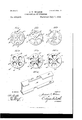
- Figure 1 represents a central vertical section of a portion of a ground column or pillar and an upper column or pillar mounted thereon, showing also one of the beams or girders in position, and vertical sections of others, the columns or pillars shown in this viewbein g what are known as side columns or pillars,'or those adapted to be placed in an outer wall, or'in the outer portion of the frame, and this view is also a section on the line 1 1 of Fig. 5; Fig.
- Fig. 2 a similar section of the upper end of the ground column or pillar and the lower end of the upper column or pillar mounted thereon, showing also two girders or beams in position, and the columns or pillars shown in this view are such as are known as central or"inside columns or pillars, and this view is also a section on the line 2 2 of Fig. l.
- Fig. 3 is a similar view of the upper portion of the ground column or pillar and the upper column or pillar mounted thereon, and the form of columns or pillars shown in this View being what are known as cornercolumns, and this viewis also a section on the line 3 3 of Fig. 6.
- Fig. 4 is a cross-section on the line 4 4 of Fig. 2; Fig.
- Fig. 6 a similar section on the line 6 6 of Fig. 3; Fig. 7, a bottom plan view of the upper column or pillar shown in Fig. 2; Fig. 8, a bottom plan view of the upper column or pillar shown in Fig. 1; Fig. 9, a bottom plan view of the upper column or pillar shown in Fig. 3.
- Fig. 10 is a plan view of the upper end of the lower column or pillar shown in Fig. 2; Fig. 11, a similar view of the lower column or pillar shown in Fig. 1; Fig. 12, a similar view of the lower column or pillar shown in Fig. 3, and Figs. 13 and 14 are perspective views of difierent forms of girders orbeams which are employed.
- A represents what is known as a base or ground column or pillar, and the upper end of this column or pillar is provided with a head Ct and a central vertical projection a, which is preferably irregular in form, as shown in Fig. 8, and the body portion of this head and column is preferably cut out or hollow.
- the beams or girders used in connection with this column are shown in Figs. 13 and 14, and designated by the letters B and D, respectively, and they are provided with depending pins 1) and d, which are adapted to enter corresponding holes in the head a and are placed in position upon the head a of the column A, as shown in Fig. 1.
- the girder D is also provided with top and bottom plates 61 and the upper plate is cut out, as shown at (1 and the girder B is provided with top and bottom plates b and with a vertical head 19 which is separated from the top plate I) by notches or recesses 19
- the upper column G the lower end of which is shown in Fig. 1, and a cross-section of which is shown in Fig. 5, and a bottom plan view of which is given in Fig.
- WITNESSES INVENTUH 054 /5 M f BY A TTORNEYJI no: mums rrrzn: cu. vnnvoumu. wnmnmon, p. c.
Landscapes
- Engineering & Computer Science (AREA)
- Architecture (AREA)
- Physics & Mathematics (AREA)
- Electromagnetism (AREA)
- Civil Engineering (AREA)
- Structural Engineering (AREA)
- Rod-Shaped Construction Members (AREA)
Description
(No Model.) 3 Sheets-Sheet 1.
. J. T. WILSON. CONSTRUCTION OF BUILDINGS. No. 563,529. Patented July 7, L896.
I w m f Q A Jw W A w c W J k a dW/TNESSES: [4/2 (flu Mbdel.) I 3 Sheets-Sheet 3 Y J. T. WILSON.
GONSTRUGTION 0F BUILDINGS.
Np. 563,529. Patented July 7, 1896.
WITNESSES: INVEN Ton A rronusnr UNITED STATES PATENT OFFI E.
JAMES THOMPSON WILSON, OF NEW YORK, N. Y.
CONSTRUCTION OF BUILDINGS.
SPECIFICATION forming part Of Letters Patent No. 563,529, dated July 7, 1896.
Application filed November 27, 1895. Serial No. 570,260. (No model.)
To all whom it may concern:
Be it known that I, JAMES THOMPSON WIL- SON, a subject of the Queen of Great Britain, and a resident of New York, in the county of New York and State of New York, have invented certain new and useful Improvements in the Construction of Buildings, of which the following is a specification, reference being had to the accompanying drawings, forming a part thereof, in which similar letters of reference indicate corresponding parts.
This invention relates to the construction of buildings in which iron or steel frames are employed, and the object thereof is to provide an improved method or system for connecting the columns or pillars and the beams or girders of such iron or steel frames, a further object being to provide a method of interlockingor connecting said columns or pillars and beams or girders, by which the use of bolts and nuts or rivets will be avoided, and by means of which, if any portion of the frame from any cause becomes loaded to breaking, the accident will be local and not affect the entire structure or those sections thereof adjacent to that portion which is injured; and with this and other objects in view the invention consists in the construction, combination, and arrangement of parts hereinafter described and claimed, and in the method of the operation thereof.
The invention is fully disclosed in the following specification, of which the accompanying drawings form a part, in which Figure 1 represents a central vertical section of a portion of a ground column or pillar and an upper column or pillar mounted thereon, showing also one of the beams or girders in position, and vertical sections of others, the columns or pillars shown in this viewbein g what are known as side columns or pillars,'or those adapted to be placed in an outer wall, or'in the outer portion of the frame, and this view is also a section on the line 1 1 of Fig. 5; Fig. 2, a similar section of the upper end of the ground column or pillar and the lower end of the upper column or pillar mounted thereon, showing also two girders or beams in position, and the columns or pillars shown in this view are such as are known as central or"inside columns or pillars, and this view is also a section on the line 2 2 of Fig. l. Fig. 3 is a similar view of the upper portion of the ground column or pillar and the upper column or pillar mounted thereon, and the form of columns or pillars shown in this View being what are known as cornercolumns, and this viewis also a section on the line 3 3 of Fig. 6. Fig. 4is a cross-section on the line 4 4 of Fig. 2; Fig.
'5, a similar section on the line 5 5 of Fig. 1;
Fig. 6, a similar section on the line 6 6 of Fig. 3; Fig. 7, a bottom plan view of the upper column or pillar shown in Fig. 2; Fig. 8, a bottom plan view of the upper column or pillar shown in Fig. 1; Fig. 9, a bottom plan view of the upper column or pillar shown in Fig. 3. Fig. 10 is a plan view of the upper end of the lower column or pillar shown in Fig. 2; Fig. 11, a similar view of the lower column or pillar shown in Fig. 1; Fig. 12, a similar view of the lower column or pillar shown in Fig. 3, and Figs. 13 and 14 are perspective views of difierent forms of girders orbeams which are employed.
Referring to Figs. 1 and 8, A represents what is known as a base or ground column or pillar, and the upper end of this column or pillar is provided with a head Ct and a central vertical projection a, which is preferably irregular in form, as shown in Fig. 8, and the body portion of this head and column is preferably cut out or hollow. The beams or girders used in connection with this column are shown in Figs. 13 and 14, and designated by the letters B and D, respectively, and they are provided with depending pins 1) and d, which are adapted to enter corresponding holes in the head a and are placed in position upon the head a of the column A, as shown in Fig. 1. The girder D is also provided with top and bottom plates 61 and the upper plate is cut out, as shown at (1 and the girder B is provided with top and bottom plates b and with a vertical head 19 which is separated from the top plate I) by notches or recesses 19 The upper column G, the lower end of which is shown in Fig. 1, and a cross-section of which is shown in Fig. 5, and a bottom plan view of which is given in Fig. 8, is enlarged so as to correspond with the head a, of the column A, and said lower end of the column or pillar G is also hollow and provided on opposite sides with two parallel and vertical slots 9, and at bottom of the upper column, and said beams or girders being also provided with means by I 5 which they are held in position, substantially as shown and described.
In testimony that I claim the foregoing as my invention I have signed my name, in presence of the subscribing witnesses, this 25th 20 day of November, 1895.
JAMES THOMPSON WILSON.
\Vitnesses:
O. GERST, M. A. KNOWLES.
(No ModeL) J. T. WILSON. CONSTRUCTION OF BUILDINGS.
No. 563,530. Patented July 7, 1896.
WITNESSES: INVENTUH 054 /5 M f BY A TTORNEYJI no: mums rrrzn: cu. vnnvoumu. wnmnmon, p. c.
Publications (1)
| Publication Number | Publication Date |
|---|---|
| US563529A true US563529A (en) | 1896-07-07 |
Family
ID=2632249
Family Applications (1)
| Application Number | Title | Priority Date | Filing Date |
|---|---|---|---|
| US563529D Expired - Lifetime US563529A (en) | wilson |
Country Status (1)
| Country | Link |
|---|---|
| US (1) | US563529A (en) |
Cited By (5)
| Publication number | Priority date | Publication date | Assignee | Title |
|---|---|---|---|---|
| US2509669A (en) * | 1945-03-19 | 1950-05-30 | Atomic Energy Commission | Mechanical coupling |
| US2854103A (en) * | 1953-05-25 | 1958-09-30 | A L Smith Iron Company | Light-shielding grid |
| US2931467A (en) * | 1954-08-18 | 1960-04-05 | Clarence Frank Fentiman | Structural framework |
| US2976968A (en) * | 1954-08-16 | 1961-03-28 | Clarence Frank Fentiman | Wall construction |
| US4621938A (en) * | 1984-04-17 | 1986-11-11 | Hennix I Stockholm Ab | Joint |
-
0
- US US563529D patent/US563529A/en not_active Expired - Lifetime
Cited By (5)
| Publication number | Priority date | Publication date | Assignee | Title |
|---|---|---|---|---|
| US2509669A (en) * | 1945-03-19 | 1950-05-30 | Atomic Energy Commission | Mechanical coupling |
| US2854103A (en) * | 1953-05-25 | 1958-09-30 | A L Smith Iron Company | Light-shielding grid |
| US2976968A (en) * | 1954-08-16 | 1961-03-28 | Clarence Frank Fentiman | Wall construction |
| US2931467A (en) * | 1954-08-18 | 1960-04-05 | Clarence Frank Fentiman | Structural framework |
| US4621938A (en) * | 1984-04-17 | 1986-11-11 | Hennix I Stockholm Ab | Joint |
Similar Documents
| Publication | Publication Date | Title |
|---|---|---|
| US945751A (en) | Suspension-railway structure. | |
| US1142124A (en) | Suspension-railway. | |
| US1045520A (en) | Concrete construction. | |
| US791975A (en) | Skeleton tower. | |
| US495785A (en) | cornell | |
| US662162A (en) | Fireproof construction. | |
| US874395A (en) | Column construction. | |
| US419897A (en) | Bridge | |
| US384225A (en) | Frame for railway-cars | |
| US1045292A (en) | Reinforced concrete structure. | |
| JP2017089096A (en) | Structural material for frame structure, and frame structure using the same | |
| US774205A (en) | System of upper framing for railway-cars. | |
| US1013886A (en) | Hoisting-tower. | |
| US838485A (en) | Bridge. | |
| US188678A (en) | Improvement in bridge-joints | |
| US498993A (en) | Bridge | |
| US361361A (en) | Fire-proof floor | |
| US1097999A (en) | Reinforced concrete construction. | |
| US130706A (en) | fertig | |
| US563530A (en) | James thompson wilson | |
| US794908A (en) | Stairway. | |
| US1102580A (en) | Concrete structure. | |
| US432273A (en) | Car construction | |
| US683443A (en) | Fireproof grain-elevator. | |
| US966291A (en) | Reinforced concrete. |